
- •Foreword
- •Предисловие
- •Chapter 1. Introduction
- •From the history of aeroengines development. Classification of air gas turbine engines
- •Table 1.1
- •Table 1.2
- •1.2. Design features of manifold types of gas turbine engines
- •Main specifications for some serial turboprop and turboshaft
- •Fig. 1.3. Principal scheme of a two-shaft afterburning
- •Fig. 1.4. Principal scheme of a two-shaft tfe
- •Fig. 1.5. Principal scheme of a three-shaft tfe
- •Fig. 1.8. Principal scheme of a tpfe with a coaxial propfan
- •Main stages of gas turbine engines creation
- •1.4. Absolute and specific parameters of gas turbine engines
- •1.4.1. Absolute and specific parameters of turbojet engines
- •1.4.2. Absolute and specific parameters of turboprop engines
- •I.5. Air gas turbine engine’s lives
- •1.5.1. Nomenclature of lives
- •1.5.2. Sequence of assigning, setting and increase of lives
- •1.5.3. General requirements to life testing of engines and their main elements
- •1.5.4. Forming of test cycles
- •1.5.5. Forming of programs of life tests
- •Questions for self-check
- •2.1. Types of loads acting upon gas turbine engine structural elements
- •2.1.1. Classification of loads
- •2.1.2. Gas loads
- •2.1.3. Mass (inertial) forces and momenta
- •2.1.4. Temperature stresses
- •Fig. 2.4. For determination of the centrifugal forces
- •Fig. 2.5. For determination of the disc temperature stresses
- •2.1.5. Concept of dynamic loads
- •Fig. 2.9. Gas flow velocity behind nozzle vanes
- •2.2. Axial gas forces coming into action in gas turbine engines. Formation of thrust in gas turbine engines of manifold types
- •2.2.1. Axial gas forces acting on the basic gas turbine engine units
- •Fig. 2.10. Scheme of axial forces acting on basic gte units
- •2.3. Determination of axial gas force acting on impeller of gas turbine engine centrifugal compressor
- •2.4. Torques coming into action in gas turbine engines. Balance of torques
- •In gas turbine engines
- •2.4.1. Torques in turbine and compressor
- •Fig. 2.14. For determination of turbine rotor wheel torque
- •2.4.2. Torque balance in gas turbine engines of manifold types
- •Questions for self-check
- •Engine blades
- •Loads acting on blades. The blade stressed state characteristic
- •Fig. 3.1. Loads acting on the blade (a) and the scheme of blade loading
- •Determination of rotor blade tensile stress caused by centrifugal forces
- •The design scheme
- •3.2.2. Equation of a rotor blade stressed state
- •Integrating equation (3.3) in view of the ratio (3.1), we will get
- •3.2.3. Calculation of tensile stress at manifold laws of change of blade section area along its length
- •If the blade section area decreases from the root to periphery under the linear law:
- •In this case an integration by formula (3.7) yields
- •Determination of rotor blade bending stress caused by gas forces
- •3.3.1. Design scheme of a blade
- •3.3.2. Determination of gas load intensities
- •Determination of the bending momenta in axial and circumferential planes
- •3.3.4. Determination of the blade section geometrical characteristics
- •Determination of bending stress caused by gas force
- •Determination of rotor blade bending stress caused by centrifugal forces
- •The design scheme
- •3.4.2. Equation of the bending momenta
- •3.5. Guide and nozzle diaphragm vanes strength calculation features
- •3.5.1. Console type vanes
- •3.5.2. Double-support vanes
- •3.5.3. Frame type vanes
- •3.6. Evaluation of gte rotor blades strength
- •3.6.1. Grounding of blade stressed state criterion
- •3.6.2. Estimation of the blade temperature
- •3.6.3. Determination of blade strength safety factor coefficients
- •Questions for self-check
- •4.1. Loads affecting discs
- •The design scheme and assumptions made at disc strength calculations
- •Fig.4.1. Design scheme of the disc
- •4.3. Design ratings
- •4.4. Disc thermal condition
- •4.5. The disc stressed state equation. Boundary conditions
- •4.5.1. An equilibrium equation
- •4.5.2. Equation of deformations generality
- •4.5.3. Determination of stresses in rotating, unevenly heated elastic disc with an arbitrary profile
- •Fig. 4.2. Elementary disc forms
- •Fig. 4.3. Discs of arbitrary profiles
- •4.5.4. The procedure of the arbitrary profile disc stresses calculation
- •4.6. Disc durability criteria and safety factor coefficients
- •4.6.1. Selection of the stressed state criteria
- •4.6.2. Disc safety factor coefficients
- •Integrating an equilibrium equation, we find
- •4.7. Features of strength calculation of centrifugal compressor and radial-inflow turbine discs
- •The weight of the carrier disc for a chosen ring makes
- •Fig. 4.5. Design scheme and character of the radial and circumferential stresses change along radius of two-sided impeller of centrifugal compressor
- •4.8. Peculiarities of stresses calculation in drum-and-disc designs
- •Fig. 4.6. Design scheme of a drum-and-disc rotor
- •From here
- •Questions for self-check
- •Chapter 5. Static strength of gas turbine engine shafts
- •Loads acting on shafts
- •Design schemes and stressed state of shafts. Safety factor coefficient estimation
- •In an axial direction the shaft tensile (compressive) stresses are equal to
- •The shaft static strength is estimated by a safety factor coefficient value
- •Questions for self-check
- •Chapter 6. Dynamic strength of gas turbine engine blades
- •6.1. Vibrations of blades and forces causing vibrations
- •6.2. Kinds and forms of blade normal modes
- •Fig. 6.3. Flexural vibration modes of rotor blades
- •Fig. 6.4. For rotor blade normal mode frequency definition
- •6.3. Normal modes of blades with a stationary cross-section area
- •6.4. Normal modes of blades with a variable cross-section area
- •6.5. Influence of blade attachment effort to the disc
- •6.6. Influence of centrifugal forces on blade vibration frequency
- •F ig. 6.7. Determination of blade dynamic normal mode frequency
- •Influence of variable temperature
- •6.8. Forces damping blade vibrations
- •6.9. Resonant modes of the blade vibrations. The frequency diagram
- •F ig. 6.8. Example of turbine rotor wheel frequency diagram
- •6.10. Torsional and composite blade vibrations
- •6.11. Elimination of blade vibrational breakages
- •6.12. Concept of blades self-oscillations
- •Versus vibration amplitude
- •Questions for self-check
- •Chapter 7. Dynamic strength of gas turbine engine discs
- •General information
- •Forms of disc normal modes
- •Wave linear speed equals
- •Disc normal mode frequency
- •The compressor and turbine rotor wheel vibration calculation
- •Factors influencing the disc normal mode frequency
- •Disc forced undulations
- •The ways to eliminate dangerous resonance oscillations of rotor wheels
- •Questions for self-check
- •Chapter 8. Critical rotational speeds of gas turbine engine rotor
- •8.8. Measures taken to reduce intensity of rotor oscillation connected with critical rotational speeds.
- •Concept of critical rotational speeds of gas turbine engine rotor
- •Critical rotational speed of the two-support weightless shaft with disc
- •Fig. 8.8. Value of shaft static sag for different rotor schemes
- •Fig. 8.9. To the problem of a rotated rotor stability in a subcritical area
- •Connection of rotor critical rotational speed with its
- •Concept of two-support rotor critical rotational speeds of higher order
- •Critical rotational speed of the two-support ponderable shaft without disc
- •8.6. Critical rotational speeds of the ponderable shaft with several discs
- •8.6.1. Method of decomposition into elementary systems
- •8.7. Operational factors affecting critical rotational speeds of gas turbine engine rotor
- •Fig. 8.11. Taking into account supports elasticity influence on rotor critical speeds
- •Fig. 8.12. Static elastic anisotropy of a casing
- •Determination of critical rotational speeds taking into account
- •Influence of gyroscopic moment
- •Table 8.1
- •Values of the influence coefficients
- •8.7.2. Reduction of a real flexural system to equivalent computational
- •Example of rotor critical speed calculation
- •The rotor operational rotational speed margin is equal to:
- •The rotational speed margin at an idle is equal to:
- •8.8. Measures taken to reduce intensity of rotor oscillation connected with critical rotational speeds
- •Questions for self-check
- •8.7. What is dependence of rotor critical rotational speed on its cross-sectional oscillation frequency?
- •Of gas turbine engine shell designs
- •9.1. Shell strength calculation
- •Fig .9.1. Design scheme of a shell
- •9.2. Stability of cylindrical and conical shells
- •9.3. Vibrations of cylindrical shells
- •Questions for self-check
- •Chapter 10. Control of gas turbine engine
- •Vibration state
- •10.2. Control of gas turbine engine vibrations
- •10.3. The ways to lower the vibration level of gas turbine engines
- •10.3.1. The procedures of vibration level lowering at stage of designing
- •10.3.2. The procedures of the vibration level lowering at production stage
- •Fig. 10.3. Scheme of the rotor static balancing
- •Fig. 10.4. Scheme of the rotor dynamic balancing
- •Will be compensated by centrifugal force of balanced elements weights
- •10.3.3. The procedures of the vibration level lowering at maintenance stage
- •Questions for self-check
- •Сhapter 11. Gas turbine engine rotor supports
- •11.1. Brief data about gas turbine engine rotor supports
- •Fig. 11.3. Scheme of gte rotor support
- •11.2. Calculation of support bearings
- •Fig. 11.9. Ball bearing:
- •For roller bearings we use the formula
- •11.2.2. Estimation of the bearing safe life
- •11.2.3. Check of the bearing high-speed
- •11.2.4. Check of the bearing static load-bearing capacity
- •11.2.5. Definition of the necessary oil circulation through the bearing
- •Questions for self-check
6.11. Elimination of blade vibrational breakages
Measures taken to eliminate blade vibrational breakages during operational development of the engine, are subdivided into three groups.
The first group provides dangerous resonance displacement out of limits of the engine operation ratings by change of blade natural vibrational properties (for example, blade normal mode frequency at the expense of its geometrical characteristics change (Fig. 6.10)) or change of exciting frequency (for example, by change of racks, stator vanes or fuel nozzles quantity, etc.).
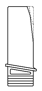
Fig. 6.10. Turbine blade with shears at the end of a trailing edge for
vibrations elimination of vibrations of maximum forms
The second group provides reduction of resonance vibration stresses in blades through lowering exciting forces amplitude values, detuning resonance vibrations, application of constructional damping of the blade vibration, application of compressor stages controls in the following way:
- by increasing axial clearance;
- by improving racks and blades streamlining;
- by using a variable step in a lattice of stator vanes;
- by changing the number, configuration and location of air by-pass windows;
- by phase distributing of exciting forces in a radial direction by application of inclined racks or guide vanes. In this case the vibration stresses in rotor blades can be reduced by 40...50 %, but the amplitudes of the maximum order harmonics are augmented;
- by using antivibrational caps, ring and other shrouds, solid lubricant in the pinned blade (for example, on the basis of bi-sulphide molybdenum – МоS2);
- by using rotor blades elongated shanks;
- by application of doubled rotor blades, i.e. installation of two blades in one groove of the disc, and also using rotor blades hinged attachment with the help of pinned blade. The vibration stresses can be halved in comparison with blades attachment with the help of a “«dovetailed” blade;
- by using compressor control systems of air by-pass or control systems of stator variable vanes.
The third group provides blades strengthening in this way:
- by application of stronger materials;
- by microblobs surface deformation or by method of diamond smoothering, etc.;
- by blade surface grinding and polishing;
- by application of more smoothly varying transitions from airfoil to a blade root and antivibrational caps;
- by perfecting heat treatment technique and deposition of protective coatings.
6.12. Concept of blades self-oscillations
Sometimes, except for forced blades oscillations, there are special self-energizing oscillations, or self-oscillations. They appear when there is no external visible reason for oscillations. The characteristic feature of blades self-oscillations is, first, absence of any pressure or speed pulsation in a flow and, second, connection of self-oscillations origin not with measured engine rotor frequency, but with reduced rotational speed, that is with conditions characterizing flow about blades.
It should be noted, that each self-oscillation has its mechanism. Some of them are studied, many are known in general, and many still remain untreated.
Power concept of self-oscillations consists in the following. In real conditions any oscillations always happen with energy being taken away. The oscillations stability proves that there is an intake of energy to a system. Otherwise oscillations would stop.
The steady-state oscillations can appear without periodic exciting force, but then for them to appear the periodic force effect, which is caused by a source contained in the oscillatory system, is necessary. In Fig. 6.11. the change of damping Edamping and excitation Eexciting energies from amplitude x is shown. The point B determines steady-state oscillations with amplitude xB, at which the excitation energy equals damping energy.
In case of compressor blades self-oscillations there is a mechanism which allows a blade, which began to oscillate because of random deviation, to get energy from an airflow. So oscillation amplitude is set, which can become dangerous. Input and output energies depend on oscillation amplitude. The system kind of controls energies balance through the amplitude.
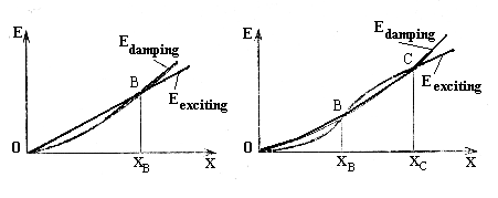
Fig 6.11. Exciting (Eexciting) and damping (Edamping) force energies diagram