

6.2. Kinds and forms of blade normal modes
By nature of deformations, blade normal (free) modes are grouped into:
- flexural oscillations;
- torsional oscillations;
- flexure-torsion (composite) oscillations.
The blade cross sections perform motions without a profile change at these oscillations.
There are also plate-flexural vibration modes with deformation of a profile midline.
At flexural vibrations a blade is considered as a console beam, with infinite number of normal mode forms. Only a few of the lowest forms are of practical interest.
T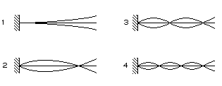 he
normal mode forms are distinguished by number of the
nodes
or nodal lines.
That are blade surfaces, which are not displaced at vibrations. At
the first flexural vibration mode there is only one node at the place
of a blade attachment to the disc (Fig. 6.3, 1).
At the second mode there are two nodes (Fig. 6.3, 2),
etc. (see Fig. 6.3, 3
and Fig. 6.3, 4).
The vibration frequency is the lowest at the first mode. Other
vibration modes have larger frequencies, and, hence, smaller
vibration amplitudes.
he
normal mode forms are distinguished by number of the
nodes
or nodal lines.
That are blade surfaces, which are not displaced at vibrations. At
the first flexural vibration mode there is only one node at the place
of a blade attachment to the disc (Fig. 6.3, 1).
At the second mode there are two nodes (Fig. 6.3, 2),
etc. (see Fig. 6.3, 3
and Fig. 6.3, 4).
The vibration frequency is the lowest at the first mode. Other
vibration modes have larger frequencies, and, hence, smaller
vibration amplitudes.
Fig. 6.3. Flexural vibration modes of rotor blades
Dangerous vibration mode will be the mode, at which the blade normal mode frequency coincides with the vibration excitation forces frequency.
The normal mode frequency can be determined by computation or experimentally.
T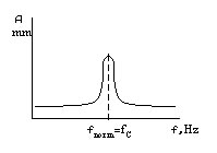 he
simplest and most widespread experimental method is the
resonant method.
In this case the
vibrator
causes vibrations of an examined blade until the resonance. And then
the excitation forces frequency measurement is made. This measured
frequency will correspond to a blade normal mode frequency (Fig.
6.4).
he
simplest and most widespread experimental method is the
resonant method.
In this case the
vibrator
causes vibrations of an examined blade until the resonance. And then
the excitation forces frequency measurement is made. This measured
frequency will correspond to a blade normal mode frequency (Fig.
6.4).
Fig. 6.4. For rotor blade normal mode frequency definition
The vibration modes are more often defined with the help of the sand figures.
6.3. Normal modes of blades with a stationary cross-section area
Let us consider a blade as a weightless console beam with the length L and a constant cross section (Fig. 6.5). Let the weight M be centred on the end of it. And this weight causes the static sag equal to
![]()
where c is a specific flexural stiffness of a blade, N/m (specific flexural stiffness is a force, which causes deformation equal to 1 m).
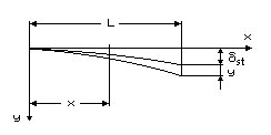
Fig. 6.5. Design scheme for the rotor blade normal mode frequency determination
For the vibrational motion of a blade with some weight an equilibrium equation can be written, applying d'Alembert’s principle
![]()
Let р2 = с/М, and we will get
![]()
where y is a blade deviation from an equilibrium position at vibrations.
The general solution of this equation will be written as
![]()
where A and B are the factors; р is a circular frequency of normal modes; t is time.
Vibration period Т and normal mode frequency fnorm are connected between themselves and a circular frequency by the following ratios:
As р2 = с/М and M = st с/g, we will get
![]()
Hence,
![]()
For the console beam with a stationary cross-section area, with a moment of inertia J, length L and weight M on the end, the static sag makes
![]()
where E is a material modulus of elasticity.
Thus the normal mode frequency will make, [Hz]:
![]()
To derive the formula of normal mode frequency in view of a blade weight it is possible to take advantage of Rayleigh’s method (energy method). In this case we set the form of an elastic line at the first flexural vibration mode, then evaluate the beam sag, kinetic energy and normal mode frequency.
The differential equation of an elastic line of a beam with the weight, which will be close to the form at a static load Q=Mg on the beam end, looks like:
![]()
Its solution for a sag of a beam section, which is in distance x from attachment point of a beam (see Fig. 6.5) is determined by the formula:
![]()
оr
![]()
where
![]() is the maximum sag of a beam.
is the maximum sag of a beam.
The kinetic energy at beam vibrations will equal to:
![]()
where q is weight of a beam length unit; t is time.
Subject to weight on the beam end the formula for kinetic energy looks like:
![]()
If
a period and vibration frequency of a substantial beam with weight
are considered
to be the same, as well as for a weightless beam, which has on its
end weight
![]() ,
the static sag of a beam will be equal to:
,
the static sag of a beam will be equal to:
![]()
and normal mode frequency of a beam without weight (at Q=0) will be equal to:
![]() ,
,
where q=F, F is a sectional area of a beam; is a material density, kg/m3.
Rayleigh showed, that any approximated expression of oscillating beam elastic line form gives the greater frequency value of normal mode, than the precise one.
For the first flexural vibration mode, at which the form of elastic line is close to the form at static load, affecting the end of the beam, the normal mode frequency makes
![]()
where F is a cross-section area of the beam (blade).
As inertia momenta of a blade concerning different axes are various, the oscillations concerning axis of the least rigidity represent greatest interest
From the formula it can be seen, that the normal mode frequency depends on relation Е/, which is determined by a blade material:
- for steel Е/ = 2,82107 Pam3 / kg;
- for aluminium alloys Е/ = 2,52107 Pam3 / kg;
- for titanium alloys Е/ = 2,48107 Pam3 / kg;
- for glass-fibre-reinforced plastics Е/ = 1,32107 Pam3 / kg.
Thus, fnorm of steel blades at the identical geometrical characteristics will be maximum. The blades from aluminium alloys have normal mode frequency that is 6 % smaller than steel blades’, titanium alloy blades frequency is 7 % smaller, glass-fibre-reinforced plastics – 45 % smaller.
At increase blade length the normal mode frequency decreases proportionally to square of relation of blades lengths:

However these ratios are true only for lengthy blades. For short blades with a thick section the idealized formulas give large errors (deviation from experimental data reaches 100 %). It is explained by the fact that the influence of elasticity of a shank in a short blade has a bigger effect, and also that at oscillations the short blade has the form, which is distinct from elastic line of a consol beam. Therefore normal mode frequencies of short blades need to be determined by empirically.
Increase in blade section profile thickness results in increase in its rigidity to a greater degree, compared to increase in its weight. Therefore normal mode frequency will increase with increase in profile thickness. The thinner the blade the more the dispersion of normal mode frequencies is, which is the result of manufacturing inaccuracy and non-uniformity of its wearing in operation.
The blade twist does not affect a blade normal mode frequency much. The vibration frequency under the first form slightly increases at increase of twist (up to 5 % at twist at 45), while the vibration frequency under the second form noticeably decreases (up to 15 % at twist at 45).
The normal mode frequency of a blade is also influenced by the form of transition from a shank to an airfoil part of a blade. It is necessary to note, that at blades oscillations the bending stresses appear not only in airfoil part, but also in a blade shank fixed in the disc. Therefore some correction should be made when calculating a blade normal mode frequency taking into account deformation of a blade shank. In this connection the frequency obtained experimentally, is always less than frequency calculated.
The frequencies of different blade normal mode forms with a stationary cross-section area make the following proportion:
fnorm1: fnorm2: fnorm3: fnorm4: fnormn = 1: 6,28: 17,53: 34,36=1:(k2/k1)2:(k3/k1)2:..:(kn/k1)2,
where k1=1,875; kn=(n–0,5); n=1,2,3,… .
For the blade with a hinged attachment the first flexural vibration mode is missing, therefore comparison begins with the second frequency
fnorm2: fnorm3: fnorm4= 1: 3,24: 6,76=1:(k3/k2)2:(k4/k2)2:..:(kn/k2)2,
where k1=0; kn=(n–0,75); n=2,3… .
For the blades with a variable cross-section area the relation of frequencies have different values, but their frequency always augments with vibration mode serial number increase.
For blades with a shroud ring, stator vanes with two built-in supports or two hinged supports are k1=4,73; kn = (n+0,5) and k1 =; kn=n, respectively.