

Fig. 4.5. Design scheme and character of the radial and circumferential stresses change along radius of two-sided impeller of centrifugal compressor
If the impeller of the compressor has a unilateral input, the bending stress is, as a rule, small and can be ignored, with calculation made by the same algorithms that are used for impeller with two-sided input. It is only necessary to halve the number of blades Z in comparison with the actual number of blades when determining single-sided impeller reduced density.
In existing designs of centrifugal compressors the maximum stresses in rotor wheel discs made of aluminium-based alloys reach 250...280 MPa.
4.8. Peculiarities of stresses calculation in drum-and-disc designs
In considered designs the stresses are determined both in discs, and in rotor drum-type parts.
It is possible to consider the most favourable arrangement of drum-type parts (in the sense of tensile strength), when they do not loads the discs, i. е. when they are cantilever elements of a rotor. To meet this requirement it is necessary to select the radius of drum wall arrangement rdrum (Fig. 4.6) so that the radial movements of the disc and drum part in a place of its fixing (at the radius rdrum) are identical ( d = drum).
Movements (deformations) d and drum are determined by equations of deformation generality and physical equations, considered in item 4.5.2:
 (4.13)
If
there are analytical relations of stresses in the disc
![]() and in the drum wall
and in the drum wall
![]() versus the radius of fixing rdrum,
then, equating right members of ratio (4.13), it is possible to
determine the value rdrum,
ensuring the
radial disconnectedness of
the disc and drum part. However, as was noted above, the analytical
solutions of stressed state equations can be obtained only for the
elementary disc shapes. Let us consider stresses
versus the radius of fixing rdrum,
then, equating right members of ratio (4.13), it is possible to
determine the value rdrum,
ensuring the
radial disconnectedness of
the disc and drum part. However, as was noted above, the analytical
solutions of stressed state equations can be obtained only for the
elementary disc shapes. Let us consider stresses
![]() and
and
![]() as
values, given by disc shape beforehand, and a stress in a free drum
part will be determined being considered as a
thin-walled barrel
(see Fig. 4.6).
as
values, given by disc shape beforehand, and a stress in a free drum
part will be determined being considered as a
thin-walled barrel
(see Fig. 4.6).
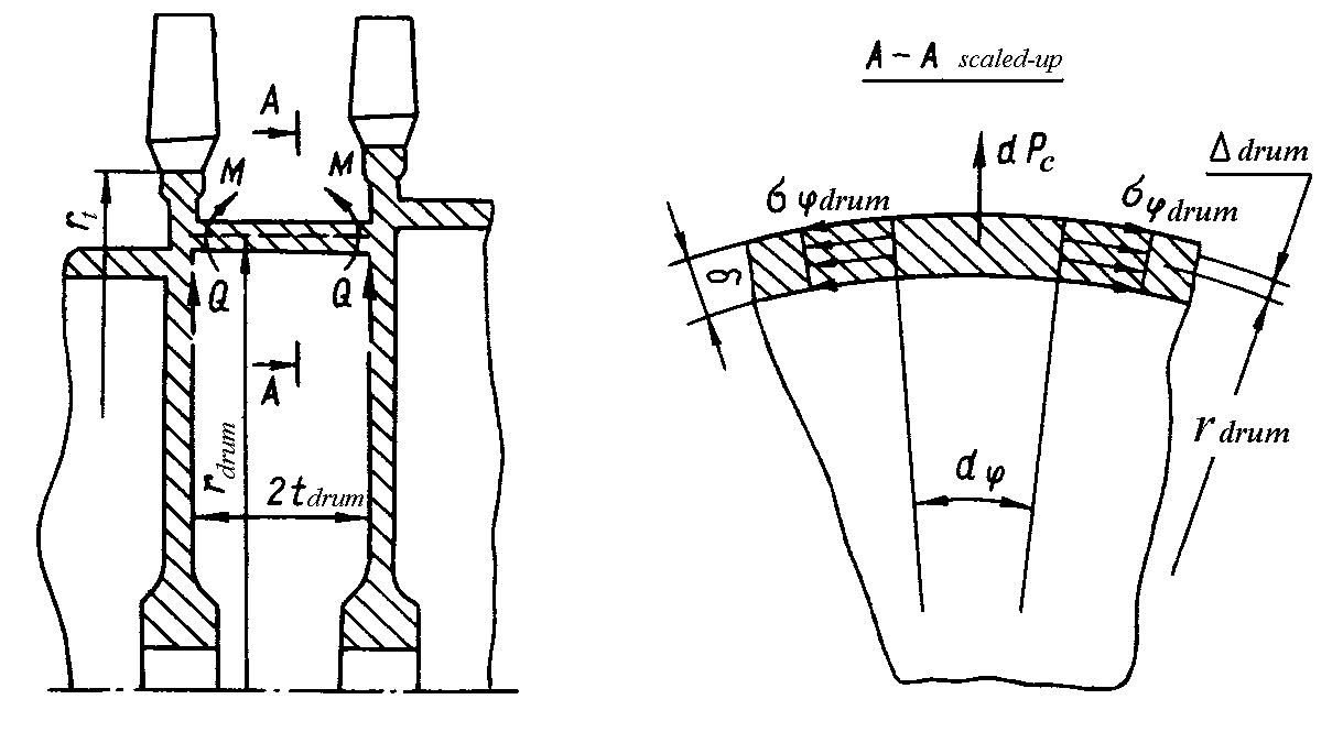
Fig. 4.6. Design scheme of a drum-and-disc rotor
Assuming that the circumferential stresses are constants along drum wall thickness (in view of its smallness) and neglecting value of radial stresses (r drum=0 ), we will make the following equilibrium equation of drum element:
![]() (4.14)
(4.14)
From here
![]() (4.15)
(4.15)
where ldrum=2tdrum (see Fig. 4.6).
According to an adopted requirement d = drum and from ratios (4.13), (4.15) at r drum=0, Td=Tdrum we will get
![]() .
(4.16)
.
(4.16)
The values rdrum, d and r d are interdependent. Therefore, equation (4.16) needs to be solved by successive approximations, setting a series of values rdrum and defining from the charts of stress distribution along disc radius the corresponding values d and r d. For constant width discs without blades the radius of a cantilever drum wall makes r0,5rt . About the same ratio is characteristic for real (harder) discs with blades.
In existing designs of drum-and-disc rotors to increase their flexural stiffness the drum parts are placed on radiuses, close to an outer radius of discs rt (radius of disc rim part). Thus, the requirement of a radial disconnectedness (4.16) is defaulted and drum parts additionally load the discs by centrifugal forces. At this they are loaded by bending momenta M and shearing forces Q in places of their fixing (see Fig. 4.6).
At detailed calculation of stresses in places of drum wall fixing the values of bending momenta M and transversal forces Q are determined by methods of thin shells theory. In executed designs of rotors the circumferential stresses in places of drum part fixing subject to their bending make (0,5...0,8) drum, where drum is stress determined by the formula (4.15).