

3.6. Evaluation of gte rotor blades strength
3.6.1. Grounding of blade stressed state criterion
The stresses caused by mechanical forces affect the rotor blades in one plane. The stressed state criterion for them will be the algebraic total of all stresses
![]()
where Т is thermal stresses stipulated by a non-uniform temperature distribution in the blade section (the thermal stresses calculation is not considered here).
Thus, the total stresses must be recalculated in elasto-plastic deformation area if they fall outside the proportionality limits in any blade section points. We do that with the help of variable elasticity parameters method.
By their action character the total stresses can be tensile stresses or compressive stresses in manifold section points. The tensile stresses usually act in the most loaded section points at the design ratings. Therefore, as limiting (destroying) stress for turbine rotor blades, the long-term strength Т of material is used. They correspond to the given temperature T of a section point and to the time before destruction. The material destruction at the long-term static loading occurs owing to creep strain accumulation under the affect of Т stress at T temperature.
The gas turbine rotor blades intensively exhaust the long-term strength owing to high temperature effect.
3.6.2. Estimation of the blade temperature
To protect a rotor and turbine casing details from excessive thermal influence, the gas flow temperature in blade tip and root sections is reduced with the help of the secondary air application. The gas local temperature Т*g (Fig. 3.9, a) reaches its maximum values in the central part of the gas-flow channel and, as a rule, it exceeds “mean-weight” temperature.
The blades will be subject to maximum heating in the central zone as well due to such gas flow temperature diagram. Nevertheless, the temperature in the blade root Tb r is much lower than the mean temperature Tmean (difference between them Тr = Tb r‑Tmean makes 100...200 С) owing to heat rejection from blade profile part to the disc rim, which are, as a rule, intensively cooled by air. In this case the temperature of the blade in the i‑th section distributed along its length (hi) is determined by the equation
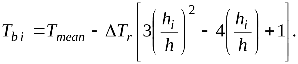
According to it the temperature maximum is at 2/3 of the blade length from the root, and the temperature is equal to Tmean in the tip section (hi = h) and at hi=h/3. Such temperature distribution along the blade length agrees with actual data for most GTEs.
F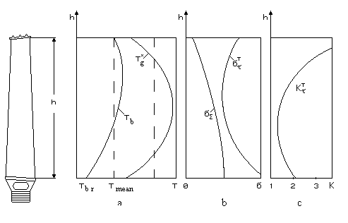 ig.3.9.
Turbine rotor blade temperature (a),
stress (b)
ig.3.9.
Turbine rotor blade temperature (a),
stress (b)
and long-term safety factor coefficient (c) change along the blade length
The turbine rotor blades mean temperature is determined by the formula
![]()
where T*g is a “mean-weight” gas temperature before the turbine stage; Lst is a specific gas expansion work in the stage; Umean is a rotor wheel circumferential velocity at a mean radius; Kcool=0,8...0,9 is a factor, taking into account the difference between air temperatures behind the compressor T*c and in the place where it is bleeded for blades cooling; cp g is a thermal gas capacity; is a factor, taking into account the depth of cooling (specific depth of cooling)
![]()
In
this equation
![]() is
a
total gas temperature before rotor blade
at
relative motion (
is
a
total gas temperature before rotor blade
at
relative motion ( ,
where subscript “1” correspond
to
rotor wheel inlet);
,
where subscript “1” correspond
to
rotor wheel inlet);
![]() is a cooling air temperature.
is a cooling air temperature.
We take = 0 for the uncooled turbine blades, which are used at rather low gas temperatures before the stage (at T*g = 1150...1250 K). And we take = 0,2...0,25 for the blades, which have radial channels (at T*g = 1350...1450 K) and internal convective cooling. We take = 0,3...0,4 for the blades with deflectors of convective cooling (at T*g = 1400...1500 K). It is possible to take = 0,4...0,45 and higher at convective-film first stage blades cooling. Such blades provide gas temperature of 1600...1650 K.