

3.3.4. Determination of the blade section geometrical characteristics
It is necessary to define center of gravity position of a section area and major axes of inertia for calculation of a bending stress in blade design section. The center of gravity position is easy to define by two-three arbitrary suspensions of section profile model, which is cut out from a dense paper or cardboard (Fig. 3.3). The crosspoint of verticals 4, drawn in a suspended state through the point of suspension 5, along a thread 2, stretched with some weight 1, gives center of gravity position 3. The center of gravity of the strongly curved turbine blade airfoil section can be outside of a profile contour. Besides, the center of gravity coordinates can be calculated using Simpson’s method.
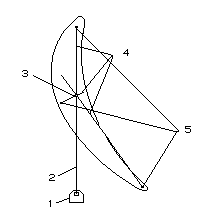
Fig. 3.3. Scheme of a blade section center of gravity definition
W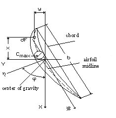 ith
no big error being made, it is possible to accept, that the
main axis of inertia
,
passing through section
center of gravity
C,
is parallel to profile
chord.
Axis
is perpendicular to axis .
Thus main central axes of inertia are turned at angle
about central axes xCy
(Fig. 3.4).
ith
no big error being made, it is possible to accept, that the
main axis of inertia
,
passing through section
center of gravity
C,
is parallel to profile
chord.
Axis
is perpendicular to axis .
Thus main central axes of inertia are turned at angle
about central axes xCy
(Fig. 3.4).
Fig. 3.4. Scheme of the blade section geometrical characteristics definition
With no big error being made, the inertia momenta of section profile about axes and can be determined through the profile parameters by the formulas:
for turbine blades:
![]()
for compressor blades:
![]()
where b is a chord of the profile; Cmax is the maximum profile thickness; f is the maximum sag of a profile midline, which is the maximum distance from the profile midline to a chord (it is not shown in Fig. 3.4).
The profile section area can be determined by planimetry or approximately calculated by the formula
![]()
Determination of bending stress caused by gas force
The equations of a stressed state at a skew bending are made in case, when the bending moment comes into action in a plane perpendicular to neutral section line. That’s why the bending momenta Mg y and Mg x must be projected to the main central inertia axes of blade section, which will be neutral section lines.
We will apply the same rule of signs for the momenta vectors projections on the axes and , as for force vector. We will consider momenta vectors projections positive, if they coincide with axes direction.
The components of the resultant vector of the bending moment about main central inertia axes of blade section can be determined from such ratio (Fig. 3.5):
- for the turbine blades
![]() ;
;
![]() ; (3.23)
; (3.23)
- for the compressor blades
![]() );
);
![]() ).
(3.24)
).
(3.24)
Formulas (3.23) and (3.24) yield the equation
![]()
which shows, that the modules of bending moment resultant vector are equal in both coordinate systems.
The bending stress in an arbitrary point of the blade section with coordinates i and i is determined by the formula
![]() (3.25)
(3.25)
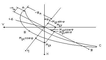
Fig. 3.5. Scheme of the bending momenta vectors projection to
the main central inertia axes of a turbine blade section
Values of the momenta Mg , Mg and coordinates i, i should be used with signs in the formula (3.25).
The second addend in formula (3.25) is preceded by “minus” to meet the commonly accepted rule of stress signs, according to which the tensile stress goes with “plus” while the compressive stress has “minus”.
We will get an equation of a blade section neutral line making bending stress equal to zero, which is determined by the formula (3.25)
![]() (3.26)
(3.26)
It is the equation of a straight line with pitch to an axis determined from the ratio
![]()
The value of inertia moment J considerably exceeds the one of J (the momenta of inertia ratio J/J makes 0,01...0,05 for the compressor blade profiles, and for the turbine blade profiles it makes 0,05...0,15). The bending momenta M and M are, as a rule, values of one order. Therefore, angle is of a small value and axis can be taken as a neutral section line, which is parallel to a blade chord.
The greatest stresses appear in points A, B, C most remote from a neutral section line (see Fig. 3.5), which we usually take as design points. The tensile stresses appear in points A and C, and squeezing stress appears in point B.
The maximum bending stresses, caused by the gas forces reach 50...120 MPa in the compressor blades at first stages and 150...250 MPa at last stages. The maximum stresses reach 30...150 MPa in the turbine blades.