
- •Foreword
- •Предисловие
- •Chapter 1. Introduction
- •From the history of aeroengines development. Classification of air gas turbine engines
- •Table 1.1
- •Table 1.2
- •1.2. Design features of manifold types of gas turbine engines
- •Main specifications for some serial turboprop and turboshaft
- •Fig. 1.3. Principal scheme of a two-shaft afterburning
- •Fig. 1.4. Principal scheme of a two-shaft tfe
- •Fig. 1.5. Principal scheme of a three-shaft tfe
- •Fig. 1.8. Principal scheme of a tpfe with a coaxial propfan
- •Main stages of gas turbine engines creation
- •1.4. Absolute and specific parameters of gas turbine engines
- •1.4.1. Absolute and specific parameters of turbojet engines
- •1.4.2. Absolute and specific parameters of turboprop engines
- •I.5. Air gas turbine engine’s lives
- •1.5.1. Nomenclature of lives
- •1.5.2. Sequence of assigning, setting and increase of lives
- •1.5.3. General requirements to life testing of engines and their main elements
- •1.5.4. Forming of test cycles
- •1.5.5. Forming of programs of life tests
- •Questions for self-check
- •2.1. Types of loads acting upon gas turbine engine structural elements
- •2.1.1. Classification of loads
- •2.1.2. Gas loads
- •2.1.3. Mass (inertial) forces and momenta
- •2.1.4. Temperature stresses
- •Fig. 2.4. For determination of the centrifugal forces
- •Fig. 2.5. For determination of the disc temperature stresses
- •2.1.5. Concept of dynamic loads
- •Fig. 2.9. Gas flow velocity behind nozzle vanes
- •2.2. Axial gas forces coming into action in gas turbine engines. Formation of thrust in gas turbine engines of manifold types
- •2.2.1. Axial gas forces acting on the basic gas turbine engine units
- •Fig. 2.10. Scheme of axial forces acting on basic gte units
- •2.3. Determination of axial gas force acting on impeller of gas turbine engine centrifugal compressor
- •2.4. Torques coming into action in gas turbine engines. Balance of torques
- •In gas turbine engines
- •2.4.1. Torques in turbine and compressor
- •Fig. 2.14. For determination of turbine rotor wheel torque
- •2.4.2. Torque balance in gas turbine engines of manifold types
- •Questions for self-check
- •Engine blades
- •Loads acting on blades. The blade stressed state characteristic
- •Fig. 3.1. Loads acting on the blade (a) and the scheme of blade loading
- •Determination of rotor blade tensile stress caused by centrifugal forces
- •The design scheme
- •3.2.2. Equation of a rotor blade stressed state
- •Integrating equation (3.3) in view of the ratio (3.1), we will get
- •3.2.3. Calculation of tensile stress at manifold laws of change of blade section area along its length
- •If the blade section area decreases from the root to periphery under the linear law:
- •In this case an integration by formula (3.7) yields
- •Determination of rotor blade bending stress caused by gas forces
- •3.3.1. Design scheme of a blade
- •3.3.2. Determination of gas load intensities
- •Determination of the bending momenta in axial and circumferential planes
- •3.3.4. Determination of the blade section geometrical characteristics
- •Determination of bending stress caused by gas force
- •Determination of rotor blade bending stress caused by centrifugal forces
- •The design scheme
- •3.4.2. Equation of the bending momenta
- •3.5. Guide and nozzle diaphragm vanes strength calculation features
- •3.5.1. Console type vanes
- •3.5.2. Double-support vanes
- •3.5.3. Frame type vanes
- •3.6. Evaluation of gte rotor blades strength
- •3.6.1. Grounding of blade stressed state criterion
- •3.6.2. Estimation of the blade temperature
- •3.6.3. Determination of blade strength safety factor coefficients
- •Questions for self-check
- •4.1. Loads affecting discs
- •The design scheme and assumptions made at disc strength calculations
- •Fig.4.1. Design scheme of the disc
- •4.3. Design ratings
- •4.4. Disc thermal condition
- •4.5. The disc stressed state equation. Boundary conditions
- •4.5.1. An equilibrium equation
- •4.5.2. Equation of deformations generality
- •4.5.3. Determination of stresses in rotating, unevenly heated elastic disc with an arbitrary profile
- •Fig. 4.2. Elementary disc forms
- •Fig. 4.3. Discs of arbitrary profiles
- •4.5.4. The procedure of the arbitrary profile disc stresses calculation
- •4.6. Disc durability criteria and safety factor coefficients
- •4.6.1. Selection of the stressed state criteria
- •4.6.2. Disc safety factor coefficients
- •Integrating an equilibrium equation, we find
- •4.7. Features of strength calculation of centrifugal compressor and radial-inflow turbine discs
- •The weight of the carrier disc for a chosen ring makes
- •Fig. 4.5. Design scheme and character of the radial and circumferential stresses change along radius of two-sided impeller of centrifugal compressor
- •4.8. Peculiarities of stresses calculation in drum-and-disc designs
- •Fig. 4.6. Design scheme of a drum-and-disc rotor
- •From here
- •Questions for self-check
- •Chapter 5. Static strength of gas turbine engine shafts
- •Loads acting on shafts
- •Design schemes and stressed state of shafts. Safety factor coefficient estimation
- •In an axial direction the shaft tensile (compressive) stresses are equal to
- •The shaft static strength is estimated by a safety factor coefficient value
- •Questions for self-check
- •Chapter 6. Dynamic strength of gas turbine engine blades
- •6.1. Vibrations of blades and forces causing vibrations
- •6.2. Kinds and forms of blade normal modes
- •Fig. 6.3. Flexural vibration modes of rotor blades
- •Fig. 6.4. For rotor blade normal mode frequency definition
- •6.3. Normal modes of blades with a stationary cross-section area
- •6.4. Normal modes of blades with a variable cross-section area
- •6.5. Influence of blade attachment effort to the disc
- •6.6. Influence of centrifugal forces on blade vibration frequency
- •F ig. 6.7. Determination of blade dynamic normal mode frequency
- •Influence of variable temperature
- •6.8. Forces damping blade vibrations
- •6.9. Resonant modes of the blade vibrations. The frequency diagram
- •F ig. 6.8. Example of turbine rotor wheel frequency diagram
- •6.10. Torsional and composite blade vibrations
- •6.11. Elimination of blade vibrational breakages
- •6.12. Concept of blades self-oscillations
- •Versus vibration amplitude
- •Questions for self-check
- •Chapter 7. Dynamic strength of gas turbine engine discs
- •General information
- •Forms of disc normal modes
- •Wave linear speed equals
- •Disc normal mode frequency
- •The compressor and turbine rotor wheel vibration calculation
- •Factors influencing the disc normal mode frequency
- •Disc forced undulations
- •The ways to eliminate dangerous resonance oscillations of rotor wheels
- •Questions for self-check
- •Chapter 8. Critical rotational speeds of gas turbine engine rotor
- •8.8. Measures taken to reduce intensity of rotor oscillation connected with critical rotational speeds.
- •Concept of critical rotational speeds of gas turbine engine rotor
- •Critical rotational speed of the two-support weightless shaft with disc
- •Fig. 8.8. Value of shaft static sag for different rotor schemes
- •Fig. 8.9. To the problem of a rotated rotor stability in a subcritical area
- •Connection of rotor critical rotational speed with its
- •Concept of two-support rotor critical rotational speeds of higher order
- •Critical rotational speed of the two-support ponderable shaft without disc
- •8.6. Critical rotational speeds of the ponderable shaft with several discs
- •8.6.1. Method of decomposition into elementary systems
- •8.7. Operational factors affecting critical rotational speeds of gas turbine engine rotor
- •Fig. 8.11. Taking into account supports elasticity influence on rotor critical speeds
- •Fig. 8.12. Static elastic anisotropy of a casing
- •Determination of critical rotational speeds taking into account
- •Influence of gyroscopic moment
- •Table 8.1
- •Values of the influence coefficients
- •8.7.2. Reduction of a real flexural system to equivalent computational
- •Example of rotor critical speed calculation
- •The rotor operational rotational speed margin is equal to:
- •The rotational speed margin at an idle is equal to:
- •8.8. Measures taken to reduce intensity of rotor oscillation connected with critical rotational speeds
- •Questions for self-check
- •8.7. What is dependence of rotor critical rotational speed on its cross-sectional oscillation frequency?
- •Of gas turbine engine shell designs
- •9.1. Shell strength calculation
- •Fig .9.1. Design scheme of a shell
- •9.2. Stability of cylindrical and conical shells
- •9.3. Vibrations of cylindrical shells
- •Questions for self-check
- •Chapter 10. Control of gas turbine engine
- •Vibration state
- •10.2. Control of gas turbine engine vibrations
- •10.3. The ways to lower the vibration level of gas turbine engines
- •10.3.1. The procedures of vibration level lowering at stage of designing
- •10.3.2. The procedures of the vibration level lowering at production stage
- •Fig. 10.3. Scheme of the rotor static balancing
- •Fig. 10.4. Scheme of the rotor dynamic balancing
- •Will be compensated by centrifugal force of balanced elements weights
- •10.3.3. The procedures of the vibration level lowering at maintenance stage
- •Questions for self-check
- •Сhapter 11. Gas turbine engine rotor supports
- •11.1. Brief data about gas turbine engine rotor supports
- •Fig. 11.3. Scheme of gte rotor support
- •11.2. Calculation of support bearings
- •Fig. 11.9. Ball bearing:
- •For roller bearings we use the formula
- •11.2.2. Estimation of the bearing safe life
- •11.2.3. Check of the bearing high-speed
- •11.2.4. Check of the bearing static load-bearing capacity
- •11.2.5. Definition of the necessary oil circulation through the bearing
- •Questions for self-check
If the blade section area decreases from the root to periphery under the linear law:
(3.10)
than integration by formula (3.7) will result in:
(3.11)
where h=R0-Rr is the length of blade airfoil part.
The maximum stress takes place in the blade root and is calculated by the formula
(3.12)
We can see from the formula (3.12), that the considerable stress reduction can be reached if area ratio F0/Fr is decreased. In modern compressor rotor blades F0/Fr=0,25...0,35, which permits along with other equal terms to reduce stress in blade root by 30...35 % compared with stresses in the constant area blades.
The blade section area changes according to the exponential law
(3.13)
where q is an exponent (q=0,5...0,6 for turbine blades; q=1 for compressor blades).
In this case an integration by formula (3.7) yields
(3.14)
For the blade root from the formula (3.14) we will have
(3.15)
As it follows from the formula (3.15), the exponent q decreasing from 1 to 0 results in a considerable stress reduction in the blade root as compared with the law of linear areas changing. In this case the maximum of stress moves from blade root to mean section that may result in underloading of turbine rotor blades root. Therefore, it is necessary to optimize selection of an exponent q. At optimal values of q and F0/Fr the tensile stress in the blade root can be reduced by 40...45 % in comparison with version F=const.
If the blade section area changes according to arbitrary law, then the approximate integration by formula (3.7) should be done to define stresses, for example, by Simpson’s rule. In this case we will get the following recurrence formula:
(3.16)
where i=2,4,6... are even numbers of design sections; n is the number of all sections, which should be even.
The maximum values of tensile stresses by centrifugal forces in axial compressors reach 300...350 MPa for steel blades, 100...150 MPa for blades from aluminium‑based alloys and 200...250 MPa for blades from titanium‑based alloys. The maximum tensile stresses can reach the values of 250...300 MPa in gas-turbine rotor blades, though in actual designs they seldom exceed 200 MPa.
Determination of rotor blade bending stress caused by gas forces
The geometry of rotor blades airfoils or blade attachment to the disc are designed so that the bending momenta, caused by gas and centrifugal forces, have opposite directions. Therefore the full or partial blade bending stress unloading will be provided. It is necessary to analyze the blade bending stress, caused by gas and centrifugal forces separately, to perform in the right way.
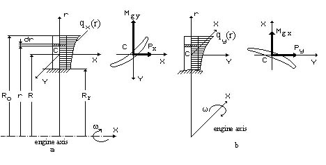
Fig. 3.2. Design scheme of turbine rotor blade loading with gas forces
in axial (a) and circumferential (b) planes
3.3.1. Design scheme of a blade
The gas force is distributed along an airfoil center-of-pressure line and affects the blade. It is characterized by load intensity in an axial plane qx and in a plane of rotation qy (Fig. 3.2). Load intensity is the force which acts on the blade length unit. Generally gas load intensity is distributed along radius according to the arbitrary law. Nevertheless it can be accepted as a constant value along the blade airfoil part when roughly calculated.
Let us consider a blade as an asymmetrical section rod with arbitrary variation of a section area along its length. A blade is considered rigidly nipped in the disc with the blade bending about this disc.
In arbitrary section of a blade at the radius r (see Fig. 3.2) we will place local (rotating) coordinate system xCy. We will arrange origin C in the center of gravity of the section under consideration (x axis is directed towards the gas flow movement, and y axis – along the tangent to a circle of R radius towards the rotor rotation). We will consider the intensities of gas loads positive, if their vectors coincide with directions of x and y axes.
Vectors of the bending momenta, coming into action in an axial plane (Mg y) and a plane of rotation (Mg x), will be guided along x and y axes, always in positive direction.
According to the design scheme considered, the problem of blade bending calculation is reduced to the problem of asymmetrical section beam skew bending.