

2.4. Torques coming into action in gas turbine engines. Balance of torques
In gas turbine engines
2.4.1. Torques in turbine and compressor
The torques in the turbine and compressor rotor wheels come into action owing to summation of circumferential components of gas forces, which act on the rotor blades (Fig. 2.14). The turbine rotor wheel torque has a positive sign, because it performs a useful work of engine rotor rotation. The compressor rotor wheel torque has a negative sign, because this is resistance torque.
The circumferential force acting on the turbine rotor wheel is equal to:
![]() .
.
Turbine rotor wheel torque is calculated from the equation
![]()
The multistage turbine rotor torque is equal to:
![]()
where ZT is the number of turbine stages.
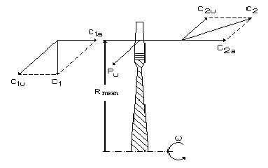
Fig. 2.14. For determination of turbine rotor wheel torque
Torque, acting on the turbine rotor, can be calculated if the turbine power Nt and angular speed of rotor rotation are known:

where Lt is a specific expansion work of gas in the turbine, J/kg.
The compressor rotor torque is determined in a similar way. All components will have signs opposite to turbine torque’s.
2.4.2. Torque balance in gas turbine engines of manifold types
The TJE turbine rotor is loaded with torque, which is transmitted to compressor rotor and accessory drive:
![]()
where Mdr=(0,01...0,06)Mc.r is a torque, transmitted from turbine to accessory drives.
Hence, we can consider
![]()
As air and gas flow inlets and dischardges in compressor and turbine units have an axial direction, the compressor and turbine stators torques are equal to the torques on their rotors, but are of opposite signs:
![]()
![]()
For engine stator we get
![]()
This equality is true if the torque is transmitted from engine casing to attachment fittings only in one plane, and in the other plane attachment fittings will not transmit the torque.
Questions for self-check
1. Analyze loads acting on the GTE structural elements.
2. Analyze formation of axial, circumferential and radial gas forces.
3. Explain the nature and calculation techniques of mass (inertial) loads and momenta.
4. What causes dynamic loads acting on the engine details?
5. How are the gas loads calculated?
6. How are the gas loads acting on the GTE basic units calculated?
Explain the origin of a torques taking place in engine rotors and stators.
Chapter 3. STATIC STRENGTH OF GAS TURBINE
Engine blades
Loads acting on blades. The blade stressed state characteristic.
3.2. Determination of rotor blade tensile stress caused by centrifugal forces.
3.3. Determination of rotor blade bending stress caused by gas forces.
3.4. Determination of rotor blade bending stress caused by centrifugal forces.
3.5. Features of the guide and nozzle vanes strength calculation.
3.6. Evaluation of gas turbine engine rotor blades strength.
Literature: [1], p. 221–257; [2], p. 235–247; [3], p. 168–200; [4], p. 111–122; [5], p. 45–84.
Loads acting on blades. The blade stressed state characteristic
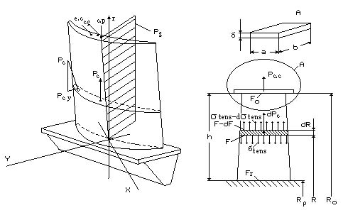
The most loaded GTP details are the compressor rotor blades and the turbine rotor blades. The centrifugal and gas forces affect them.
The centrifugal forces cause tensile, bending and torsion of the blades. The greatest value is reached by tensile stresses. The bending by the centrifugal forces Pc (Fig. 3.1, a) arises because in most cases gravity centers line of blade sections (g.c.) does not coincide with a radial axis r, which passes through gravity center of blade root. The blade torsion is connected with the cross-sectional components of centrifugal forces Pc y. They create a torque about elastic center (e.c.). It is directed to the plane of rotation.
The gas forces are distributed over the blade surface. Their resultant Pg is affixed to a center-of-pressure line (c.p.). They cause the blade bending and torsion, because the center-of-pressure line, as a rule, does not coincide with the line of elastic centers.
The rotor blades torsional stresses, which are caused by centrifugal and gas forces are usually not large and we neglect them in preliminary calculations. The exception is made for thin, strongly twisted blades, ends of which can lose stability because of torque.
The stator vanes (guide vanes, directing vanes and nozzle diaphragms) are subject to the effect of gas forces. They cause blade bending and small torsional stresses.
In addition to power effects the rotating and fixed blades of turbines and compressor final stages are irregularly heated in a volume. It causes appearance of considerable blade temperature stresses. The irregular heating creates volumetric thermostressed state in the blades. However, in comparison with thermal stresses, acting along blade axis, other tensor components of thermal stresses are small (at comparatively small temperature gradients). As calculations demonstrate, they can be neglected.
 a b
a b