

2.1.4. Temperature stresses
The temperature stresses appear because of limitation of a temperature movement of the engine structural elements or their separate parts. The limitations of temperature movements take place in two situations:
- when a detail is heated or cooled irregularly;
- when external power connections are superposed on a heated structural element.
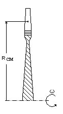
Fig. 2.4. For determination of the centrifugal forces
D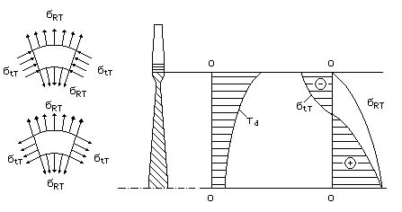 uring
irregular
heating
of details (Fig. 2.5, Fig. 2.6) their more heated parts
tend to extend more than their less heated parts, and cause a tensile
of less heated parts. The
less heated parts of a detail limit a more heated parts extension,
which results in compressive
temperature stresses
in more heated parts.
uring
irregular
heating
of details (Fig. 2.5, Fig. 2.6) their more heated parts
tend to extend more than their less heated parts, and cause a tensile
of less heated parts. The
less heated parts of a detail limit a more heated parts extension,
which results in compressive
temperature stresses
in more heated parts.
Fig. 2.5. For determination of the disc temperature stresses
The temperature stresses will take place even at uniform heating owing to a superposition of external connections on the heated engine structural element (Fig. 2.7).
In case of uniform heating of a rigidly fixed rod with length L (see Fig.2.7), a relative compressive strain takes place in it, which is equal to:
![]()
which is determined as
![]()
w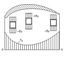 here
T
is a
coefficient of a linear extension
depending on temperature, K–1
(Fig. 2.8); T is
a
temperature increment at heating,
K.
here
T
is a
coefficient of a linear extension
depending on temperature, K–1
(Fig. 2.8); T is
a
temperature increment at heating,
K.
Fig. 2.6. For determination of the blade temperature stresses
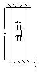
Fig. 2.7. For determination of a compressive strain
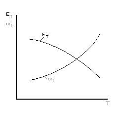
Fig. 2.8. T and ET dependence of temperature
The temperature compressive stresses for the case under consideration can be determined as
![]()
where ET is an elasticity modulus of a rod material, Pa, depending on temperature (see Fig. 2.8).
We try to eliminate the temperature stresses, resulting from superposition of external power connections. The hinged mobile connections of heated details with less heated ones are applied. The details are specially cooled by air to avoid large temperature movements and stresses if it is impossible.
2.1.5. Concept of dynamic loads
The dynamic load frequencies vary from hundreds of Hz up to hundreds of kHz. Such loads are called vibrational.
They are caused by a rotor’s dynamic unbalanced state, that causes inertial forces of its unbalanced masses:
![]()
where res is a residual rotor’s unbalance, res= (5...50)10-5 kgm; is an angular velocity of rotor rotation, s–1.
B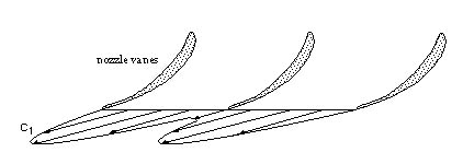 esides,
there are some more reasons for a dynamic load. The most important
reason is a non-uniformity of gas flow parameters in engine air-gas
channel, for example, gas flow velocity or pressure (Fig.
2.9).
esides,
there are some more reasons for a dynamic load. The most important
reason is a non-uniformity of gas flow parameters in engine air-gas
channel, for example, gas flow velocity or pressure (Fig.
2.9).
Fig. 2.9. Gas flow velocity behind nozzle vanes
The highest levels of vibrational stresses take place under resonance of low frequency oscillations, close to rotor rotation frequency. These resonant ratings should be eliminated from engine ratings, or we should reduce detail oscillation amplitudes with the help of damping.
2.2. Axial gas forces coming into action in gas turbine engines. Formation of thrust in gas turbine engines of manifold types
2.2.1. Axial gas forces acting on the basic gas turbine engine units
The axial force acts on each engine unit (Fig. 2.10). This force is the sum of an active and jet components. The direction of axial force is positive, if it coincides with a thrust vector direction.
The axial force acting on the inlet is equal to:
![]()
![]() ,
,
where Ga is a mass air flow rate, kg/s. An external diameter of compressor air-gas channel in some section is lettered D, and internal diameter is lettered d.
An inlet axial force makes 30...40 % of engine take-off thrust R:
![]()
The axial force acting on the compressor air-gas channel is equal to:
![]()
Put in a different way it looks like
![]()
where c = pcd / pci.
The axial force acting on the compressor rotor wheel air-gas channel can be precisely determined by summation of axial forces acting on all compressor rotor wheels. Approximately it can be determined with the help of the compressor reactivity mean degree c (for gas-static component) if the gas-dynamic component is evenly distributed between the rotor and stator:
![]()
w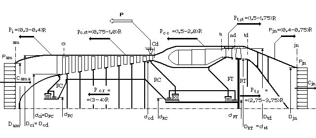 here
c=
0,7...0,75.
here
c=
0,7...0,75.