

2.1.2. Gas loads
Gas loads are connected with operation of GTE as a heat machine. They result from the affect of a gas flow on all engine devices. The force formation in the GTE air-gas channel is of a particular interest.
Gas loads can be axial, circumferential, and radial, depending on their direction.
The axial gas force acting on the engine air-gas channel element (Fig. 2.1) is equal to:
PAX=PGS+PGD ,
where PGS is a gas-static (active) component, N; PGD is a gas-dynamic (jet) component, N.
The force PGS is determined by the difference of the static loads:
![]() ,
,
where p1, p2 are the channel inlet and outlet gas pressures, respectively, Pa; F1, F2 are the cross-sectional areas of the channel inlet and outlet, respectively, m2; D, d are the diameters, m (see Fig. 2.1).
The force PGD is determined by momentum change of a gas flow in an air-gas channel:
![]() ,
,
where Gg is a mass gas flow rate, kg/s; c1a, c2a are the axial components values of a gas absolute speeds in the channel inlet and outlet, respectively, m/s.
The total axial force acting on the air-gas channel element (see Fig. 2.1) is equal to:
![]()

Fig. 2.1. Design scheme for determination of gas forces acting on the engine air-gas channel element
The circumferential gas forces are determined by momentum change of a gas flow in a circumferential direction, i.e. the circumferential gas forces are gas-dynamic forces:
![]()
where c1u, c2u are the circumferential component values of the gas absolute speeds in the channel inlet and outlet, respectively, m/s (see Fig. 2.1).
The radial gas forces appear from the difference between gas static pressures in air-gas channel and in external (subscript ex) or internal (subscript in) cavities of the engine.
The resultant radial force that acts on a ring casing (Fig. 2.2) is equal to:
![]() ,
,
where L is an axial length of a channel, m.
The radial gas forces are internal forces. They are balanced in the engine structural elements and cause tensile or compression, and in some cases bending of the casings. The most dangerous case is a compression of a thin-walled casing that may cause a rigidity loss. The rigidity of such casings must be calculated and necessary sufficient rigidity reserve is provided.
Unlike the radial forces, the axial and circumferential gas forces can be both internal and free.
F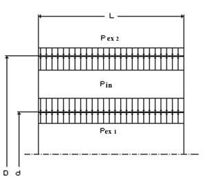 ig.
2.2. Resultant radial force that acts on a ring
casing
ig.
2.2. Resultant radial force that acts on a ring
casing
2.1.3. Mass (inertial) forces and momenta
The mass (inertial) forces are caused by any acceleration. So, an engine weight is determined by the formula
![]() ,
,
where Meng is a mass of engine, kg; g is a gravitational acceleration, m/s2.
The centrifugal forces act on the rotor structural elements during engine rotor rotation. They are caused by a centrifugal acceleration, which is not equal to zero even during uniform rotation.
The centrifugal forces PC are internal (made) in an ideally balanced rotor. They make the rotor elements tension and are not transmitted to the casing.
For example, PC of a blade is equal to:
![]()
where mb is a blade mass, kg; is an angular velocity of rotor rotation, s–1; RCM is a radius of the blade mass center, m (Fig. 2.4).