

4.2 Gas pipeline hydraulics principles
The factors that influence the characteristics of gas flow in transmission lines, though numerous and complexly related, are as follows:
physical properties of the gas
density of the gas
viscosity of the gas
molecular weight of the gas
thermal conductivity of the gas
heat capacity of the gas
temperature and pressure base
conduit properties and soil properties
internal pipe diameter
length of segment in question
pipe wall roughness
burial depth to centre line of the pipe
soil temperature and conductivity
properties of the operating pipeline
The operating characteristics are determined by a combination of the following:
the amount of flow (mass flow rate). This is usually referred to as "standard volume". A standard volume is the volume occupied by a given amount of natural gas at a standard pressure and temperature (usually 101.325 kPa and 15°C).
the elevation profile of the pipeline
pipe properties
diameters
burial depth
number of welds and fittings
pipe efficiency (panhandle equation only)
drag factor (partially turbulent flow only)
operating pressure and temperature
delivery pressure
The following addresses the flow properties of gases, the general principles of, some relevant thermodynamic properties, pipe properties, and flow formulae which commonly used to predict and model hydraulic flow.
The flow of natural gas through pipelines depends upon the fluid density, viscosity, and the molecular weight of the gas.
Density is a measure of the amount of material occupying a space and is numerically equal to its mass per unit volume. The symbol designation used is p (rho). In the International System of Units, SI, the units of density are kilograms per cubic meter.
![]() ,
(4.8)
,
(4.8)
The
specific volume, ![]() ,
is the reciprocal of the density and represents the volunl cupied by
one unit of mass of the substance. Thus:
,
is the reciprocal of the density and represents the volunl cupied by
one unit of mass of the substance. Thus:
![]() ,
(4.9)
,
(4.9)
Computations in SI are not commonly referred to in terms of specific volume.
Specific gravity: The SG is a relative measure of density. For gases, specific gravity is defined as the ratio of the gas density (p) to the density of air (pa) at the same temperature and pressure (usually 15°C and 101.325 kPa at sea level).
By definition:
![]() ,
(4.10)
,
(4.10)
Viscosity: Viscosity expresses the readiness with which a fluid flows when it is acted upon by an external force. The absolute viscosity of a fluid is a measure of its resistance to internal deformation or shear. An example of a highly viscous fluid is water. Natural gas is even less viscous than water. For natural gas the viscosity is a function of temperature and the independent of the shear rate.
Absolute viscosity, μ, is expressed in poise. One poise is defined as one dyne second per square centimeter. A more practical unit is the centipoise (0.01 poise), which is used almost exclusively.
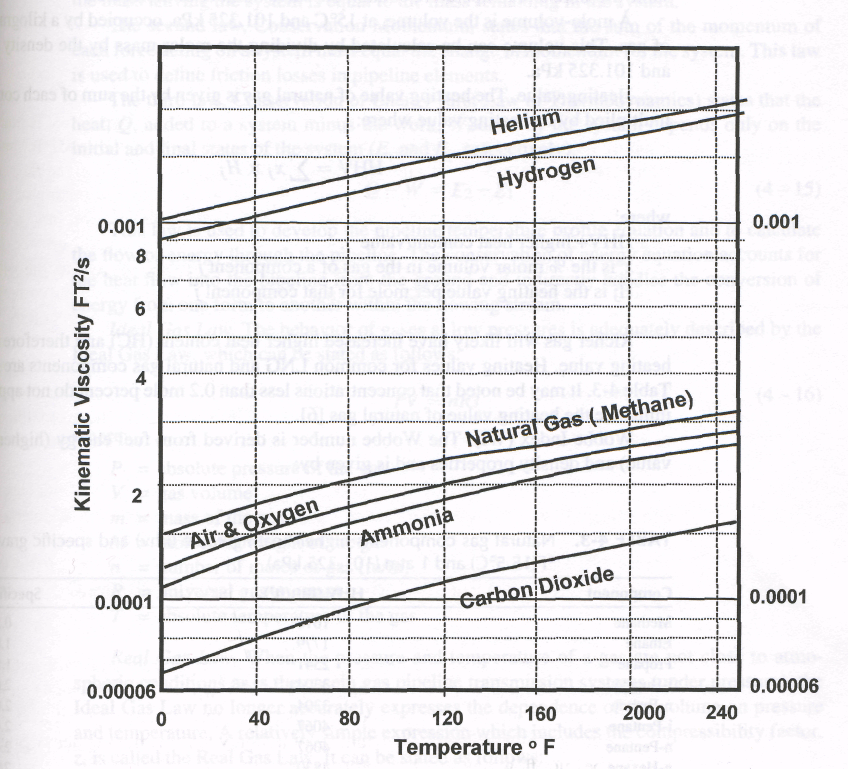
Kinematic viscosity, is the ratio of the absolute viscosity to the density. In SI, the normal unit of kinematic viscosity is the centistoke (0.01 stoke), which has units of square centimeters per second.
![]() ,
(4.12)
,
(4.12)
Kinematic viscosity of some gaseous fluids (in FT2/s) are indicated in Fig. 4-4.
Atomic and molecular weights: atoms and molecules have such minute masses that it would be cumbersome to perform engineering calculations using their masses in standard units. For this reason, the atomic weight of oxygen is arbitrarily considered to be exactly 16 U. The atomic weight of each of the other elements has been determined relative to that of oxygen. By procedures involving density measurements or chemical reactions, atomic weights have been determined for all the elements.
The approximate molecular weight or a molecule is me sum or me atomic weights of each component multiplied by the number of atoms in each molecule. For example, the molecular weight of propane (C3Hg) is:
(3 x 12.01) + (8 x 1.008) = 44.09
There is a small variance between the calculated molecular weight for certain molecules and that measured. This variance is a result of the compressibility of the molecules.
|
Figure 4-4. Kinematic viscosity of various gaseous fluids to temperature |
A kilogram-mole is the mass, in kilograms, equal to the molecular weight. For example, a kilogram-mole of oxygen is 32.00 kg. It can be shown that, for any gas, a kilogram-mole contains 6.05 x 1026 molecules. By Avogadro's law, equal volumes of gases at the same pressure and temperature contain the same number of molecules.
A mole-volume is the volume, at 15°C and 101.325 kPa, occupied by a kilogram-mole of gas. This volume can be calculated by dividing the molar mass by the density at lit and 101.325 kPa.
Heating value. The heating value of natural gas is given by the sum of each component multiplied by its heating value where:
![]() ,
(4.13)
,
(4.13)
where:
HHV+ higher heat content/value
xj is the % molar volume in the gas of a component j
Hj is the heating value per mole for that component j
Richer gas will likely have increased higher heat content (HC) and therefore a higher heating value. Heating values for common LNG and natural gas components are given in Table 4-1. It may be noted that concentrations less than 0.2 mole percent do not appreciably influence the heating value of natural gas.
Table 4-1. Natural gas components higher heating value (hhv) and specific gravity at 60 °F(1 5.5°Q and 1 atm (1 01 .325 kPa)
Component |
HHV (Btu/ft3) |
Specific Gravity |
Methane |
1016 |
0.555 |
Ethan |
1779 |
1.0405 |
Propane |
2541 |
1.5256 |
i-Butane |
3304 |
2.0111 |
n-Butane |
3304 |
2.0111 |
i-Pentane |
4067 |
2.4965 |
n-Pentane |
4067 |
2.4965 |
n-Hexane |
4830 |
2.9817 |
N2 |
- |
0.9692 |
CO2 |
- |
1.5253 |
Wobbe Index (WI): The Wobbe number is derived from fuel energy (higher heating value) and density properties and is given by:
![]() ,
(4-14)
,
(4-14)
where:
HHV = higher heating value
SG = specific gravity of fuel with reference to air
Absolute and gauge pressures. Absolute pressure is the pressure of a fluid when compared with the pressure in a vacuum. Gauge pressure is measured by a pressure gauge and is equal to the absolute pressure minus the atmospheric pressure.
Gas laws can provide the required relationship between density and pressure and temperature. Laws of conservation of mass, momentum, and energy can be applied.
Physical Laws. The determination of facilities requirements rely on use of mathematical formulae developed from general physical laws:
The first law, Conservation of Mass, states that the mass going into the system minus the mass leaving the system is equal to the mass remaining in the system.
The second law, Conservation Momentum, states that the sum of the momentum of each force acting on a system must equal the change in momentum for the system. This law is used to define friction losses in pipeline elements.
The third law, Conservation of Energy (first Law of Thermodynamics) states that the heat, Q, added to a system minus the work, W, done by the system depends only on the initial and final states of the system (E1 and E2, respectively).
![]() ,
(4-15)
,
(4-15)
This law is used to develop the pipeline temperature profile equation and to calculate the flow of energy through the pipeline. The conservation of energy equation accounts for the heat flow into the pipeline from the ground and indirectly handles the conversion of energy from one form to another within the flowing stream.
Ideal Gas Law. The behavior of gases at low pressures is adequately described by the Ideal Gas Law, which can be stated as follows:
PV = nRT (4.16)
where:
P = absolute pressure of the gas
V = gas volume
m = mass of the gas
M - molecular weight of the gas
n = number of moles of gas (m/m)
R = universal gas constant
T = absolute temperature of the gas
Real Gas Law. When the pressure and temperature of a gas are not close to atmospheric conditions as is the casein gas pipeline transmission systems (under pressure), the Ideal Gas Law no longer accurately expresses the dependence of the volume on pressure and temperature. A relatively simple expression which includes the compressibility factor, z, is called the Real Gas Law. It can be stated as follows:
PV=znRT (4-17)
where z is less than or equal to 1.0 and depends on the composition of the gas.
Another statement of the Real Gas Law which is used to calculate density is:
![]() ,
(4-18)
,
(4-18)
Density and Compressibility Factor. The gas density, p, can be described by thet Gas Law and the Equation of State. Starling and Han developed a commonly used I mulation called BWRS (Benedict-Webb-Rubin-Starling). The calculated density canti be substituted into the Real Gas Law to obtain z. The BWRS formulation of the Equal of State is discussed in the book, "Fluid Thermodynamic Properties for Light Petrole Systems" by Kenneth E. Starling. Other Equations of State which can be used to calcu! compressibility are Redlich-Kwong, Peng-Robinson, and Lee-Kessler. For full details the development of various equation of states, refer to reference [8].
If the subscript, o, represents the properties of a gas at a standard condition, the pi sure, volume, temperature, and compressibility of the same gas at other conditions can calculated as follows:
![]() ,
(4-19)
,
(4-19)
Density and viscosity of a compressible fluid are temperature-dependent. A higher temperature can cause a decrease in viscosity and density. Hence, a change in flow temperature can be more significant than indicated by any single equation. For a given flow, a temperature causes greater pressure loss in the pipe, and a higher temperature and pressure may occur at the compressor suction. The higher compression ratio and s temperature will both contribute to additional power requirement and greater dist temperature. Furthermore, the increased discharge temperature and decreased pressure crease the actual suction flow to the compressor and will likely decrease the compressor: efficiency. This will further raise the power required and the discharge temperature. W sufficient downstream cooling, lower pressures and higher temperatures will occur suction of the next station. Until sufficient cooling occurs, the downstream temperature the fluid will continue causing greater inefficiencies. This condition can be corrects coolers in the pipeline. In most cases, however, the heat transfer to the ground is sufficient to avoid serious problems, and cooling equipment is not required. For large diameter lines, cooling may become economical or necessary.
For two systems with different diameters but the same burial depth, initial temperature and similar flow conditions (i.e., at the same percentage of maximum flow capacity); the larger diameter pipe will retain its temperature for a greater distance than the smaller diameter. The mass flow rate is proportional to inside pipe diameter to the 2.5 power; I a greater length is required to cool the larger diameter pipe to a common temperature would be required to cool a smaller diameter pipe.
The following thermodynamic properties are considered in flow and temperature profile calculations.
compressibility factor
heat capacity at constant pressure
Joule-Thomson coefficient
isentropic temperature exponent
In some instances, it is possible to assume an isothermal flow, in which case it is necessary to consider only the momentum equation to determine pressure losses. When it is necessary to calculate the temperature profile along the pipeline, the energy equation as well as the momentum equation must be solved. Ignoring frictional effects, the energy equation can be written as:
![]() ,
(4-20)
,
(4-20)
where:
J = Joule-Thompson coefficient
Cp = Specific heat of gas
Qm = Heat loss per unit mass of the flowing gas
The temperature drop between two points is given by:
ΔT = ΔTc+ΔTj (4-21)
where:
ΔT = total temperature drop
ΔTc, = Total temperature drop due to conduction (or convection)
ΔTj. = Total temperature drop due to Joule-Thompson effect
Also depending on the extent of elevation change, ΔTc due to expansion and/or compression of gas moving up and down an elevation change can be added to the above equation 4-21.