

Radio Altimeter Inputs
The TCAS computer gets radio altitude from radio altimeter 1 and 2 transceivers although only one input is necessary for TCAS operation. The data is used by the TCAS computer to calculate some sensitivity levels.
At approximately 1700 feet, the TCAS computer uses radio altitude together with barometric altitude to determine intruders that are on the ground and therefore no threat to the TCAS airplane.
At 1000 feet radio altitude, the TCAs computer inhibits
resolution advisories and TA ONLY will show on the NDs.
TCAS Inputs from ADIRU
The left ADIRU supplies these inputs to the TCAS computer:
Airplane roll attitude
Airplane pitch attitude
Airplane heading.
NOTE: Airplane heading is the only ADIRU input used by the TCAS computer.
NOTE: These inputs are not used by the TCAS computer at this time.
TCAS Outputs to DEUs
The TCAS computer supplies resolution advisory (RA) and traffic advisory (TA) data to the DEUs. This includes all traffic data for TCAS displays.
TCAS Outputs to the FDAU
The FDAU receives the same TCAS data that goes to the DEUs.
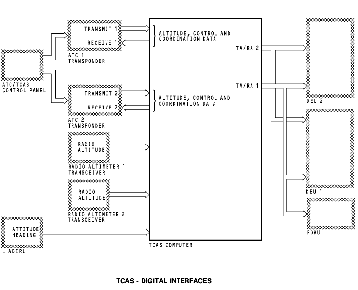
TCAS - DIGITAL INTERFACES
Purpose
The TCAS computer is the main component of the TCAS. It controls these functions:
Surveillance
Tracking
Advisory
Air-to-air maneuver coordination.
The TCAS computer sends signals which tell the flight crew to make one of these maneuvers:
Keep the current flight plan
Make flight maneuvers to prevent a possible collision with other airplanes in the area.
Physical Description
The TCAS computer is a 6 MCU size unit. It weighs 28 lbs (11.3 kg).
Functional Description
The TCAS computer transmits 1030 MHz pulse-coded interrogation signals. It receives 1090 MHz pulse-coded reply signals from intruder airplanes with an ATC transponder.
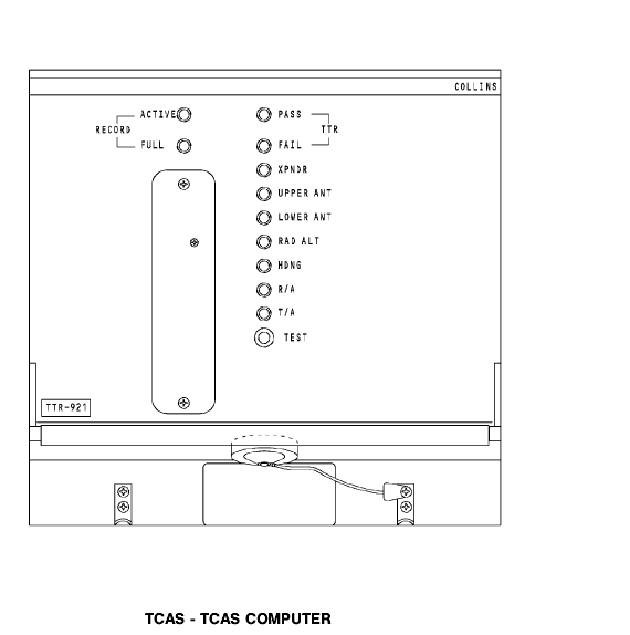
Front Panel LED Indications
These are the status light emitting diodes (LEDs):
A green PASS to show that there is no TCAS computer
failure
A red FAIL to show a TCAS computer failure
A red XPNDR to show an ATC transponder interface failure
A red UPPER ANT to show a top TCAS antenna failure
A red LOWER ANT to show a bottom TCAS antenna failure
A red RAD ALT to show no radio altitude data from the RA
A red HDNG to show no heading data from the ADIRU
A red R/A to show a DEU display function failure
The red T/A does not operate.
Front Panel Self-Test
You push the test switch on the front panel to start a test of the TCAS. The LED indications come on to show system status.
Performance Management Recording
The TCAS computer has a slot for a Personal Computer
Memory Card International (PCMCIA) card. The recorder
function provides the capability to store information about
TCAS events for post-flight analysis. These are the RECORD light emitting diodes (LEDs):
An ACTIVE to show card recording
A FULL to show card recording complete.
Front Panel Connectors
There is one connector on the front panel. You use it to load revised software and for automated test equipment.
TCAS - ATC/TCAS CONTROL PANEL
General
The ATC/TCAS control panel controls the TCAS computer.
Function Select Switch
You use the function select switch to select one of these TCAS modes:
TA/RA mode. The displays show all targets. This is the
normal mode of operation for TCAS.
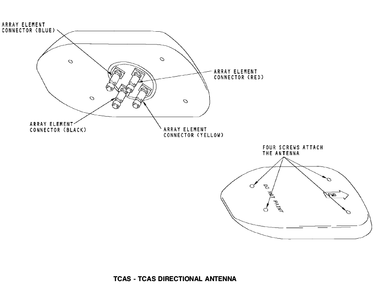
DIRECTIONAL ANTENNA
Physical Description
The directional antenna is a phased array antenna. There are
four array elements on the antenna. Each element has a color
coded connector. The TCAS computer sends transmit
interrogation signals to the array elements with different
phases. This makes the interrogation signal directional.
To attach the antenna cables, connect each coaxial cable with the array element connector that has the same color band.
Four screws attach the antenna to the airplane. The radiation side of the antenna shows FWD and DO NOT PAINT.
CAUTION: DO NOT PAINT THE RADIATION SURFACE OR THE
BACKPLATE OF THE ANTENNA. PAINT DOES NOT
PERMIT THE ANTENNA TO RADIATE OR RECEIVE
RF SIGNALS.
CAUTION: TO PREVENT DAMAGE TO THE ANTENNA CABLES, DO NOT PULL ON THEM.
Training Information Point
An antenna connection includes the coax cable and an antenna element. The TCAS computer checks the resistance of each antenna connection at power-up. The TCAS computer reports an antenna fault when it detects that the resistance of the connection is out of range. If you do not connect the coax cable to the correct element, the TCAS computer reports an antenna fault.
TCAS - FUNCTIONAL DESCRIPTION
General
The TCAS computer transmits interrogations to and receives
replies from other airplanes. Airplanes that are tracked by
TCAS are called targets. The TCAS computer uses these
replies and data from other airplane systems to calculate if a target is a collision threat. The TCAS computer can communicate with other airplanes that have TCAS. The two TCAS computers can use the shared data to perform coordinated maneuvers and avoid potential collisions.
The TCAS computer also gets analog and digital inputs from other airplane systems. These inputs control TCAS and provide data for TCAS to track intruders. The TCAS computer sends display data to the common display system (CDS) display electronic units (DEUs).
The TCAS computer has these circuits:
Input/output (I/O)
Speech Processor
Central processing unit (CPU) and memory
Suppression circuit
Signal Processor
Receiver
Transmitter
Beam steering and attenuator
BITE.
I/O
The I/O circuit gets this on-board airplane systems data:
Magnetic heading data from the left ADIRU
Coordination and control data from the ATC transponder system
Barometric altitude from the left or right ADIRU from the
active ATC
Radio altitude from the radio altimeters
Resolution advisory status from the DEUs
Landing gear down discrete from the landing gear lever
switch
Aural inhibit discrete interface with the GPWC
Aural inhibit discrete interface with the weather radar
Air/ground data from the PSEU.
Program pins set these parameters in the TCAS computer:
Altitude limits
Aural warning volume levels
Self test inhibits
Standby on ground
Intruders on ground disabled.
The I/O circuits send this data to the CPU.
CPU
The CPU gets the data from the inputs of the I/O and puts it into
memory. The CPU combines the input data and the data it
receives from the signal processor. The CPU makes the
necessary calculations for the TCAS displays and aural
messages.
The CPU sends TCAS display data to the CDS DEUs. It shows on these indicators:
Attitude indicators (AI)
Navigation display (ND)
The CPU sends the display data to the flight data acquisition unit (FDAU).
It also sends signals through the speech processor circuits to the REU to make TCAS aurals.