

16.2.2. Angle of attack of airplane zero lift
The value of angle of attack of airplane zero lift
![]() is included in general expression for the airplane lift coefficient
(16.7) and is calculated under the formulae:
is included in general expression for the airplane lift coefficient
(16.7) and is calculated under the formulae:
![]() ,
(16.12)
,
(16.12)
![]() ,
(16.13)
,
(16.13)
where
![]() ,
,
![]() ,
,
![]() ,
,
![]() - angles of attack of zero lift of the fuselage, wing, horizontal
tail and engine nacelle in the airplane system. At that, angle of
fuselage zero lift corresponds to the angle of isolated fuselage zero
lift
- angles of attack of zero lift of the fuselage, wing, horizontal
tail and engine nacelle in the airplane system. At that, angle of
fuselage zero lift corresponds to the angle of isolated fuselage zero
lift
![]() ,
angle of engine nacelle zero lift - to angle of the engine nacelle
axis installation relatively to the fuselage axis
,
angle of engine nacelle zero lift - to angle of the engine nacelle
axis installation relatively to the fuselage axis
![]() (at axis deflection upwards
(at axis deflection upwards
![]() ).
).
The angles of attack
and
![]() also depend on airplane configuration:
also depend on airplane configuration:
- for the normal configuration:
![]() ,
,
 ;
(16.14)
;
(16.14)
- for the canard configuration:
 ,
,
![]() ,
(16.14)
,
(16.14)
where
![]() and
and
![]() - angles of zero lift for the isolated wing and horizontal tail
(usually
- angles of zero lift for the isolated wing and horizontal tail
(usually
![]() ),
),
![]() and
and
![]() - angles of wing and horizontal tail setting relatively to the
fuselage axis;
- also can be the angle of pivot stabilizer deflection.
- angles of wing and horizontal tail setting relatively to the
fuselage axis;
- also can be the angle of pivot stabilizer deflection.
16.2.3. Maximum airplane lift
Maximum lift and critical angle of attack met to
it are the parameters determining airplane performance. The precisely
values of the maximum lift coefficient
![]() and critical angle of attack
and critical angle of attack
![]() now can be obtained only in experimental way.
now can be obtained only in experimental way.
For the airplane with high-aspect-ratio wings
![]() values
are calculated under the formula
values
are calculated under the formula
![]() ,
(16.15)
,
(16.15)
where
![]() - characteristic of the wing airfoil; the factors
- characteristic of the wing airfoil; the factors
![]() take into account influence of the airfoil shape, sweep angle, wing
taper and flight Mach
take into account influence of the airfoil shape, sweep angle, wing
taper and flight Mach
![]() number.
number.
For the airplane with low-aspect-ratio wing
![]() the maximum lift coefficient is calculated by the formula
the maximum lift coefficient is calculated by the formula
![]() .
(16.16)
.
(16.16)
The critical angle of attack of the airplane with the high-aspect-ratio wing and with low-aspect-ratio wing without the account of non-linear effects is determined as follows
 ,
(16.17)
,
(16.17)
where
![]() and
- airplane characteristic.
and
- airplane characteristic.
The construction of ratio
![]() by known values
,
and
is shown in fig. 16.2.
by known values
,
and
is shown in fig. 16.2.
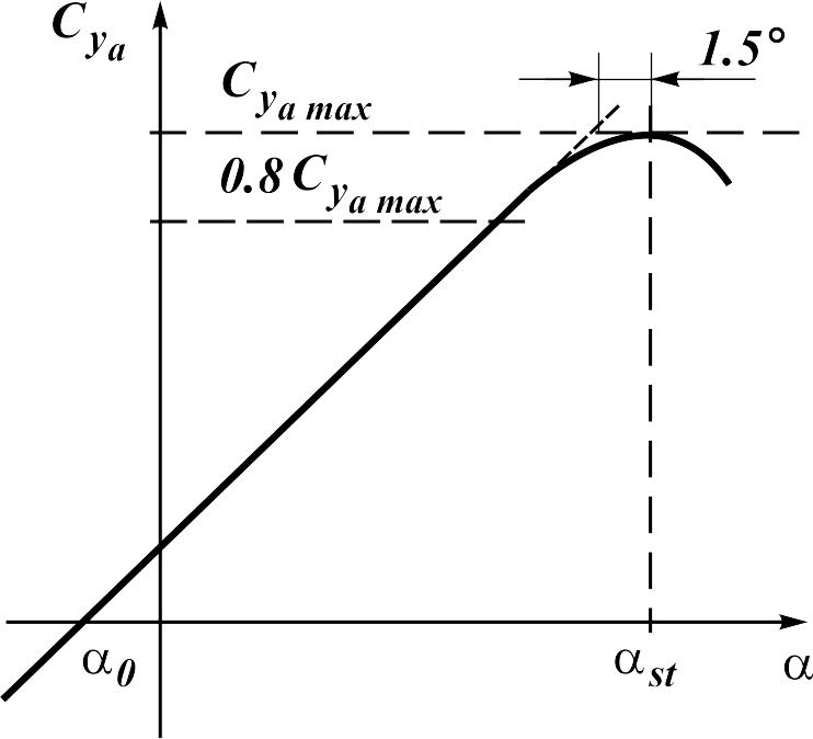
Fig. 16.2. A construction of ratio
16.3. Polar of a aircraft.
The origin of inductive drag is connected to formation of a vortex wake behind a skew field at presence of lift. However on a wing with geometric twist a vortex wake and inductive drag can exist when the summarized lift of a wing will be equal to zero.
The factor of the airplane induced drag can be presented in the following form:
![]() ,
(16.18)
,
(16.18)
where the first item concerns to the airplane,
which basic elements creating lift have horizontal plane of symmetry
and lifting surfaces set under zero angle to the fuselage axis;
![]() - factor of induced drag at
- factor of induced drag at
![]() .
.
The additional items, as a rule, introduce the
minor contribution to induced drag for majority of airplanes in
flight configurations, i.e. it is possible to accept
![]() and
and
![]() ,
and for such case
,
and for such case
![]() ,
,
where
![]() - polar pull-off coefficient.
- polar pull-off coefficient.
At subsonic Mach numbers
![]() the value
is determined as follows
the value
is determined as follows
![]() ,
(16.19)
,
(16.19)
where
![]() - wing aspect ratio with ventral part.
- wing aspect ratio with ventral part.
Parameter
![]() depends on the cross section shape of the wing - fuselage
configuration. The factor
depends on the cross section shape of the wing - fuselage
configuration. The factor
![]() takes into account the horizontal tail contribution into induced
drag.
takes into account the horizontal tail contribution into induced
drag.
For isolated wing with the optimum (elliptical)
law of circulation distribution spanwise we shall have
![]() ,
,
![]() ,
,
![]() and in accordance with (16.19) we come to known result
and in accordance with (16.19) we come to known result
![]() .
.
In a supersonic flow
![]() the polar pull-off coefficient is calculated as follows
the polar pull-off coefficient is calculated as follows
![]() ,
(16.20)
,
(16.20)
where
![]() - relative factor of sucking force realized on the fuselage nose at
absence of the nose air intake, on wing subsonic leading edges and
horizontal tail.
- relative factor of sucking force realized on the fuselage nose at
absence of the nose air intake, on wing subsonic leading edges and
horizontal tail.
The characteristic ratio of the polar pull-off coefficient on Mach number is shown in fig. 16.3. Let's note, that the polar pull-off coefficient practically does not vary at subsonic speeds, at supersonic speeds it is increased, because the derivative of the lift coefficient decreases.
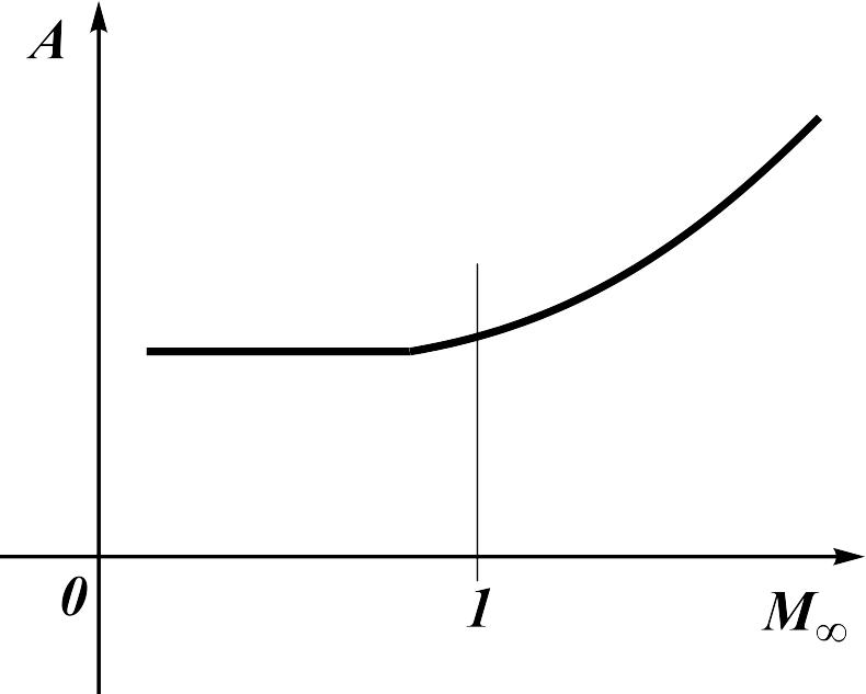
Fig. 16.3. Polar pull-off factor on Mach number ratio
It is necessary to take into account the additional drag which is conditioned by angles of attack influence onto profile drag and wave crisis happening on the wing for the airplane polar construction.
The updated expression for calculation of a polar looks like
![]() .
(16.21)
.
(16.21)
The increment of the profile drag factor with angles of attack increasing zis estimated as follows
![]() ,
,
![]() .
(16.22)
.
(16.22)
The second source of additional drag is connected
to local shock waves happened on the wing at values of a lift
coefficient
![]() which is going out of subsonic speeds range, which boundary is
determined by ratio
which is going out of subsonic speeds range, which boundary is
determined by ratio
![]() (fig. 6.22). The additional drag
(fig. 6.22). The additional drag
![]() is determined by the formula
is determined by the formula
![]() ,
(16.23)
,
(16.23)
where
![]() is determined by the formula (6.23).
is determined by the formula (6.23).
The account of additional drag results in the
characteristic fork of polars constructed for various flight numbers
.
The higher the number
,
the smaller values
of the deviation from the subsonic polar. In transonic flow area (![]() )
already at
the wave drag appears and the polar top displaces to the right.
)
already at
the wave drag appears and the polar top displaces to the right.
The characteristic polar types are shown in fig. 16.4 and fig. 16.5.
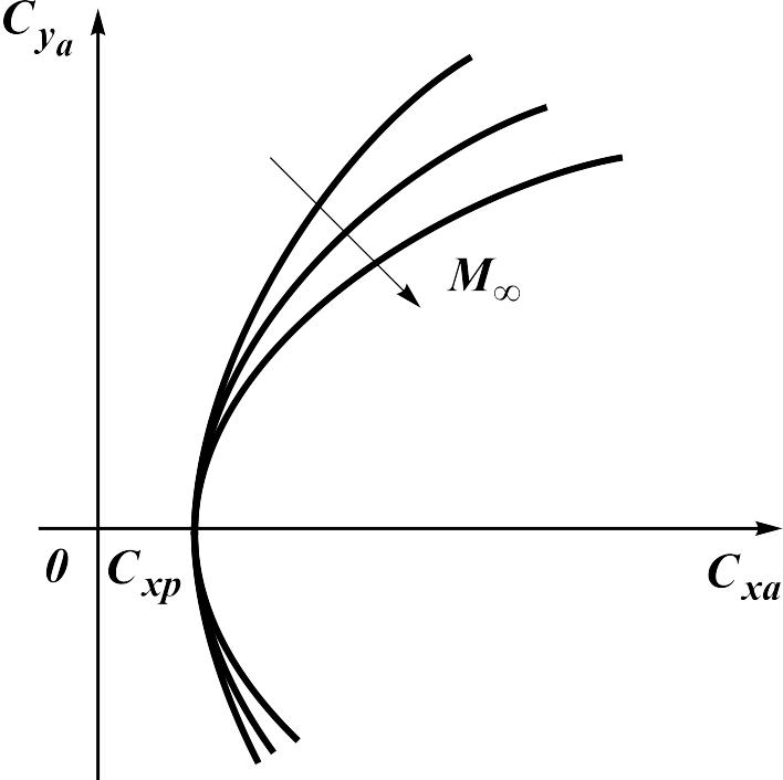
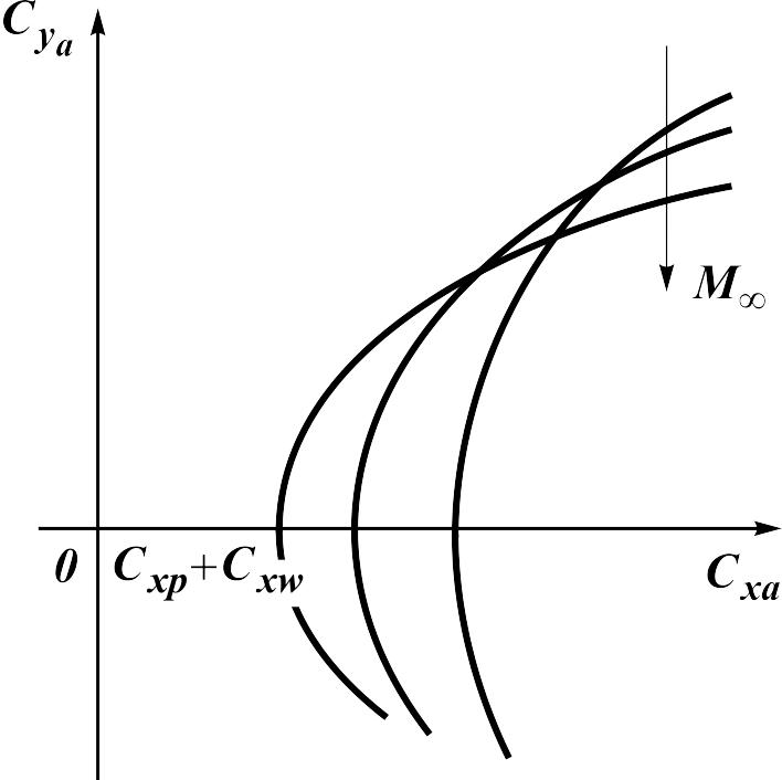
Fig. 16.3. The airplane polar in subsonic range of speeds |
Fig. 16.4. The airplane polar in supersonic range of speeds |
By known values of factors
and
![]() also calculate airplane lift-to-drag ratio
also calculate airplane lift-to-drag ratio
![]() .
The value of maximum quality is determined with the help of
expression
.
The value of maximum quality is determined with the help of
expression
![]() .
.