

Section 3. Aerodynamics of the aircraft
Topic 15. Mutual influence of lifting surfaces And fuselage
Practically all elements of the aircraft except wing either do not create lift at all or create it at some flight angles of attack, but this lift is insignificant in comparison with wing lift. The aircraft drag consists of drag of its separate parts with taking into account their mutual influence.
Let's consider the problem of wing and fuselage interference in details.
15.1. Drag of the wing - fuselage system
The drag of the wing - fuselage system is much more than sum of separately taken drags of wing and fuselage. Jointing of wing and fuselage into the single whole causes an additional drag. This drag is called as a hazard interference. Let's consider separately profile and wave drag of the wing-fuselage system.
15.1.1. Profile drag
The force of profile drag consists of three items:
![]() ,
(15.1)
,
(15.1)
where
![]() - profile drag force of an isolated wing composed from consoles;
- profile drag force of an isolated wing composed from consoles;
![]() - profile drag force of the fuselage;
- profile drag force of the fuselage;
![]() - additional drag force caused by an interference.
- additional drag force caused by an interference.
If the area
of a wing with ventral part
![]() is accepted as the characteristic area for the wing - fuselage system
and
is accepted as the characteristic area for the wing - fuselage system
and
![]() ,
we shall receive
,
we shall receive
![]() ,
(15.2)
,
(15.2)
where
![]() - coefficient of flow deceleration before the wing (influence of the
fuselage),
- coefficient of flow deceleration before the wing (influence of the
fuselage),
![]() ,
,
![]() - ratio of the areas of an isolated wing and of fuselage midsection
to the characteristic area.
- ratio of the areas of an isolated wing and of fuselage midsection
to the characteristic area.
It has be
noticed that profile drag of an isolated wing
![]() is calculated at
is calculated at
![]() .
.
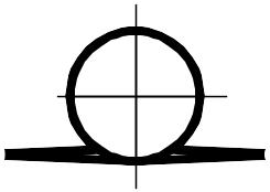
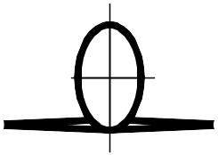
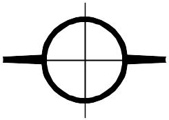
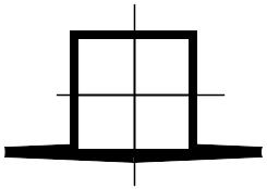
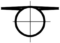
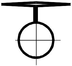
Fig.
15.1. Diffuser effect in a place of wing and fuselage jointing: a)
- area of diffuser flow; b)
- fillets at wing and fuselage jointing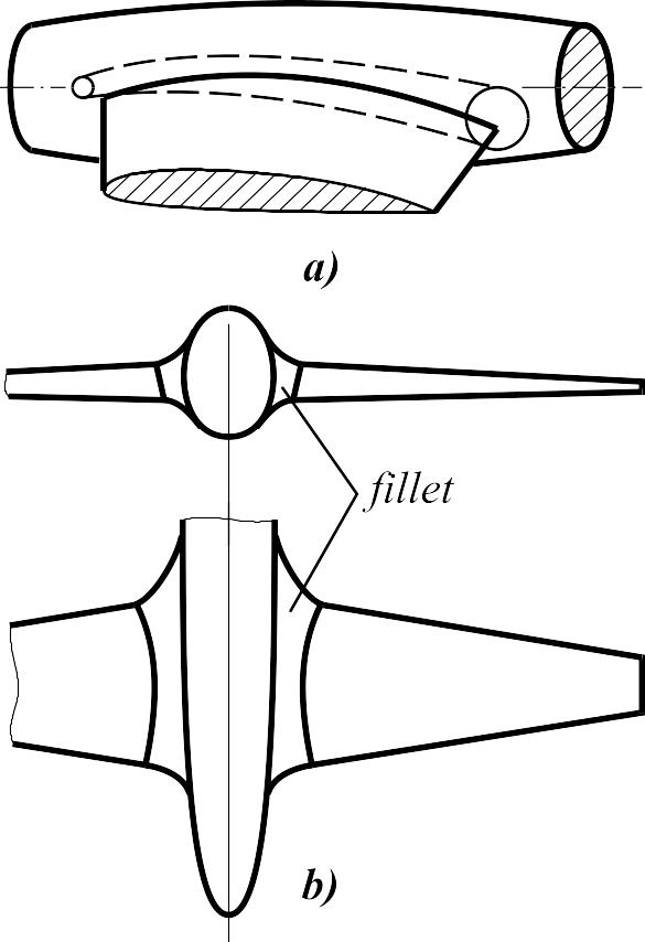
![]() in these cross-sections.
All this results in drag increasing as
due to friction forces as due to pressure forces.
To decreasing the hazard interference the so-called fillets
(fairings) are used (Fig. 15.1, b). It is possible greatly reduced
the hazard interference at correct selection of fillets.
in these cross-sections.
All this results in drag increasing as
due to friction forces as due to pressure forces.
To decreasing the hazard interference the so-called fillets
(fairings) are used (Fig. 15.1, b). It is possible greatly reduced
the hazard interference at correct selection of fillets.
For a factor of additional drag we have
![]() ,
(15.3)
,
(15.3)
where
![]() - interference factor; generally depends on lifting surface location
(wing, horizontal tail) on a fuselage and shape of fuselage cross
section;
- interference factor; generally depends on lifting surface location
(wing, horizontal tail) on a fuselage and shape of fuselage cross
section;
![]() - area of a wing occupied by a fuselage (
- area of a wing occupied by a fuselage (![]() or
or
![]() ).
).
From a view point of drag the interference between a wing and fuselage (tail unit and fuselage) is negative. The researches show, that such interference is the most unfavorable for low-wing airplane, least unfavorable - for high-wing plane.
It is
tentatively possible to assume interference factors
which are listed in table 15.1 irrespectively from numbers
![]() .
.
Table 15.1. Interference factors
Wing location |
|
Wing location |
|
|
|
|
|
|
|
|
|
|
|
|
|
It is
possible to consider (with taking into account fairings
installation), that at thin wing (![]() )
installation on a fuselage cylindrical surface by the mid-wing scheme
)
installation on a fuselage cylindrical surface by the mid-wing scheme
![]() .
It is necessary to note, that in some configurations the diffuser
effect can be more at wing installation by the high-wing scheme. It
is possible to consider the diffuser effect as equal to zero
at the horizontal tail installation onto vertical according to
Tee-tail unit scheme, but at that it is necessary to displace the
mutual position of maximum thickness of vertical and horizontal tail
airfoils.
.
It is necessary to note, that in some configurations the diffuser
effect can be more at wing installation by the high-wing scheme. It
is possible to consider the diffuser effect as equal to zero
at the horizontal tail installation onto vertical according to
Tee-tail unit scheme, but at that it is necessary to displace the
mutual position of maximum thickness of vertical and horizontal tail
airfoils.
15.1.2. Wave drag.
The
interference problem gains the special sharpness at configuration of
a high-speed aircraft. At high flight speeds there can be so-called
wave interference, i.e. the additional wave drag, which is caused by
occurrence of shock waves in a place of the wing and fuselage joint.
The unsuccessful joint of wing with fuselage can result in
substantial drag growth, decreasing of critical number
![]() and more intense growth of drag after occurrence of wave crisis.
and more intense growth of drag after occurrence of wave crisis.
Analogously to profile drag it can be written as
![]() (15.4)
(15.4)
and
![]() .
(15.5)
.
(15.5)
The factor
![]() should be determined at
should be determined at
![]() .
In particular
.
In particular
![]() .
.
The additional wave drag occurs as a result of interaction of two flows about the fuselage and the wing.
![]() ;
;
![]() ;
;
![]() ,
(15.6)
,
(15.6)
where the
factors
![]() and
and
![]() also depend on the wing plan form:
also depend on the wing plan form:
![]() ,
,
![]() - fuselage - swept wing;
- fuselage - swept wing;
![]() ,
,
![]() -
fuselage - delta wing.
-
fuselage - delta wing.
Number
![]() - critical number
of the fuselage - wing system. It will be less than critical number
of an isolated wing and fuselage. It is possible to assume
- critical number
of the fuselage - wing system. It will be less than critical number
of an isolated wing and fuselage. It is possible to assume
![]() taking into account the effect of flows interaction.
taking into account the effect of flows interaction.
Effective
way to decrease an additional wave drag - using of '' area-rule ".
Using of " area-rule " results into wave drag drop first of
all in the zone of transonic speeds (![]() )
(Fig. 15.2).
)
(Fig. 15.2).
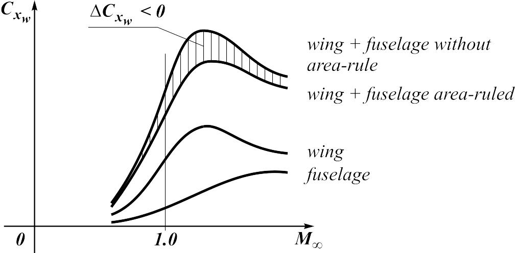
Fig. 15.2. Wave drag of fuselage - wing system.
Fig.
15.3.
There is a generalization of subsonic area-rule to supersonic speeds (supersonic area-rule).
15.2. Lift of the wing - fuselage system
Let's
consider a wing - fuselage system put into flow under an angle of
attack
![]() .
For simplification we shall assume, that the fuselage is a body of
revolution close to cylindrical, and the wing is installed on it by
the mid-wing scheme with angle
.
For simplification we shall assume, that the fuselage is a body of
revolution close to cylindrical, and the wing is installed on it by
the mid-wing scheme with angle
![]() .
.
Within borders of the linear theory the general configuration wing - fuselage can be presented as a sum of two schemes:
Fig. 15.4.
Fig.
15.5.
![]()
where
![]() - lift coefficient of the fuselage - wing system with a symmetrical
airfoil at a zero setting angle (
- lift coefficient of the fuselage - wing system with a symmetrical
airfoil at a zero setting angle (![]() ,
fuselage with a straight-line axis),
,
fuselage with a straight-line axis),
![]() - lift coefficient of the fuselage - wing system with aerodynamic and
geometric twist and with setting angle (
- lift coefficient of the fuselage - wing system with aerodynamic and
geometric twist and with setting angle (![]() ,
fuselage with curved axis).
,
fuselage with curved axis).
Let's consider lift of these schemes.
Scheme"
![]() ".
Let's write down lift as a sum
".
Let's write down lift as a sum
![]() ,
(15.7)
,
(15.7)
where first
two items
![]() and
and
![]() are also concern to an isolated fuselage with a straight-line axis
(in horizontal plane of symmetry) and flat wing with a symmetrical
airfoil;
are also concern to an isolated fuselage with a straight-line axis
(in horizontal plane of symmetry) and flat wing with a symmetrical
airfoil;
![]() - additional lift arising on the wing because of fuselage influence;
- additional lift arising on the wing because of fuselage influence;
![]() - additional lift arising on a fuselage because of wing influence.
- additional lift arising on a fuselage because of wing influence.
Obviously,
the sum
![]() represents lift of a wing set on the fuselage.
represents lift of a wing set on the fuselage.
We accept
 ,
,
![]() ,
,
where
![]() and
and
![]() - interference factors for a flat wing with a symmetrical airfoil and
fuselage having a horizontal plane of symmetry (at
- interference factors for a flat wing with a symmetrical airfoil and
fuselage having a horizontal plane of symmetry (at
![]()
![]()
![]() ).
).
Taking in accout it is obtained
![]() .
(15.8)
.
(15.8)
If to pass to lift coefficients
![]() ,
,
![]() ,
,
![]() ,
,
where
- characteristic area;
![]() - dynamic pressure before the wing, we shall receive:
- dynamic pressure before the wing, we shall receive:
![]() ,
(15.9)
,
(15.9)
where
![]() - factor of flow deceleration before a wing (fuselage influence),
,
- ratio of the isolated wing area and fuselage mid-section area to
the characteristic area
.
At it lift coefficient of an isolated wing
- factor of flow deceleration before a wing (fuselage influence),
,
- ratio of the isolated wing area and fuselage mid-section area to
the characteristic area
.
At it lift coefficient of an isolated wing
![]() is determined at
.
is determined at
.
Scheme
"![]() ".
Let's write down lift as a sum
".
Let's write down lift as a sum
![]() ,
(15.10)
,
(15.10)
where first
two items
![]() and
and
![]() - characteristic of an isolated fuselage and wing at
- characteristic of an isolated fuselage and wing at
![]() ;
lift occur at the expense of camber of fuselage axis, camber of
airfoil, twist and angle of wing setting onto fuselage;
;
lift occur at the expense of camber of fuselage axis, camber of
airfoil, twist and angle of wing setting onto fuselage;
![]() - additional lift arising on a wing because of fuselage influence;
- additional lift arising on a wing because of fuselage influence;
![]() - additional lift arising on a fuselage because of wing influence.
- additional lift arising on a fuselage because of wing influence.
Here, as
well as for scheme "
",
the sum
![]() represents lift of a wing set on the fuselage.
represents lift of a wing set on the fuselage.
Let's write down similarly to the previous case
 ,
(15.11)
,
(15.11)
where
![]() and
and
![]() - interference factor for the wing - fuselage system at
.
- interference factor for the wing - fuselage system at
.
If, as well as in the previous scheme, we pass to lift coefficients, we shall receive
![]() .
(15.12)
.
(15.12)
Finally,
for the general scheme "![]() "
is obtained:
"
is obtained:
 (15.13)
Let's consider isolated elements:
Fuselage:
![]() .
.
Obviously
![]() ,
and
,
and
![]() .
.
Wing:
![]() .
.
Obviously
![]() ,
,
![]() .
.
Taking into account it, we obtain
 (15.14)
Let's consider the separate characteristic of a wing set on fuselage (w/f):
where
![]() and
and
![]() - characteristic of a wing in system with fuselage.
- characteristic of a wing in system with fuselage.
Now we can write in the same type form
![]() (15.15)
(15.15)
And finally for a wing - fuselage system
![]() ;
;
![]() ;
;
![]() ,
,
where a
derivative of a fuselage lift coefficient and angle of zero lift
undertake for an isolated fuselage
![]() and
and
![]() ;
the derivative of wing lift coefficient and angle of zero lift are
calculated under the formulas with taking into account the
interference factors
;
the derivative of wing lift coefficient and angle of zero lift are
calculated under the formulas with taking into account the
interference factors
![]() and
and
![]() .
.
The note: the shown dependence for the wing - fuselage system remains valid for a system a horizontal tail-fuselage located on a fuselage ahead of a wing (canard scheme).
For normal
scheme, when horizontal tail is located behind the wing it is
necessary to take into account a wing influence on horizontal tail in
addition to the interference of horizontal tail and fuselage. In this
case horizontal tail is streamlined under the smaller angle of attack
equal to
![]() .
.
Let's
consider the characteristic of horizontal tail
![]() located on the fuselage similar to the wing characteristic
located on the fuselage similar to the wing characteristic
![]() :
:
 .
.
Substituting here , we obtain for horizontal tail in the system of aircraft with normal scheme:
![]() ,
,
where the derivative of lift coefficient of horizontal tail and angle of zero lift are equal
![]()
and
 ;
;
![]() - angle of
the horizontal tail setting relatively to the fuselage axis; as a
rule, the symmetrical airfoil is installed on horizontal tail and
- angle of
the horizontal tail setting relatively to the fuselage axis; as a
rule, the symmetrical airfoil is installed on horizontal tail and
![]() .
Obviously, the wing lift in the system of a canard aircraft also
should be determined with accounting of flow downwash located ahead
of horizontal tail. Therefore, last expressions remain fair and for a
wing in the canard scheme after replacement of parameters of
horizontal tail on wing parameters.
.
Obviously, the wing lift in the system of a canard aircraft also
should be determined with accounting of flow downwash located ahead
of horizontal tail. Therefore, last expressions remain fair and for a
wing in the canard scheme after replacement of parameters of
horizontal tail on wing parameters.
Let's
consider interference factors
,
,
and
![]() .
Generally they depend on the ratio of fuselage midsection diameter
.
Generally they depend on the ratio of fuselage midsection diameter
![]() to wing span with ventral part
to wing span with ventral part
![]() ,
wing shape and fuselage cross-section, wing setting on fuselage
altitude and length, number
,
wing shape and fuselage cross-section, wing setting on fuselage
altitude and length, number
![]() and influence of the boundary layer. These dependencies are complex
and systematic data about them are absent in the literature. Most
essential ones, as researches show, are the dependencies from
and influence of the boundary layer. These dependencies are complex
and systematic data about them are absent in the literature. Most
essential ones, as researches show, are the dependencies from
![]() ,
shown in fig. 15.6.
,
shown in fig. 15.6.
Fig. 15.6.
Dependence of interference factors from
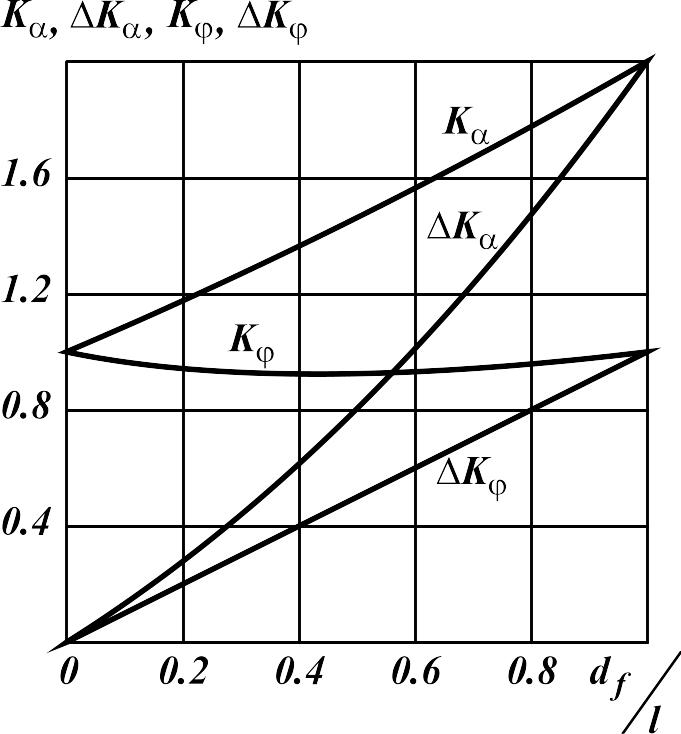
![]() ,
,
![]() ,
,
![]() ;
;
![]()
![]()
![]() .
.
The last three equalities are more exact than first three.
As we see, calculation of interference factors are reduced to definition of a factor .
Let's pass to consideration of mutual influence of a wing and fuselage.