

- •Features
- •1. Pin Configurations
- •2. Overview
- •2.1 Block Diagram
- •2.2 Pin Descriptions
- •2.2.3 Port A (PA7:PA0)
- •2.2.4 Port B (PB7:PB0)
- •2.2.5 Port C (PC7:PC0)
- •2.2.6 Port D (PD7:PD0)
- •2.2.7 RESET
- •2.2.8 XTAL1
- •2.2.9 XTAL2
- •2.2.10 AVCC
- •2.2.11 AREF
- •3. Resources
- •4. Data Retention
- •5. About Code Examples
- •6. AVR CPU Core
- •6.1 Overview
- •6.3 Status Register
- •6.3.1 SREG – AVR Status Register
- •6.4 General Purpose Register File
- •6.5 Stack Pointer
- •6.5.1 SPH and SPL – Stack Pointer High and Low Register
- •6.6 Instruction Execution Timing
- •6.7 Reset and Interrupt Handling
- •6.7.1 Interrupt Response Time
- •7. AVR Memories
- •7.1 Overview
- •7.3 SRAM Data Memory
- •7.3.1 Data Memory Access Times
- •7.4 EEPROM Data Memory
- •7.4.1 EEPROM Read/Write Access
- •7.4.3 Preventing EEPROM Corruption
- •7.5 I/O Memory
- •7.6 Register Description
- •7.6.1 EEARH and EEARL – EEPROM Address Register
- •7.6.2 EEDR – EEPROM Data Register
- •7.6.3 EECR – EEPROM Control Register
- •8. System Clock and Clock Options
- •8.1 Clock Systems and their Distribution
- •8.2 Clock Sources
- •8.3 Default Clock Source
- •8.4 Crystal Oscillator
- •8.6 External RC Oscillator
- •8.7 Calibrated Internal RC Oscillator
- •8.8 External Clock
- •8.9 Timer/Counter Oscillator
- •8.10 Register Description
- •8.10.1 OSCCAL – Oscillator Calibration Register
- •9. Power Management and Sleep Modes
- •9.1 Sleep Modes
- •9.2 Idle Mode
- •9.3 ADC Noise Reduction Mode
- •9.6 Standby Mode
- •9.7 Extended Standby Mode
- •9.8 Minimizing Power Consumption
- •9.8.1 Analog to Digital Converter
- •9.8.2 Analog Comparator
- •9.8.4 Internal Voltage Reference
- •9.8.5 Watchdog Timer
- •9.8.6 Port Pins
- •9.9 Register Description
- •9.9.1 MCUCR – MCU Control Register
- •10. System Control and Reset
- •10.1 Resetting the AVR
- •10.2 Reset Sources
- •10.2.2 External Reset
- •10.2.4 Watchdog Reset
- •10.3 Internal Voltage Reference
- •10.4 Watchdog Timer
- •10.5 Register Description
- •10.5.1 MCUCSR – MCU Control and Status Register
- •10.5.2 WDTCR – Watchdog Timer Control Register
- •11. Interrupts
- •11.1 Interrupt Vectors in ATmega32A
- •11.1.1 Moving Interrupts Between Application and Boot Space
- •11.2 Register Description
- •11.2.1 GICR – General Interrupt Control Register
- •12. I/O Ports
- •12.1 Overview
- •12.2 Ports as General Digital I/O
- •12.2.1 Configuring the Pin
- •12.2.2 Reading the Pin Value
- •12.2.3 Digital Input Enable and Sleep Modes
- •12.2.4 Unconnected pins
- •12.3 Alternate Port Functions
- •12.3.1 Alternate Functions of Port A
- •12.3.2 Alternate Functions of Port B
- •12.3.3 Alternate Functions of Port C
- •12.3.4 Alternate Functions of Port D
- •12.4 Register Description
- •12.4.1 SFIOR – Special Function I/O Register
- •12.4.2 PORTA – Port A Data Register
- •12.4.3 DDRA – Port A Data Direction Register
- •12.4.4 PINA – Port A Input Pins Address
- •12.4.5 PORTB – Port B Data Register
- •12.4.6 DDRB – Port B Data Direction Register
- •12.4.7 PINB – Port B Input Pins Address
- •12.4.8 PORTC – Port C Data Register
- •12.4.9 DDRC – Port C Data Direction Register
- •12.4.10 PINC – Port C Input Pins Address
- •12.4.11 PORTD – Port D Data Register
- •12.4.12 DDRD – Port D Data Direction Register
- •12.4.13 PIND – Port D Input Pins Address
- •13. External Interrupts
- •13.1 Register Description
- •13.1.1 MCUCR – MCU Control Register
- •13.1.2 MCUCSR – MCU Control and Status Register
- •13.1.3 GICR – General Interrupt Control Register
- •13.1.4 GIFR – General Interrupt Flag Register
- •14. 8-bit Timer/Counter0 with PWM
- •14.1 Features
- •14.2 Overview
- •14.2.1 Registers
- •14.2.2 Definitions
- •14.3 Timer/Counter Clock Sources
- •14.4 Counter Unit
- •14.5 Output Compare Unit
- •14.5.1 Force Output Compare
- •14.5.2 Compare Match Blocking by TCNT0 Write
- •14.5.3 Using the Output Compare Unit
- •14.6 Compare Match Output Unit
- •14.6.1 Compare Output Mode and Waveform Generation
- •14.7 Modes of Operation
- •14.7.1 Normal Mode
- •14.7.2 Clear Timer on Compare Match (CTC) Mode
- •14.7.3 Fast PWM Mode
- •14.7.4 Phase Correct PWM Mode
- •14.8 Timer/Counter Timing Diagrams
- •14.9 Register Description
- •14.9.1 TCCR0 – Timer/Counter Control Register
- •14.9.2 TCNT0 – Timer/Counter Register
- •14.9.3 OCR0 – Output Compare Register
- •14.9.4 TIMSK – Timer/Counter Interrupt Mask Register
- •14.9.5 TIFR – Timer/Counter Interrupt Flag Register
- •15. Timer/Counter0 and Timer/Counter1 Prescalers
- •15.1 Overview
- •15.2 Internal Clock Source
- •15.3 Prescaler Reset
- •15.4 External Clock Source
- •15.5 Register Description
- •15.5.1 SFIOR – Special Function IO Register
- •16. 16-bit Timer/Counter1
- •16.1 Features
- •16.2 Overview
- •16.2.1 Registers
- •16.2.2 Definitions
- •16.2.3 Compatibility
- •16.3.1 Reusing the Temporary High Byte Register
- •16.4 Timer/Counter Clock Sources
- •16.5 Counter Unit
- •16.6 Input Capture Unit
- •16.6.1 Input Capture Pin Source
- •16.6.2 Noise Canceler
- •16.6.3 Using the Input Capture Unit
- •16.6.4 Output Compare Units
- •16.6.5 Force Output Compare
- •16.6.6 Compare Match Blocking by TCNT1 Write
- •16.6.7 Using the Output Compare Unit
- •16.7 Compare Match Output Unit
- •16.7.1 Compare Output Mode and Waveform Generation
- •16.8 Modes of Operation
- •16.8.1 Normal Mode
- •16.8.2 Clear Timer on Compare Match (CTC) Mode
- •16.8.3 Fast PWM Mode
- •16.8.4 Phase Correct PWM Mode
- •16.8.5 Phase and Frequency Correct PWM Mode
- •16.9 Timer/Counter Timing Diagrams
- •16.10 Register Description
- •16.10.1 TCCR1A – Timer/Counter1 Control Register A
- •16.10.2 TCCR1B – Timer/Counter1 Control Register B
- •16.10.3 TCNT1H and TCNT1L – Timer/Counter1
- •16.10.4 OCR1AH and OCR1AL – Output Compare Register 1 A
- •16.10.5 OCR1BH and OCR1BL – Output Compare Register 1 B
- •16.10.6 ICR1H and ICR1L – Input Capture Register 1
- •16.10.8 TIFR – Timer/Counter Interrupt Flag Register
- •17. 8-bit Timer/Counter2 with PWM and Asynchronous Operation
- •17.1 Features
- •17.2 Overview
- •17.2.1 Registers
- •17.2.2 Definitions
- •17.3 Timer/Counter Clock Sources
- •17.4 Counter Unit
- •17.5 Output Compare Unit
- •17.5.1 Force Output Compare
- •17.5.2 Compare Match Blocking by TCNT2 Write
- •17.5.3 Using the Output Compare Unit
- •17.6 Compare Match Output Unit
- •17.6.1 Compare Output Mode and Waveform Generation
- •17.7 Modes of Operation
- •17.7.1 Normal Mode
- •17.7.2 Clear Timer on Compare Match (CTC) Mode
- •17.7.3 Fast PWM Mode
- •17.7.4 Phase Correct PWM Mode
- •17.8 Timer/Counter Timing Diagrams
- •17.9 Asynchronous Operation of the Timer/Counter
- •17.10 Timer/Counter Prescaler
- •17.11 Register Description
- •17.11.1 TCCR2 – Timer/Counter Control Register
- •17.11.2 TCNT2 – Timer/Counter Register
- •17.11.3 OCR2 – Output Compare Register
- •17.11.5 TIMSK – Timer/Counter Interrupt Mask Register
- •17.11.6 TIFR – Timer/Counter Interrupt Flag Register
- •17.11.7 SFIOR – Special Function IO Register
- •18. SPI – Serial Peripheral Interface
- •18.1 Features
- •18.2 Overview
- •18.3 SS Pin Functionality
- •18.3.1 Slave Mode
- •18.3.2 Master Mode
- •18.3.3 SPCR – SPI Control Register
- •18.3.4 SPSR – SPI Status Register
- •18.3.5 SPDR – SPI Data Register
- •18.4 Data Modes
- •19. USART
- •19.1 Features
- •19.2 Overview
- •19.2.1 AVR USART vs. AVR UART – Compatibility
- •19.3 Clock Generation
- •19.3.1 Internal Clock Generation – The Baud Rate Generator
- •19.3.2 Double Speed Operation (U2X)
- •19.3.3 External Clock
- •19.3.4 Synchronous Clock Operation
- •19.4 Frame Formats
- •19.4.1 Parity Bit Calculation
- •19.5 USART Initialization
- •19.6 Data Transmission – The USART Transmitter
- •19.6.1 Sending Frames with 5 to 8 Data Bit
- •19.6.2 Sending Frames with 9 Data Bit
- •19.6.3 Transmitter Flags and Interrupts
- •19.6.4 Parity Generator
- •19.6.5 Disabling the Transmitter
- •19.7 Data Reception – The USART Receiver
- •19.7.1 Receiving Frames with 5 to 8 Data Bits
- •19.7.2 Receiving Frames with 9 Databits
- •19.7.3 Receive Compete Flag and Interrupt
- •19.7.4 Receiver Error Flags
- •19.7.5 Parity Checker
- •19.7.6 Disabling the Receiver
- •19.7.7 Flushing the Receive Buffer
- •19.8 Asynchronous Data Reception
- •19.8.1 Asynchronous Clock Recovery
- •19.8.2 Asynchronous Data Recovery
- •19.8.3 Asynchronous Operational Range
- •19.9.1 Using MPCM
- •19.10 Accessing UBRRH/ UCSRC Registers
- •19.10.1 Write Access
- •19.10.2 Read Access
- •19.11 Register Description
- •19.11.1 UDR – USART I/O Data Register
- •19.11.2 UCSRA – USART Control and Status Register A
- •19.11.3 UCSRB – USART Control and Status Register B
- •19.11.4 UCSRC – USART Control and Status Register C
- •19.11.5 UBRRL and UBRRH – USART Baud Rate Registers
- •19.12 Examples of Baud Rate Setting
- •20. Two-wire Serial Interface
- •20.1 Features
- •20.2.1 TWI Terminology
- •20.2.2 Electrical Interconnection
- •20.3 Data Transfer and Frame Format
- •20.3.1 Transferring Bits
- •20.3.2 START and STOP Conditions
- •20.3.3 Address Packet Format
- •20.3.4 Data Packet Format
- •20.3.5 Combining Address and Data Packets into a Transmission
- •20.5 Overview of the TWI Module
- •20.5.1 SCL and SDA Pins
- •20.5.2 Bit Rate Generator Unit
- •20.5.3 Bus Interface Unit
- •20.5.4 Address Match Unit
- •20.5.5 Control Unit
- •20.6 Using the TWI
- •20.7 Transmission Modes
- •20.7.1 Master Transmitter Mode
- •20.7.2 Master Receiver Mode
- •20.7.3 Slave Receiver Mode
- •20.7.4 Slave Transmitter Mode
- •20.7.5 Miscellaneous States
- •20.7.6 Combining Several TWI Modes
- •20.9 Register Description
- •20.9.1 TWBR – TWI Bit Rate Register
- •20.9.2 TWCR – TWI Control Register
- •20.9.3 TWSR – TWI Status Register
- •20.9.4 TWDR – TWI Data Register
- •20.9.5 TWAR – TWI (Slave) Address Register
- •21. Analog Comparator
- •21.1 Overview
- •21.2 Analog Comparator Multiplexed Input
- •21.3 Register Description
- •21.3.1 SFIOR – Special Function IO Register
- •21.3.2 ACSR – Analog Comparator Control and Status Register
- •22. Analog to Digital Converter
- •22.1 Features
- •22.2 Overview
- •22.3 Operation
- •22.4 Starting a Conversion
- •22.5 Prescaling and Conversion Timing
- •22.5.1 Differential Gain Channels
- •22.6 Changing Channel or Reference Selection
- •22.6.1 ADC Input Channels
- •22.6.2 ADC Voltage Reference
- •22.7 ADC Noise Canceler
- •22.7.1 Analog Input Circuitry
- •22.7.2 Analog Noise Canceling Techniques
- •22.7.3 Offset Compensation Schemes
- •22.7.4 ADC Accuracy Definitions
- •22.8 ADC Conversion Result
- •22.9 Register Description
- •22.9.1 ADMUX – ADC Multiplexer Selection Register
- •22.9.2 ADCSRA – ADC Control and Status Register A
- •22.9.3 ADCL and ADCH – The ADC Data Register
- •22.9.4 SFIOR – Special FunctionIO Register
- •23. JTAG Interface and On-chip Debug System
- •23.1 Features
- •23.2 Overview
- •23.3 TAP – Test Access Port
- •23.4 TAP Controller
- •23.7.1 PRIVATE0; $8
- •23.7.2 PRIVATE1; $9
- •23.7.3 PRIVATE2; $A
- •23.7.4 PRIVATE3; $B
- •23.8 Using the JTAG Programming Capabilities
- •23.9 Register Description
- •23.10 Bibliography
- •24. IEEE 1149.1 (JTAG) Boundary-scan
- •24.1 Features
- •24.2 Overview
- •24.3 Data Registers
- •24.3.1 Bypass Register
- •24.3.2 Device Identification Register
- •24.3.3 Reset Register
- •24.4.1 EXTEST; $0
- •24.4.2 IDCODE; $1
- •24.4.3 SAMPLE_PRELOAD; $2
- •24.4.4 AVR_RESET; $C
- •24.4.5 BYPASS; $F
- •24.5.1 Scanning the Digital Port Pins
- •24.5.3 Scanning the RESET Pin
- •24.5.4 Scanning the Clock Pins
- •24.5.5 Scanning the Analog Comparator
- •24.5.6 Scanning the ADC
- •24.6 ATmega32A Boundary-scan Order
- •24.8 Register Description
- •24.8.1 MCU Control and Status Register – MCUCSR
- •25. Boot Loader Support – Read-While-Write Self-Programming
- •25.1 Features
- •25.2 Overview
- •25.3 Application and Boot Loader Flash Sections
- •25.3.1 Application Section
- •25.3.2 BLS – Boot Loader Section
- •25.5 Boot Loader Lock Bits
- •25.6 Entering the Boot Loader Program
- •25.8.1 Performing Page Erase by SPM
- •25.8.2 Filling the Temporary Buffer (Page Loading)
- •25.8.3 Performing a Page Write
- •25.8.4 Using the SPM Interrupt
- •25.8.5 Consideration while Updating BLS
- •25.8.7 Setting the Boot Loader Lock Bits by SPM
- •25.8.8 EEPROM Write Prevents Writing to SPMCR
- •25.8.9 Reading the Fuse and Lock Bits from Software
- •25.8.10 Preventing Flash Corruption
- •25.8.11 Programming Time for Flash when using SPM
- •25.8.12 Simple Assembly Code Example for a Boot Loader
- •25.8.13 Boot Loader Parameters
- •25.9 Register Description
- •25.9.1 SPMCR – Store Program Memory Control Register
- •26. Memory Programming
- •26.1 Program And Data Memory Lock Bits
- •26.2 Fuse Bits
- •26.2.1 Latching of Fuses
- •26.3 Signature Bytes
- •26.4 Calibration Byte
- •26.5 Page Size
- •26.6 Parallel Programming Parameters, Pin Mapping, and Commands
- •26.6.1 Signal Names
- •26.7 Parallel Programming
- •26.7.1 Enter Programming Mode
- •26.7.2 Considerations for Efficient Programming
- •26.7.3 Chip Erase
- •26.7.4 Programming the Flash
- •26.7.5 Programming the EEPROM
- •26.7.6 Reading the Flash
- •26.7.7 Reading the EEPROM
- •26.7.8 Programming the Fuse Low Bits
- •26.7.9 Programming the Fuse High Bits
- •26.7.10 Programming the Lock Bits
- •26.7.11 Reading the Fuse and Lock Bits
- •26.7.12 Reading the Signature Bytes
- •26.7.13 Reading the Calibration Byte
- •26.7.14 Parallel Programming Characteristics
- •26.8 SPI Serial Downloading
- •26.9 SPI Serial Programming Pin Mapping
- •26.9.1 SPI Serial Programming Algorithm
- •26.9.2 Data Polling Flash
- •26.9.3 Data Polling EEPROM
- •26.9.4 SPI Serial Programming Characteristics
- •26.10 Programming via the JTAG Interface
- •26.10.1 Programming Specific JTAG Instructions
- •26.10.2 AVR_RESET ($C)
- •26.10.3 PROG_ENABLE ($4)
- •26.10.4 PROG_COMMANDS ($5)
- •26.10.5 PROG_PAGELOAD ($6)
- •26.10.6 PROG_PAGEREAD ($7)
- •26.10.7 Data Registers
- •26.10.8 Reset Register
- •26.10.9 Programming Enable Register
- •26.10.10 Programming Command Register
- •26.10.11 Virtual Flash Page Load Register
- •26.10.12 Virtual Flash Page Read Register
- •26.10.13 Programming Algorithm
- •26.10.14 Entering Programming Mode
- •26.10.15 Leaving Programming Mode
- •26.10.16 Performing Chip Erase
- •26.10.17 Programming the Flash
- •26.10.18 Reading the Flash
- •26.10.19 Programming the EEPROM
- •26.10.20 Reading the EEPROM
- •26.10.21 Programming the Fuses
- •26.10.22 Programming the Lock Bits
- •26.10.23 Reading the Fuses and Lock Bits
- •26.10.24 Reading the Signature Bytes
- •26.10.25 Reading the Calibration Byte
- •27. Electrical Characteristics
- •27.1 Absolute Maximum Ratings*
- •27.2 DC Characteristics
- •27.3 Speed Grades
- •27.4 Clock Characteristics
- •27.4.1 External Clock Drive Waveforms
- •27.4.2 External Clock Drive
- •27.5 System and Reset Characteristics
- •27.7 SPI Timing Characteristics
- •27.8 ADC Characteristics
- •28. Typical Characteristics
- •28.1 Active Supply Current
- •28.2 Idle Supply Current
- •28.5 Standby Supply Current
- •28.7 Pin Driver Strength
- •28.8 Pin Thresholds and Hysteresis
- •28.9 BOD Thresholds and Analog Comparator Offset
- •28.10 Internal Oscillator Speed
- •28.11 Current Consumption of Peripheral Units
- •28.12 Current Consumption in Reset and Reset Pulsewidth
- •29. Register Summary
- •30. Instruction Set Summary
- •31. Ordering Information
- •32. Packaging Information
- •33. Errata
- •33.1 ATmega32A, rev. G to rev. I
- •34. Datasheet Revision History
- •Table of Contents
Features
•High-performance, Low-power AVR® 8-bit Microcontroller
•Advanced RISC Architecture
–131 Powerful Instructions – Most Single-clock Cycle Execution
–32 x 8 General Purpose Working Registers
–Fully Static Operation
–Up to 16 MIPS Throughput at 16 MHz
–On-chip 2-cycle Multiplier
•High Endurance Non-volatile Memory segments
–32K Bytes of In-System Self-programmable Flash program memory
–1024 Bytes EEPROM
–2K Byte Internal SRAM
–Write/Erase Cycles: 10,000 Flash/100,000 EEPROM
–Data retention: 20 years at 85°C/100 years at 25°C(1)
–Optional Boot Code Section with Independent Lock Bits
•In-System Programming by On-chip Boot Program
•True Read-While-Write Operation
–Programming Lock for Software Security
•JTAG (IEEE std. 1149.1 Compliant) Interface
–Boundary-scan Capabilities According to the JTAG Standard
–Extensive On-chip Debug Support
–Programming of Flash, EEPROM, Fuses, and Lock Bits through the JTAG Interface
•Peripheral Features
–Two 8-bit Timer/Counters with Separate Prescalers and Compare Modes
–One 16-bit Timer/Counter with Separate Prescaler, Compare Mode, and Capture Mode
–Real Time Counter with Separate Oscillator
–Four PWM Channels
–8-channel, 10-bit ADC
•8 Single-ended Channels
•7 Differential Channels in TQFP Package Only
•2 Differential Channels with Programmable Gain at 1x, 10x, or 200x
–Byte-oriented Two-wire Serial Interface
–Programmable Serial USART
–Master/Slave SPI Serial Interface
–Programmable Watchdog Timer with Separate On-chip Oscillator
–On-chip Analog Comparator
•Special Microcontroller Features
–Power-on Reset and Programmable Brown-out Detection
–Internal Calibrated RC Oscillator
–External and Internal Interrupt Sources
–Six Sleep Modes: Idle, ADC Noise Reduction, Power-save, Power-down, Standby and Extended Standby
•I/O and Packages
–32 Programmable I/O Lines
–40-pin PDIP, 44-lead TQFP, and 44-pad QFN/MLF
•Operating Voltages
–2.7 - 5.5V for ATmega32A
•Speed Grades
–0 - 16 MHz for ATmega32A
•Power Consumption at 1 MHz, 3V, 25°C for ATmega32A
–Active: 0.6 mA
–Idle Mode: 0.2 mA
–Power-down Mode: < 1 µA
8-bit  Microcontroller with 32K Bytes In-System Programmable Flash
ATmega32A
8155B–AVR–07/09
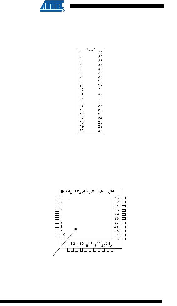
1. Pin Configurations
Figure 1-1. Pinout ATmega32A
|
|
|
|
|
|
PDIP |
||
(XCK/T0) PB0 |
|
|
|
PA0 (ADC0) |
||||
|
|
|
||||||
|
|
|
||||||
(T1) PB1 |
|
|
|
PA1 (ADC1) |
||||
|
|
|
||||||
|
|
|
||||||
(INT2/AIN0) PB2 |
|
|
|
PA2 (ADC2) |
||||
|
|
|
||||||
|
|
|
||||||
(OC0/AIN1) PB3 |
|
|
|
PA3 (ADC3) |
||||
|
|
|
||||||
|
|
|
||||||
|
(SS) |
PB4 |
|
|
|
PA4 (ADC4) |
||
|
|
|
||||||
|
|
|
||||||
(MOSI) PB5 |
|
|
|
PA5 (ADC5) |
||||
|
|
|
||||||
|
|
|
||||||
(MISO) PB6 |
|
|
|
PA6 (ADC6) |
||||
|
|
|
||||||
|
|
|
||||||
(SCK) PB7 |
|
|
|
PA7 (ADC7) |
||||
|
|
|
||||||
|
|
|
||||||
|
|
RESET |
|
|
|
|
AREF |
|
|
|
|
||||||
|
|
|
||||||
|
|
|
VCC |
|
|
|
GND |
|
|
|
|
||||||
|
|
|
||||||
|
|
|
GND |
|
|
|
AVCC |
|
|
|
|
||||||
|
|
XTAL2 |
|
|
|
PC7 (TOSC2) |
||
|
|
|
||||||
|
|
XTAL1 |
|
|
|
PC6 (TOSC1) |
||
|
|
|
||||||
(RXD) PD0 |
|
|
|
PC5 (TDI) |
||||
|
|
|
||||||
(TXD) PD1 |
|
|
|
PC4 (TDO) |
||||
|
|
|
||||||
(INT0) PD2 |
|
|
|
PC3 (TMS) |
||||
|
|
|
||||||
(INT1) PD3 |
|
|
|
PC2 (TCK) |
||||
|
|
|
||||||
(OC1B) PD4 |
|
|
|
PC1 (SDA) |
||||
|
|
|
||||||
(OC1A) PD5 |
|
|
|
PC0 (SCL) |
||||
|
|
|
||||||
(ICP1) PD6 |
|
|
|
PD7 (OC2) |
||||
|
|
|
||||||
TQFP/MLF
(MOSI) PB5 (MISO) PB6 (SCK) PB7 RESET VCC GND XTAL2 XTAL1
(RXD) PD0 (TXD) PD1 (INT0) PD2
Note:
Bottom pad should
be soldered to ground.
|
(SS) |
(AIN1/OC0) |
(AIN0/INT2) |
(T1) |
(XCK/T0) |
GND |
|
|
(ADC0) |
(ADC1) |
(ADC2) |
(ADC3) |
||||||||||
|
|
|
||||||||||||||||||||
|
|
|
||||||||||||||||||||
PB4 |
PB3 |
PB2 |
PB1 |
PB0 |
VCC PA0 |
PA1 |
PA2 |
PA3 |
||||||||||||||
|
|
|
|
|
|
|
|
|
|
|
|
|
|
|
|
|
|
|
|
|
|
|
|
|
|
|
|
|
|
|
|
|
|
|
|
|
|
|
|
|
|
|
|
|
|
PA4 (ADC4)
PA5 (ADC5)
PA6 (ADC6)
PA7 (ADC7)
AREF
GND
AVCC
PC7 (TOSC2)
PC6 (TOSC1)
PC5 (TDI)
PC4 (TDO)
PD3 |
PD4 |
PD5 |
PD6 |
PD7 |
VCC GND |
PC0 |
PC1 |
PC2 |
PC3 |
(INT1) |
(OC1B) |
(OC1A) |
(ICP1) |
(OC2) |
|
(SCL) |
(SDA) |
(TCK) |
(TMS) |
2 ATmega32A
8155B–AVR–07/09