

Figure
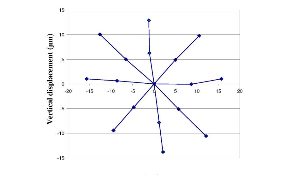
6.9: Primary axes of movements show trajectories along ~45°,
demonstrating that Cartesian control of fiber is possible.Horizontal displacement
 As
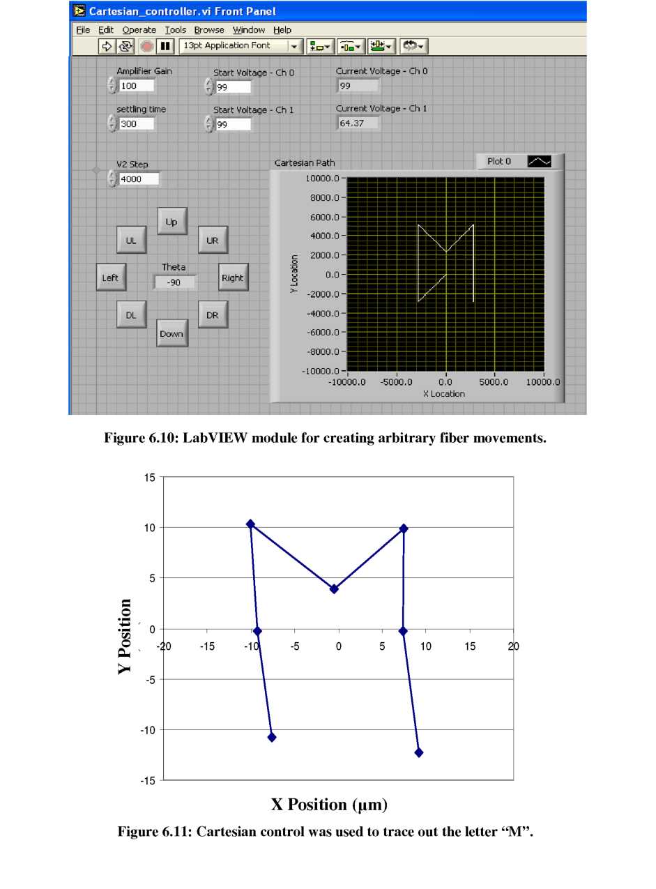
a brief demonstration that the Cartesian control principle produces
similar results starting from an arbitrary point (not the center), a
module was created in LabVIEW to automatically create successive
fiber movements at the behest of an operator. The LabVIEW module
(shown in Figure 6.10) allows the user to define a starting location
and then press buttons to determine the direction and magnitude of
the next fiber movement. While buttons only exist for every 45° in
the figure, arbitrary angles can also be manually entered with
slight changes to the program. To demonstrate this operability, the
letter “M” was traced out with the fiber tip using sequential
movements and facet scans to measure fiber location (see Figure
6.11). Both vertical and angled trajectories across the diamond
alignment area were necessary to create the desired shape. Once
again slight non-linear motion was observed.
As
a brief demonstration that the Cartesian control principle produces
similar results starting from an arbitrary point (not the center), a
module was created in LabVIEW to automatically create successive
fiber movements at the behest of an operator. The LabVIEW module
(shown in Figure 6.10) allows the user to define a starting location
and then press buttons to determine the direction and magnitude of
the next fiber movement. While buttons only exist for every 45° in
the figure, arbitrary angles can also be manually entered with
slight changes to the program. To demonstrate this operability, the
letter “M” was traced out with the fiber tip using sequential
movements and facet scans to measure fiber location (see Figure
6.11). Both vertical and angled trajectories across the diamond
alignment area were necessary to create the desired shape. Once
again slight non-linear motion was observed.
The 45° trajectories and “M” tests have clearly demonstrated that Cartesian control of the fiber tip location can be achieved using simplified geometrical transforms to control the coupled motion of two alignment wedges. Improvements in wedge morphology and angle are expected to improve the symmetry of fiber movement.
Hysteresis Evaluation
Another important quasi-static characteristic to investigate is hysteresis of the