Figure
6.7: Coupled power contours created using the gray-scale fiber
aligner for a fixed target fiber location as voltage combinations
are applied to the device.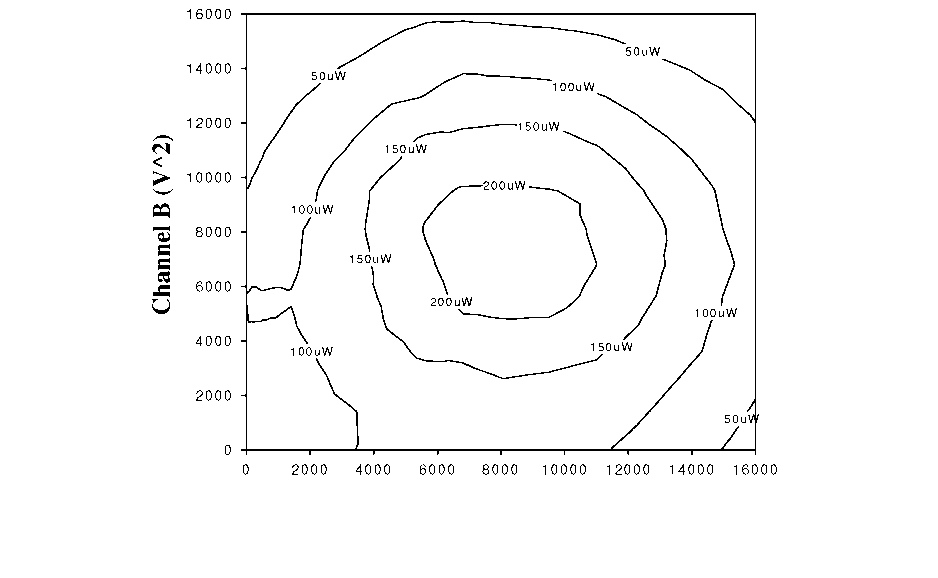
Channel a (va2)
Cartesian Control
As evident from the diamond test, when one wedge is kept stationary and the
other moved, the fiber tip will trace out an angled trajectory parallel to one side of the diamond-shaped alignment area shown in Figure 6.6. This essentially leads to a rotated coordinate system (in V space) where moving one actuator creates fiber movement along a tilted axis. Yet, in some cases it may be advantageous to move the fiber along Cartesian coordinates; for example, to map optical sources with complicated modes.
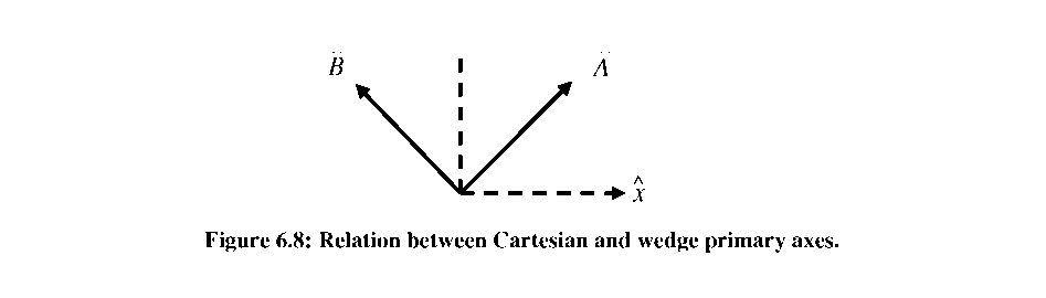 Referring
to Figure 6.8, we see that the Cartesian axes are simply summations
of the angled fiber trajectories caused by individual wedge
movements:
Referring
to Figure 6.8, we see that the Cartesian axes are simply summations
of the angled fiber trajectories caused by individual wedge
movements:
ELECTROSTATIC MEMS ACTUATORS USING GRAY-SCALE TECHNOLOGY 1
Brian Carl Morgan, Doctor of Philosophy, 2006 1
1. Introduction 1
1.1. Introduction 1
1.2. Summary of Thesis Accomplishments 1
1.3. Literature Review 2
1.3.1. 3-D Fabrication Techniques 3
1.3.1.1. Serial Unit Processes 3
1.3.1.2. Batch Fabrication 4
1.3.2. Praditional MEMS Actuators 5
1.3.2.1. Static Actuation 5
1.3.2.2. MEMS Resonators 6
1.3.3.1. Passive Techniques 8
1.3.3.2. Active Techniques 8
1.4. Thesis Objectives and Structure 10
CHAPTER 2: GRAY-SCALE TECHNOLOGY 11
2.1. Introduction 11
2.2.1. Theoretical Background 12
2.2.2. Optical Mask Constraints 14
2.2.3. Standard Lithography Process 16
2.3. Design and Lithography Advancements 16
2.3.1. Minimum Feature Limitations 17
2.3.2. 3-D Profile Control 17
2.3.3. Double Exposures 19
2.4. Pattern Transfer 20
2.4.1. Deep Reactive Ion Etching (DRIE) 21
2.4.2. Selectivity Characterizations 22
2.5. Technology Collaborations 24
2.5.1. Micro-compressor (ARL + MIT) 25
2.5.2. Phase Fresnel Lens (NASA) 27
2.5.3. 3-D Substrates for Packaging (Toshiba) 32
2.6. Conclusion 35
CHAPTER 3: ELECT ROSTATIC COMB-DRIVES USING GOAY-SCALE TECHNOLOGY 36
3.1. Introduction 36
3.2. Electrostatic Actuation Fundamentals 36
3.3. Tailored Comb-finger Design and Simulation 38
3.3.1. Analytical Displacement Simulations (2-D) 39
3.3.2. Finite Element Analysis (3-D) 40
3.3.3. Instability Considerations 43
3.4. Reduced Height Suspensions 45
3.5. Fabrication 46
3.6. Comb-drive Testing 48
3.6.1. Reduced Height Comb-fingers 48
3.6.2. Reduced Height Suspensions 49
3.7. Conclusion 51
CHAPTER 4: VERTICALLY-SHAPED TUMABLE MEMS RESONATORS 51
4.1. Introduction 51
4.2. Tunable MEMS Resonator Operation 52
4.3. Gray-scale Electrostatic Springs 55
4.3.2. Simulation 57
4.3.3. Layout and Fabrication 60
4.4. Testing and Characterization 61
4.4.2. Weakening Resonator Tests 64
4.4.3. Stiffening Resonator Tests 65
4.4.4. Tuning Summary 66
4.5. Non-linear Stiffness Coefficients 68
CHAPTER 5: GR AY-SCALE FIBER ALIGNER I: Conce pt, Design, an d Fabrication 73
5.2. Device Concept 73
5.3. Fiber Coupling Loss Analysis 75
5.4.2. Alignment Wedges 85
5.5. Fabrication 87
5.7. Actuation Concept Demonstration 89
5.8. Conclusion 90
CHAPTER 6: GRAY-SCALE FIBER ALIGNER II: Optical Testing and Characterization 91
6.2.1. Hardware 91
6.2.2. Instrumentation Characterization and Limitations 92
6.3. Static Testing 96
6.3.1. “Diamond” Extents 96
6.3.2. Power Mapping 97
6.3.3. Cartesian Control 97
6.3.4. Hysteresis Evaluation 102
6.5. Automated Fiber Alignment Results 108
6.5.1. Cleaved Fiber - InP Waveguide (Speed) 108
6.5.2. Cleaved Fiber - Lensed Fiber (Resolution) 109
APPENDIX B: Process Flow for Gray-scale SOI process 120
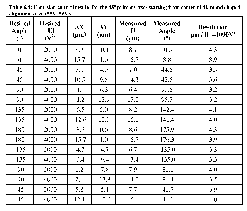
Using these transforms, the fiber tip can be directed in any Cartesian direction
from any starting point within the diamond alignment area. To show this capability, the
22
fiber was actuated along trajectories every 45° for \U\=2000V and \U\=4000V , starting from the middle of the actuator range (99V, 99V). The measured fiber locations after actuation are shown in Table 6.4 and Figure 6.9. For the angled trajectories, one wedge remains stationary while the other wedge slides the fiber up/down the slope. For the vertical and horizontal trajectories, the wedges must move in tandem to produce the desired fiber movement.