

The
most critical components of this fiber actuator are the opposing
sloped
alignment
wedges, since they contact the fiber directly and enable the
out-of-plane
Figure
5.11: Possible alignment area covered (in the X-Y plane of Figure
9) for (a) a planar comb- drive actuator (k=5 N/m, gap=10^m, N=200,
Vmax=90V),
where the displacement resolution varies depending on position, and
(b) a gray-scale tailored force actuator exhibiting improved
resolution at large deflections (k=5 N/m, gap=10^m, N=200,
Vmax=120V).Alignment Wedges
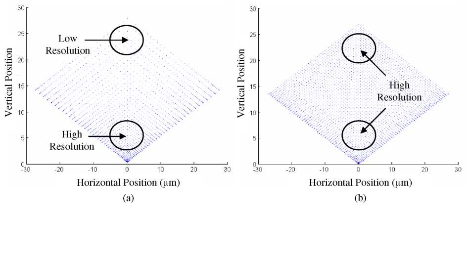 For
the case of 45° alignment wedges and comb-drive actuators, we can
plot the rest position of the fiber as a function of applied
voltage. Figure 5.11(a) shows the possible v-groove alignment area,
where each point represents a case of discrete applied voltages to
comb-drives A and B from Figure 5.3. Taking the point (0,0) as the
initial fiber resting place before actuation, the center of an
optical fiber can be moved to any point within the boundaries of
this imaginary diamond-shaped alignment area. Note that the uneven
spacing of points in Figure 5.11(a) derives from the quadratic
displacement of planar comb-drive actuators, resulting in alignment
resolution that varies with position. Future devices could
incorporate the variable-height gray-scale comb-drives discussed in
Chapter 3 which could improve alignment resolution at large
displacements, as shown in Figure 5.11(b).
For
the case of 45° alignment wedges and comb-drive actuators, we can
plot the rest position of the fiber as a function of applied
voltage. Figure 5.11(a) shows the possible v-groove alignment area,
where each point represents a case of discrete applied voltages to
comb-drives A and B from Figure 5.3. Taking the point (0,0) as the
initial fiber resting place before actuation, the center of an
optical fiber can be moved to any point within the boundaries of
this imaginary diamond-shaped alignment area. Note that the uneven
spacing of points in Figure 5.11(a) derives from the quadratic
displacement of planar comb-drive actuators, resulting in alignment
resolution that varies with position. Future devices could
incorporate the variable-height gray-scale comb-drives discussed in
Chapter 3 which could improve alignment resolution at large
displacements, as shown in Figure 5.11(b).
actuation. Once again, gray-scale technology will be used to integrate the required 3-D silicon wedges with in-plane electrostatic MEMS comb-drives. The primary difficulty when designing the alignment wedges is balancing the wedge angle, ARDE effects (see Section 2.5.2.1), and number of gray levels (i.e. morphology).
The exact angle of the wedges is not critical, but excessively shallow or steep angles could cause slippage or jamming of the fiber. A target angle of approximately 45° was chosen as the initial goal for the wedge design, ideally resulting in similar horizontal and vertical resolution. The alignment wedges are located within the open fiber trench, which is almost an order of magnitude wider than the comb-drive finger spacing (200pm vs. 30pm). This large size difference will lead to significant ARDE between the two structures. To anticipate the over etching required to fully define the comb-drive fingers/spaces, the alignment wedges were designed to have a ~30pm vertical shift (created by introducing a constant offset in the CARDE process discussed in Chapter 2).
The selection of the gray-scale mask pitch and pixel set for defining the alignment wedges is extremely important. Ideally, after fabrication, the sloped wedges should be smooth compared to the size of the optical fiber (diameter=125jum) to enable continuous motion. Yet, considering the mask design limitations discussed in Chapter 2, tall and smooth slopes are a challenge when using a single gray-scale exposure. Compounding this difficulty is the fact that the CARDE offset renders a large number of lower gray levels unusable. Thus, the importance of pitch selection can be seen in the following simulations, based on the Gaussian approximation and pixel limitations discussed earlier in Chapter 2. Two different gray-scale alignment wedge profiles were simulated, both assuming an etch selectivity of 60:1 and a 30pm over-etch (due to ARDE). The first profile, shown in Figure 5.12(a), uses a mask pitch of 2.8pm with only ~25 useable gray levels, resulting in a prominent stair stepped profile. In contrast, Figure 5.12(b) shows a simulated profile using a pitch of 3.2pm, which enables ~50 gray levels within the desired range (pixel sets are given in Appendix E). Given these simulated profiles, the 3.2pm pitch is expected to produce smoother fiber motion, but still has room for improvement. These alignment wedges could be an excellent candidate for the doubleexposure lithography technique introduced in Chapter 2, however it would require significantly more characterization.
