

1. Introduction 1
1.1. Introduction 1
1.2. Summary of Thesis Accomplishments 1
1.3. Literature Review 2
1.3.1. 3-D Fabrication Techniques 3
1.3.1.1. Serial Unit Processes 3
1.3.1.2. Batch Fabrication 4
1.3.2. Praditional MEMS Actuators 5
1.3.2.1. Static Actuation 5
1.3.2.2. MEMS Resonators 6
1.3.3.1. Passive Techniques 8
1.3.3.2. Active Techniques 8
1.4. Thesis Objectives and Structure 10
CHAPTER 2: GRAY-SCALE TECHNOLOGY 11
2.1. Introduction 11
2.2.1. Theoretical Background 12
2.2.2. Optical Mask Constraints 14
2.2.3. Standard Lithography Process 16
2.3. Design and Lithography Advancements 16
2.3.1. Minimum Feature Limitations 17
2.3.2. 3-D Profile Control 17
2.3.3. Double Exposures 19
2.4. Pattern Transfer 20
2.4.1. Deep Reactive Ion Etching (DRIE) 21
2.4.2. Selectivity Characterizations 22
2.5. Technology Collaborations 24
2.5.1. Micro-compressor (ARL + MIT) 25
2.5.2. Phase Fresnel Lens (NASA) 27
2.5.3. 3-D Substrates for Packaging (Toshiba) 32
2.6. Conclusion 35
CHAPTER 3: ELECT ROSTATIC COMB-DRIVES USING GOAY-SCALE TECHNOLOGY 36
3.1. Introduction 36
3.2. Electrostatic Actuation Fundamentals 36
3.3. Tailored Comb-finger Design and Simulation 38
3.3.1. Analytical Displacement Simulations (2-D) 39
3.3.2. Finite Element Analysis (3-D) 40
3.3.3. Instability Considerations 43
3.4. Reduced Height Suspensions 45
3.5. Fabrication 46
3.6. Comb-drive Testing 48
3.6.1. Reduced Height Comb-fingers 48
3.6.2. Reduced Height Suspensions 49
3.7. Conclusion 51
CHAPTER 4: VERTICALLY-SHAPED TUMABLE MEMS RESONATORS 51
4.1. Introduction 51
4.2. Tunable MEMS Resonator Operation 52
4.3. Gray-scale Electrostatic Springs 55
4.3.2. Simulation 57
4.3.3. Layout and Fabrication 60
4.4. Testing and Characterization 61
4.4.2. Weakening Resonator Tests 64
4.4.3. Stiffening Resonator Tests 65
4.4.4. Tuning Summary 66
4.5. Non-linear Stiffness Coefficients 68
CHAPTER 5: GR AY-SCALE FIBER ALIGNER I: Conce pt, Design, an d Fabrication 73
5.2. Device Concept 73
5.3. Fiber Coupling Loss Analysis 75
5.4.2. Alignment Wedges 85
5.5. Fabrication 87
5.7. Actuation Concept Demonstration 89
5.8. Conclusion 90
CHAPTER 6: GRAY-SCALE FIBER ALIGNER II: Optical Testing and Characterization 91
6.2.1. Hardware 91
6.2.2. Instrumentation Characterization and Limitations 92
6.3. Static Testing 96
6.3.1. “Diamond” Extents 96
6.3.2. Power Mapping 97
6.3.3. Cartesian Control 97
6.3.4. Hysteresis Evaluation 104
6.5. Automated Fiber Alignment Results 110
6.5.1. Cleaved Fiber - InP Waveguide (Speed) 110
6.5.2. Cleaved Fiber - Lensed Fiber (Resolution) 111
APPENDIX B: Process Flow for Gray-scale SOI process 122
(d - z)
The major drawbacks of the parallel plate tuning technique are that the electrostatic spring strength depends on the magnitude of vibration of the cantilever and the initial gap (d), which is dependent on the tuning voltage [72]. Thus, the tune and actuation voltages are inherently coupled.
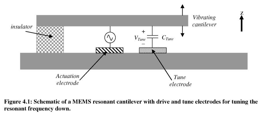

DC voltage can create an electrostatic spring over large displacements. Note that a constant gap and height comb-finger should provide a uniform mechanical force along the travel distance, so electrostatic spring would be observed.
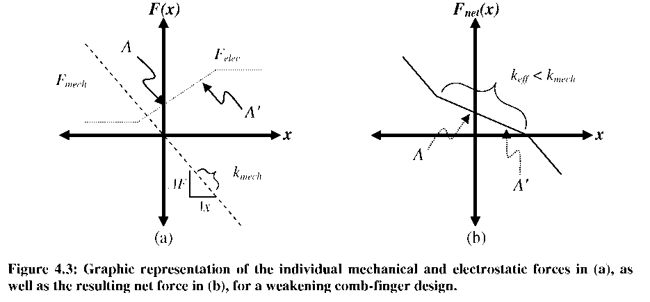
Describing the variable gap situation using the energy method is now slightly less intuitive (but still valid) because both the gap and area of the capacitor change with distance. Instead, we can qualitatively consider the forces generated by the comb-fingers. Applying a voltage (V) to the static electrode of Figure 4.2 creates an electrostatic force in the positive x-direction on the moving finger. As the comb-finger moves from point “A” to point “A',” the electrostatic force remains in the positive x-direction and the magnitude increases, shown schematically in Figure 4.3(a). Also shown in Figure 4.3 is the mechanical restoring force (Fmech) created by the spring (kmech). In a sense, the tuning electrode “helps” pull the resonator in the x-direction more as the engagement increases, weakening the spring (keff< kmech). A plot of the net force (Fnet) in Figure 4.3(b) shows the reduced keff is valid over the range where the gap changes with distance.
While variable gap resonators are versatile, once again their tuning ability comes at the expense of dramatically increasing the device size. However, as shown in Chapter 3, vertically-shaped gray-scale comb-fingers can provide variable force-engagement profiles over large travel ranges without increasing the footprint of a comb-finger pair.