Reduced Height Suspensions
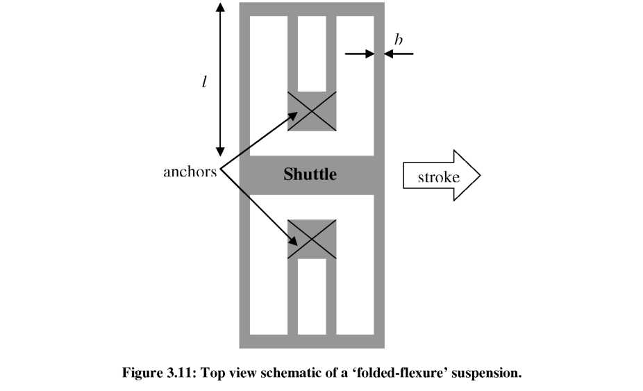
While shaping comb-fingers in the vertical dimension can alter the force generated by the comb-drive, gray-scale technology may also be used to locally reduce the height of comb-drive suspensions, for tailoring spring constants and/or resonant frequencies. Significant research has been performed regarding the various suspension designs possible for electrostatic actuators [50, 52-54, 135]. The ‘folded-flexure’ suspension design, shown schematically in Figure 3.11, is one of the simplest designs and has a relatively high compliance in the direction of the stroke, while providing stability in the direction perpendicular to the stroke (i.e. large Axmax). The approximate spring constant in the direction of motion, kSuspension, of the ‘folded-flexure’ design is [50]:
2Ehb3
k = (47)
Suspension 13 ^ '
where E is Young’s Modulus, h is the spring height, l is the leg length, and b is the width of each leg. For planar designs, the spring constant is usually changed by adjusting the
spring length (at the expense of increased device area), or the spring width (at the expense of higher aspect ratio). However, gray-scale technology offers the possibility of tuning the suspension without increasing device area or aspect ratio.

Fabrication
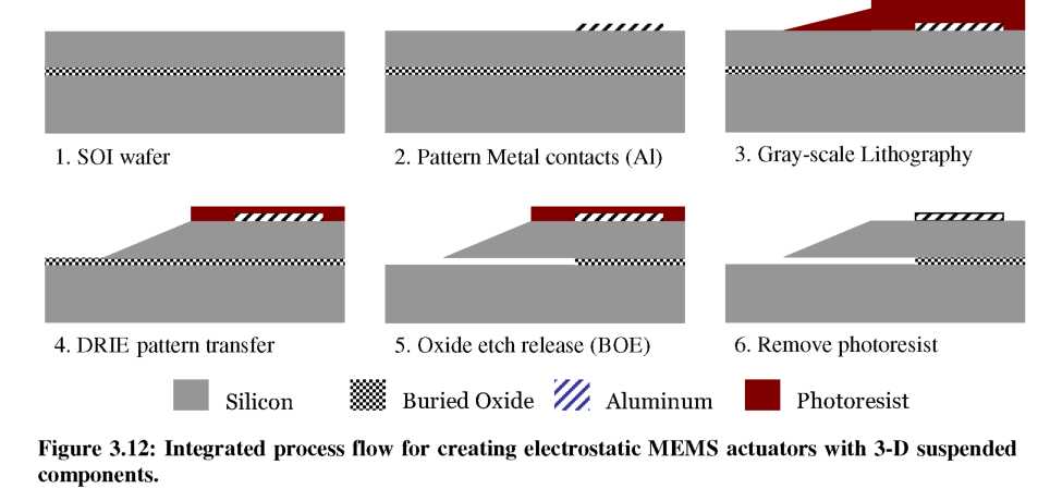
In order to integrate 3-D structures within an electrostatic MEMS actuator, the gray-scale process must be developed as part of an appropriate process flow. The fabrication process developed in this work, and outlined in Figure 3.12, is based on silicon-on-insulator (SOI) technology, where a silicon dioxide sacrificial layer is sandwiched between two crystalline silicon substrates of customized thickness.
Metal liftoff is first used to pattern contact pads and alignment marks. Gray-scale lithography is then performed in a projection lithography system (GCA-Ultratech) at the Laboratory for Physical Sciences (LPS) using a specifically designed gray-scale optical mask. DRIE is used to transfer the planar and variable height structures into the silicon simultaneously. As discussed in Chapter 2, the etch selectivity is controlled to properly define the vertical dimensions of each gray-level in silicon. Before removing the remaining photoresist, the wafer is dipped in buffered hydrofluoric acid (BHF 1:6) to remove the sacrificial silicon dioxide layer. Soaking in successive solutions of isopropyl alcohol (IPA) enables released structures without significant stiction problems due to its lower surface tension. Oxygen plasma is used to strip any remaining photoresist. Explicit process details are given in Appendix B.
The design and fabrication challenges for such devices fall into two main categories: optical mask design and DRIE control. For designing the optical mask, a small offset was introduced between the desired structure edge and the pixilated design, according to the characterization of Section 2.3.1. For variable height comb-fingers, this offset was very important to ensure that the gap between fingers was constant. For DRIE, it was necessary to control the etch selectivity while etching high aspect ratio structures (10:1) and combating aspect ratio dependent etching (ARDE), as discussed previously in Chapter 2 [34]. In the case of variable-height comb-fingers, this means the etch selectivity inside the fingers is different from that in open areas. By using the buried
oxide layer as an etch stop, over-etching of the sample was used to further etch the grayscale structures without significantly affecting adjacent planar structures.
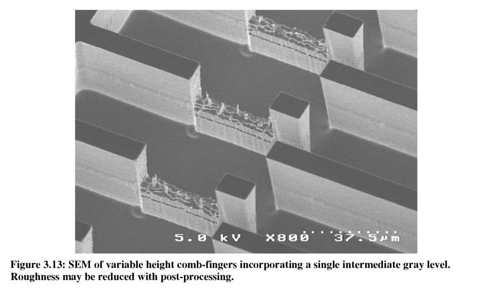
An SEM of the initial variable height comb-finger design after DRIE is shown in Figure 3.13. A single gray-level 30p,m long and 10p,m high was used to remove a ‘notch’ from a planar comb-finger. It is important to note that the roughness seen on the gray level is easily removed with short isotropic plasma etching steps, and as such should have negligible effect on the capacitance and device performance. Figure 3.14 shows an SEM of a different variable height comb-finger design after fabrication and a short isotropic plasma etching step. The roughness is essentially gone, leaving a smooth reduced height surface. An example of a reduced height suspension fabricated with gray-scale technology is shown in Figure 3.15, where roughness is inconsequential for the mechanical properties of the suspension.