Instability Considerations
One
issue that has been ignored to this point is the stability of the
comb-drive actuator. In the analysis presented in Section 3.2, it was
assumed that all forces in the y- direction (perpendicular to the
stroke) will cancel. However, that assumption is premised on the
moving comb-fingers being exactly
У2
way
between the stationary fingers. In reality, the comb-fingers are
always slightly off-center and the force in the y-direction is:
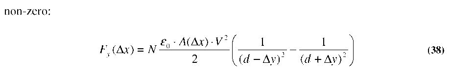
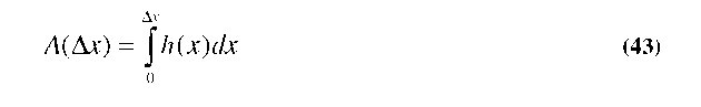
Where
A(Ax)
is the effective overlap area of a parallel plate capacitor on each
side of the moving comb-finger. While A(Ax)
does not explicitly take fringing fields into account, any
capacitance value including fringing fields can be represented as an
equivalent parallel plate case ignoring fringing fields.
We
can now define a virtual spring constant in the y-direction
(ky-virtual)
as the derivative of Fy
with respect to y, evaluated at the Ay=0
(center) position:
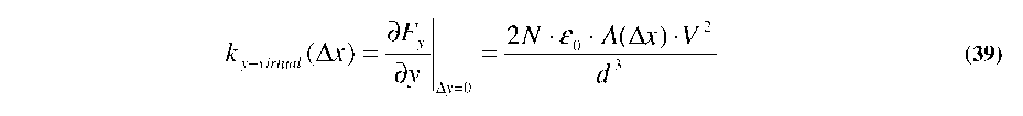
This
spring constant essentially represents the amount of instability
present due to electrostatic forces. When this virtual spring
constant of the electrostatic force exceeds the real mechanical
spring constant of the suspension in the y-direction (ky-real),
an instability point is reached and both sets of comb-fingers will
likely ‘snap’ together. If
we
set ky.virtual
= ky-real,
we can find the maximum stable deflection point (Axmax).
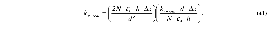
For the case of a traditional, planar comb-drive, we start by
re-arranging Equation 30 to be:

2
Substituting
this V
expression into Equation 39 (set to ky-real),
and using the fact that for the planar case A(x)=h-Ax,
yields:
Collecting
terms and solving for Ax,
we find the maximum stable deflection point for a traditional, planar
comb-drive to be:
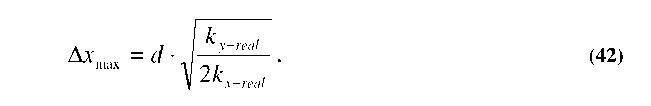
Thus,
the maximum displacement is actually dictated by the ratio of spring
constants in the x- and y-directions, rather than their absolute
value. It should be noted that the spring constants in Equation 42
are real, instantaneous values. While an approximation, Equation 42
can be used as a reasonable guideline for choosing a suspension
design to suit your desired displacement needs. Further discussion on
the design and performance of comb-drive suspensions is provided in
Section 3.4.
For
the case of a gray-scale tailored comb-finger however, Equation 42 is
no longer applicable. Since the height is now a function of
displacement, we must write A(Ax)
as an integral:
Making
Equation 39:

2
Similarly,
Equation 40
no-longer
holds as the V
(x)
relationship is now a complicated function dependent on h(x),
Ax, kx,
N, e0,
and d:
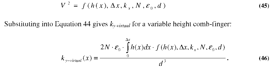
Given
a particular h(x)
profile of the comb-finger, we can solve Equation 46 numerically for
different values of displacement (explicit code is given in Appendix
A). Using the comb-finger profiles and assumptions from Figure 3.5,
ky.virtuai
was calculated as a function of displacement, as shown in Figure
3.10:
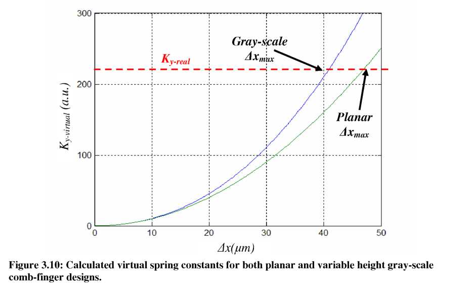
In
Figure 3.10 a fictitious line has been added to represent an
arbitrary value for ky-reai.
It is clear that a device with gray-scale variable height fingers
will reach this limiting threshold earlier than a corresponding
planar device would. Such behavior is expected from the gray-scale
design because improved resolution was obtained by increasing the
voltage required to generate the same displacement. Even though the
overlap area of the gray-scale comb-fingers is smaller than the
planar case, the fact that force scales with V
over-compensates for the reduction in overlap area. Thus, vertically
shaped gray-scale comb-fingers can be expected to have a net decrease
in stability compared to traditional planar comb-drive designs.

