

Finite Element Analysis (3-d)
The glaring difference between the planar and variable height case is the
importance of fringing fields, which are neglected in planar devices. Given the dimensions and aspect ratios involved, simply reducing the height by 50% will not reduce the capacitance at each comb-position by exactly 50%. Thus, our parallel plate model must be extended to include the effects of fringing fields on the capacitance-position profiles to accurately predict actuator behavior using Finite Element Analysis (FEA). During our simulation, limitations imposed by fabrication processes must be considered, as achievable comb-finger gaps and feature aspect ratios will be fabrication dependent. Our analysis and designs will continue to assume 100pm SOI wafers and 10:1 feature aspect ratios, giving an initial gap of d=10^m as done before.
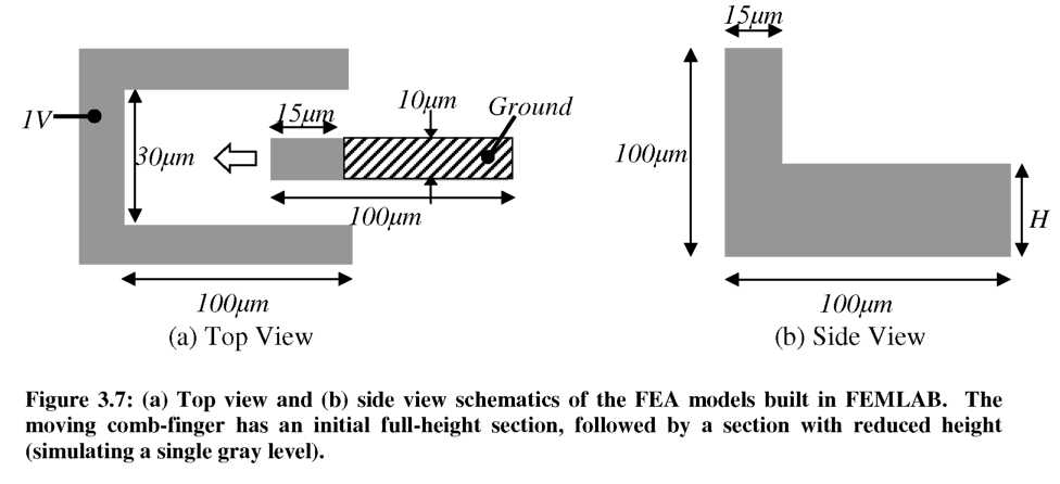
FEA models were constructed in the FEMLAB (V3.0) Electrostatics Module to emulate a grounded, variable height comb-finger moving between two stationary comb- fingers (held at a potential of V=1 Volt). The behavior of a device with N comb-pairs was estimated by multiplication. Top and side view schematics of the basic model geometry simulated are shown in Figure 3.7. While h(x) ^ 1/Ax profiles were discussed earlier for intuition, it will be shown that fringing fields cause a height step to act in a similar manner. All comb-fingers were 100pm long with a maximum height of 100pm. The moving comb-finger has an initial 15 pm full-height section, followed by 85 pm long section with a reduced constant height, H. A ground plane was included 10pm below the comb-fingers to simulate a grounded substrate below the moving fingers. The system was bounded by a 3mm by 3mm grounded box. A mesh containing approximately 200K elements was found to be sufficient to ensure convergence of our solution.
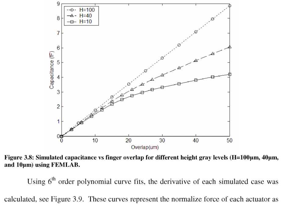
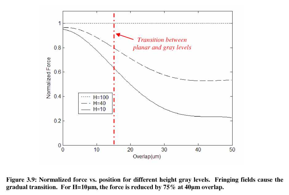
From the FEA simulation results, we see that the effects of fringing fields on the capacitance profile are significant. If a parallel-plate approximation was sufficient for the variable-height case, the normalized force profile would resemble the stepped height profile, h(x), shown in the side view of Figure 3.9. However, the fringing fields and our FEA model are able to “see” the change in height far before the reduced-height section arrives between the stationary fingers at an overlap of 15pm. Consequently, the force profile changes gradually around the transition point, and eventually settles to a smaller constant value. For the case of H=10pm, the total force is reduced by 75%, which should cause a corresponding improvement in displacement resolution of the actuator. Both the
analytical and FEA simulated force profiles will be compared to the experimental results of the fabricated gray-scale actuators in Section 3.6.1.