Conclusion
This chapter has reviewed the research performed on the core gray-scale technology process, an attractive and flexible batch fabrication technique capable of creating variable height structures in silicon using a single lithography and etching step. Developments presented include precise 3-D photoresist profile design techniques, and etch selectivity characterization for controlling the vertical amplification of photoresist profiles into final 3-D silicon structures. Multiple applications were pursued as collaborations on this technology, where the developed techniques were shown to be effective and precise. This research has laid the foundation for gray-scale technology serve as a platform technology for 3-D MEMS actuator development, towards improving device performance and enabling unique actuator behavior.
Chapter 3: elect rostatic comb-drives using goay-scale technology
Introduction
As discussed in previous chapters, the majority of fabrication techniques used in the area of microelectromechanical systems (MEMS) are planar technologies. While myriad MEMS actuators have been developed using these techniques, the design space is severely constricted due to fabrication limitations. Thus, actuator designs must often compromise between desired performance and the ability to be fabricated. In particular, electrostatic MEMS actuators are extremely sensitive to their surrounding geometries, so the ability to design with 3-D structures, can offer a significant performance advantage.
This chapter will review the basic mechanisms at work in electrostatic MEMS comb-drives, as well as highlight the areas where improvements can be made by incorporating 3-D components. Novel methods for tuning comb-drive performance using gray-scale technology in both the comb-fingers and the suspension structure will be discussed. Comb-drive actuators with 3-D comb-fingers and reduced height suspensions are demonstrated that enable customized displacement characteristics and lower driving voltages without increasing device footprint. The integrated process flow and comb- actuators developed here will serve as a building block for the development of tunable resonators (Chapter 4) and optical fiber aligners (Chapters 5 and 6).
Electrostatic Actuation Fundamentals
 Planar
electrostatic actuators, and in particular comb-drives, have been
developed with planar techniques by many groups [46-57]. In order to
properly utilize the capability to now design comb-drives in the
vertical dimension, we will first consider the relevant equations for
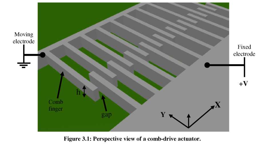
the planar case. Referring to Figure 3.1, two sets of interdigitated
fingers are used to form a parallel plate capacitor. By applying a
potential (V) across the capacitor, an attractive force is generated
between the fingers causing their overlap to increase (assume one set
of comb-fingers to be suspended and the other fixed).
Planar
electrostatic actuators, and in particular comb-drives, have been
developed with planar techniques by many groups [46-57]. In order to
properly utilize the capability to now design comb-drives in the
vertical dimension, we will first consider the relevant equations for
the planar case. Referring to Figure 3.1, two sets of interdigitated
fingers are used to form a parallel plate capacitor. By applying a
potential (V) across the capacitor, an attractive force is generated
between the fingers causing their overlap to increase (assume one set
of comb-fingers to be suspended and the other fixed).
![]() (25)
(25)
where C is the capacitance between the two conductors for a particular position of the suspended fingers. In the voltage constrained case, as one side of the capacitor moves, the electrostatic force involved is the positive spatial derivative of the stored potential energy [131]. Thus, we can write the forces in the x- and y-directions.
Once the comb-fingers are overlapped, the contribution of fringing fields on the derivative of capacitance is essentially negligible [132]. Thus, the capacitance for overlapping section of a single comb-finger is often estimated using a parallel plate approximation:
![]() (28)
(28)
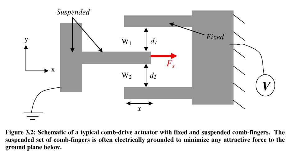
where £0 is the permitivity of vacuum (and approximately that of air), h is the height of the comb-fingers, x is the amount of overlap, and d is the gap between comb-fingers. First considering the force in the y-direction, we see that when the suspended comb- finger is equidistant from both sides (dj=d2), the force generated from each of the capacitors (Cj and C2) will be equal in magnitude, but in opposite direction, canceling each other out. Note that this issue will be revisited later in Section 3.3.3 as it relates to instability of the comb-drive. Using the same assumption (dj=d2), the force in the x- direction can also be calculated as:
![]() (29)
(29)
where N is the number of comb-fingers and V is the applied voltage. For a planar comb- drive where the height of the comb fingers (h) is constant, the derivative of capacitance with respect to position is also constant. Thus, the force generated by a comb-drive is independent of the overlap of the comb-fingers and proportional to the square of the applied voltage.
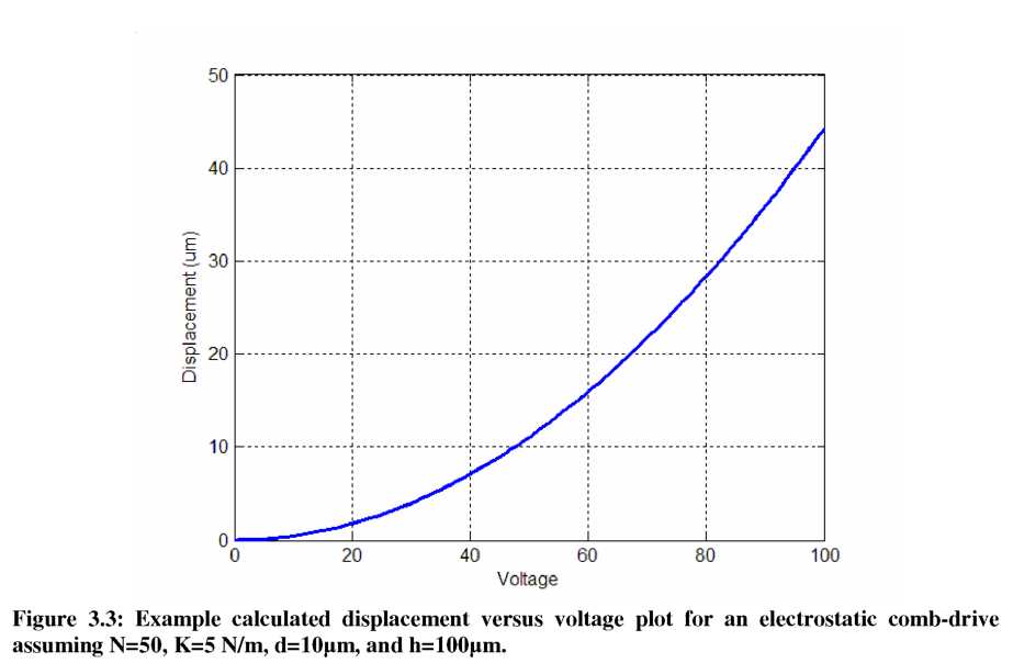
The total displacement of a comb-drive actuator is the point where the generated force and restoring spring force are equal in magnitude. Assuming a linear spring constant (k), the displacement of a planar comb-drive (Jx) is also a quadratic function of applied voltage, V:
Plugging in some example numbers from structures achievable with DRIE, Figure 3.3 shows a plot of the resulting displacement versus voltage curve. A few characteristics of this graph, and comb-drives in general, should be noted: first, displacements >10pm can be easily achieved using <100V, making this an attractive technology for large displacements at the micro-scale. Second, the quadratic relation between displacement and voltage results in large displacements, but at the cost of significantly decreasing resolution at large deflections.