
- •Brian Carl Morgan, Doctor of Philosophy, 2006
- •1. Introduction
- •Introduction
- •Passive Techniques
- •Active Techniques
- •Thesis Objectives and Structure
- •Chapter 2: gray-scale technology
- •Introduction
- •Gray-scale Background
- •Theoretical Background
- •Optical Mask Constraints
- •Standard Lithography Process
- •Design and Lithography Advancements
- •Minimum Feature Limitations
- •2.3.3. Double Exposures
- •Pattern Transfer
- •Deep Reactive Ion Etching (drie)
- •Selectivity Characterizations
- •Technology Collaborations
- •Phase Fresnel Lens (nasa)
- •2.5.2.1. Compensated Aspect Ratio Dependent Etching (carde)
- •Conclusion
- •Chapter 3: elect rostatic comb-drives using goay-scale technology
- •Introduction
- •Electrostatic Actuation Fundamentals
- •Tailored Comb-finger Design and Simulation
- •Analytical Displacement Simulations (2-d)
- •Finite Element Analysis (3-d)
- •Instability Considerations
- •Reduced Height Suspensions
- •Fabrication
- •Comb-drive Testing
- •Reduced Height Comb-fingers
- •Conclusion
- •Introduction
- •Tunable mems Resonator Operation
- •1. Introduction 1
- •1.1. Introduction 1
- •2.1. Introduction 11
- •3.1. Introduction 36
- •4.1. Introduction 51
- •Gray-scale Electrostatic Springs
- •Testing and Characterization
- •Conclusion
- •Introduction
- •Device Concept
- •Figure 5.5: Calculated coupling as two co-axial single-mode fibers are separated longitudinally.
- •Figure 5.6: Alignment schematic for a bent fiber cantilever coupling to a fixed output fiber.
- •Alignment Wedges
- •Fabrication
- •Assembly
- •Actuation Concept Demonstration
- •Introduction
- •Experimental Setup
- •Static Testing
- •Table 6.3: Measured fiber locations for discrete actuation voltages. These 4 points form the corners of a diamond shaped alignment area.
- •Channel a (va2)
- •1. Introduction 1
- •1.1. Introduction 1
- •2.1. Introduction 11
- •3.1. Introduction 36
- •4.1. Introduction 51
- •Horizontal displacement
- •Voltage Squared (v2)
- •Auto-alignment Algorithms
- •Figure 6.16: Simplified hill-climbing algorithm block diagram.
- •Automated Fiber Alignment Results
- •Settling Time, Coarse Threshold Power (%Peak)
- •Testing Summary and Discussion
- •Conclusion
- •Summary of Accomplishments
- •Future Work
Technology Collaborations
The previous sections have discussed the mechanisms behind gray-scale technology, and the steps taken to improve and expand upon its capabilities. Yet these abilities and developments are best understood when discussing specific applications where precisely controlled 3-D silicon structures play a crucial role in overall system/device performance. The following sub-sections briefly describe three technology collaborations, where my research was partnered with outside organizations to develop and demonstrate unique 3-D silicon structures for enhanced performance.
Micro-compressor (ARL + MIT)
Researchers at the U.S. Army Research Laboratory (ARL) and Massachusetts Institute of Technology (MIT) are currently developing a micro turbine engine device, towards portable power generation for the future soldier [108-110]. The development of such a micro-gas turbine engine requires an efficient micro-compressor design that preferably emulates their high efficiency macro-scale counterparts, which are 3-D in nature [111, 112]. While designing 3-D microstructures would not be realistic using traditional micro-fabrication techniques, with the development of gray-scale technology, the design may be driven by optimum performance goals rather than what is achievable with conventional fabrication techniques.
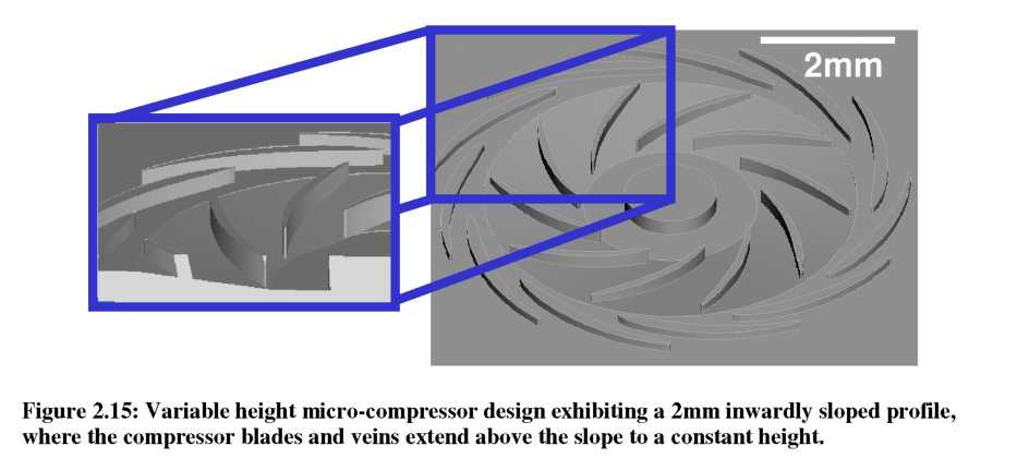
A micro-compressor based on the capabilities of gray-scale technology was recently designed [111, 113], and is shown in Figure 2.15. This improved design has the tops of the blades defined by the original wafer surface, while the bottom of the flow passage is etched to a variable depth. To complete the flow passage, another wafer would be bonded on top for encapsulation. The design calls for the base of the flow passage to slope from 400pm deep at the inner radius to 200pm deep at the outer radius (a 2mm long, 200pm tall slope), resulting in a mass flow inlet to exit ratio of 2:1 in the vertical dimension.
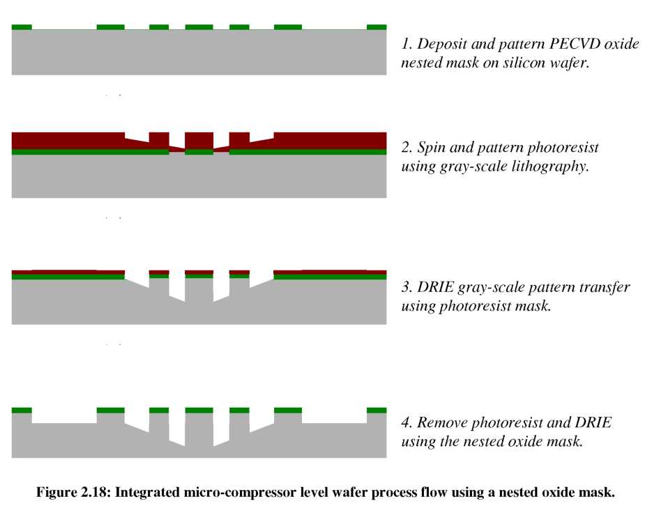
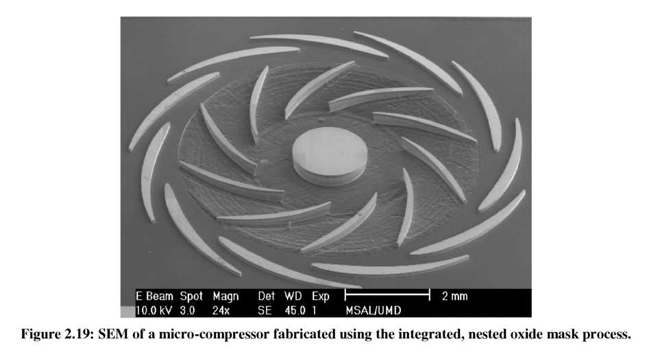
An abbreviated schematic of this process flow is shown in Figure 2.18, while Figure 2.19 is an SEM of the final variable height silicon micro-compressor with smooth outer flow channels.