41.The theory of an ideal propeller (momentum theory of propulsion).
This theory applies to propulsive systems of Class I. In this class, work is done on air from the atmosphere and its energy increased. This increase in energy is used to increase the rearwards momentum of the air, the reaction to which appears as a thrust on the engine or airscrew.
T=pSVo(V,- V)
The thrust can also be calculated from the pressures on the two sides of the disc as T = S(p2 -PI)

This is the ideal propulsive efficiency or the Froude efficiency of the propulsive system.

Using the quite simple momentum theory, we can already deduct important information about the performance of propellers. We can study the influence of the propeller diameter on efficiency as well as how it depends on flight speed or the density of the air (corresponding to a certain altitude). We learn, that an efficient propeller should have a small power loading per disk area, i.e. a large diameter is required.
The momentum theory does neither take the planform of the blade into account nor the characteristics of the airfoil sections. For the design or the analysis of a propeller more sophisticated models are necessary, but the momentum theory always gives a good estimate for the maximum efficiency which we can expect.
It is possible to extend the momentum theory to include rotational losses, which results in an additional efficiency loss of 2 to 5 percent for typical propellers. These losses depend on the velocity of rotation and favor low torque, high rpm conditions.
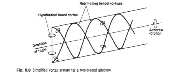
43.Vortex models of a propeller.
An airscrew blade is a form of lifting aerofoil, and as such may be replaced by a hypothetical bound vortex. In addition, a trailing vortex is shed from the tip of each blade. Since the tip traces out a helix as the airscrew advances and rotates, the trailing vortex will itself be of helical form.
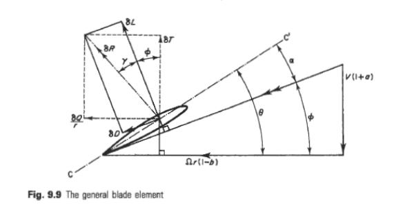
42.The theory of the isolated unit of a blade of a propeller.
If the line CC’ represents the zero-lift line of the blade section then t9 is, by definition, the geometric helix angle of the element, related to the geometric pitch, and a is the absolute angle of incidence of the section. The element will therefore experience lift and drag forces, respectively perpendicular and parallel to the relative velocity VR, appropriate to the absolute incidence a. The values of CL and CD will be those for a two-dimensional aerofoil of the appropriate section at absolute incidence a, since three-dimensional effects have been allowed for in the rotational interference term, bR. This lift and drag may be resolved into components of thrust and ‘torque-force.