

1.3 Polarization by Selective Absorption
Waves emitted by a radio transmitter are usually linearly polarized. The vertical antennas that are used for radio broadcasting emit waves that, in a horizontal plane around the antenna, are polarized in the vertical direction (parallel to the antenna).
The situation is different for visible light. Light from incandescent light bulbs and fluorescent light fixtures is not polarized. The “antennas” that radiate light waves are the molecules that make up the sources. The waves emitted by any one molecule may be linearly polarized, like those from a radio antenna. But any actual light source contains a tremendous number of molecules with random orientations, so the emitted light is a random mixture of waves linearly polarized in all possible transverse directions. Such light is called unpolarized light or natural light. To create polarized light from unpolarized natural light requires a filter.
|
In 1938, E. H. Land (1909–1991) discovered a material, which he called polaroid, that polarizes light through selective absorption by oriented molecules. This material have dichroism, a selective absorption in which one of the polarized components is absorbed much more strongly than the other (Fig. 3.5) is fabricated in thin sheets of long-chain hydrocarbons. The sheets are stretched during manufacture so that the long-chain molecules align. After a sheet is dipped into a solution containing iodine, the molecules become good electrical conductors. However, conduction takes place primarily along the hydrocarbon chains because electrons can move easily only along the chains. |
 Figure
3.5. A Polaroid filter is illuminated by unpolarized natural
light. The transmitted light is linearly polarized along the
polarizing axis.
Figure
3.5. A Polaroid filter is illuminated by unpolarized natural
light. The transmitted light is linearly polarized along the
polarizing axis.As a result, the molecules readily absorb light whose electric field vector is parallel to their length and allow light through whose electric field vector is perpendicular to their length. It is common to refer to the direction perpendicular to the molecular chains as the transmission axis. Polaroid widely used for sunglasses and polarizing filters for camera lenses. A Polaroid filter transmits 80% or more of the intensity of a wave that is polarized parallel to a certain axis in the material, called the polarizing axis, but only 1% or less for waves that are polarized perpendicular to this axis.
1.4 Malus’s law
An ideal polarizing filter (polarizer) passes 100% of the incident light that is polarized parallel to the filter’s polarizing axis but completely blocks all light that is polarized perpendicular to this axis. Such a device is an unattainable idealization. We will assume that all polarizing filters are ideal. In Fig. 3.6 unpolarized light is incident on a flat polarizing filter. Only the component of parallel to the polarizing axis is transmitted. Hence the light emerging from the polarizer is linearly polarized parallel to the polarizing axis.
When unpolarized light is incident on an ideal polarizer as in Fig. 3.6, the intensity of the transmitted light is exactly half that of the incident unpolarized light, no matter how the polarizing axis is oriented:
I0 = ½ Inat (3.5)
I0 – intensity of the polarized light is transmitted through the polarizer,
Inat – intensity of unpolarized light is incident on an polarizer.
We can
resolve the field of the incident wave into a component parallel to
the polarizing axis and a component perpendicular to it. Because the
incident light is a random mixture of all states of polarization,
these two components are, on average, equal. The ideal polarizer
transmits only the component that is parallel to the polarizing axis,
so half the incident intensity is transmitted.


Figure 3.6. Two polarizing sheets whose transmission axes make an angle with each other. Only a fraction of the polarized light incident on the analyzer is transmitted through it.
Figure 3.6 represents an unpolarized light beam incident on a first polarizing sheet, called the polarizer. Because the transmission axis is oriented vertically in the figure, the light transmitted through this sheet is polarized vertically. A second polarizing sheet, called the analyzer, intercepts the beam. In Figure 3.6, the analyzer transmission axis is set at an angle θ to the polarizer axis. We call the electric field vector of the first transmitted beam E0. The component of E0 perpendicular to the analyzer axis is completely absorbed. The component of E0 parallel to the analyzer axis, which is allowed through by the analyzer, is E0cosθ. Because the intensity of the transmitted beam varies as the square of its magnitude, we conclude that the intensity of the (polarized) beam transmitted through the analyzer varies as:
I = I0·cos2θ (3.6).
where I0 is the intensity of the polarized beam incident on the analyzer,
θ - the angle between the optical axes of the polarizer and the analyzer.
Thus, the intensity of the polarized light transmitted through the polarizer and the analyzer:
I = ½ Inat·cos2θ (3.7)
These expression, known as Malus’s law, applies to any two polarizing materials whose transmission axes are at an angle θ to each other. From this expression, we see that the intensity of the transmitted beam is maximum when the transmission axes are parallel (θ =0 or 180°) and that it is zero (complete absorption by the analyzer) when the transmission axes are perpendicular to each other.
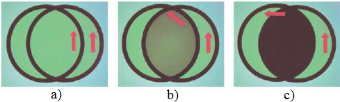
Figure 3.7. The intensity of light transmitted through two polarizers depends on the relative orientation of their transmission axes. (a) The transmitted light has maximum intensity when the transmission axes are aligned with each other. (b) The transmitted light has lesser intensity when the transmission axes are at an angle of 45° with each other. (c) The transmitted light intensity is a minimum when the transmission axes are perpendicular to each other.