- •Institute of higher education
- •Abstract
- •Contents
- •List of the conditional indication and reduction
- •Introduction
- •1 The calculation of baSic electrical quantities
- •2 The calculation of base scales of transformer
- •3 Choice of the designing and calculation of windings
- •4 Definitions of the characteristics of short circuit
- •Figure 4.2 – Distribution of compressing forces for our case
- •5 Calculation of transformer magnetis system
- •6 Thermal computatuion of the transformer
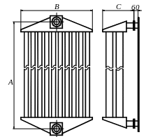
- •Figure 6.2 – Pipes radiator with direct pipes
- •7 Definition of weight of constructional materials and oil of the transformer
- •8 The summary data of account of the transformer
- •Conclusion
- •Tpansformer
- •The list of the literature
- •Appendix а The list of the remarks to course work
6 Thermal computatuion of the transformer
6.1 Thermal computation of the windings
6.1.1 Internal difference of temperature in LV winding for rectangular winding from aluminum wire:
λiz = 0.17 Wt/(m·оС) – thermal conductivity of insulation (by tabl. 9.1, р. 424 [1]);
δ = δiz/2 = 0.0005/2 = 0.00025 – thickness of insulation on one side, m.
Θ01=q1 . δ/ λiz
Θ01 = 972.314. 0.00025/0.17 = 1.43 оС
6.1.2 Difference of temperature on surface of LV winding:
ΘО.М1
= 0.285·![]() = 0.285·972.3140.6
= 17.682 оС.
= 0.285·972.3140.6
= 17.682 оС.
6.1.3 Average excess of temperature of LV winding under temperature of oil:
ΘМ.СР1 = ΘO1 + ΘО.М1 = 1.43 + 17.682 = 19.112 оС.
6.1.4 Internal difference of temperature in HV winding (for rectangular winding from aluminum lead):
ΘО2
=
![]() ,
,
Where р
=
 ,
,
К´Р = 2.71 – for aluminum lead;
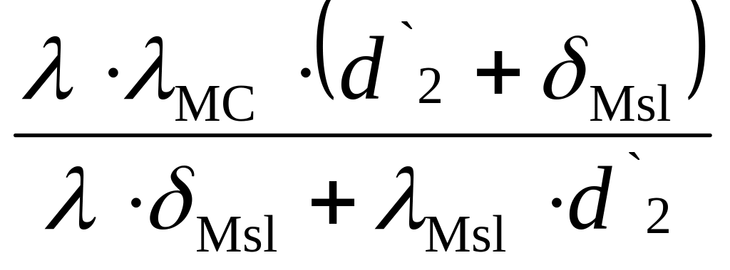
λСР
=
 ,
,
Where λ
=
 =
=
 = 0.629
δМsl = 0.48 mm – thickness of interlayer isolation.
λСР
=
![]() = 0.484
= 0.484
р =
![]() =70890.704 Wt/m3.
=70890.704 Wt/m3.
ΘО2
=
![]() = 8.207 оС.
= 8.207 оС.
6.1.5 Average difference of temperature of HV winding under temperature of oil:
ΘОМ2
= 0.285·![]() = 0.285·589.8490.6
= 13.101 оС.
= 0.285·589.8490.6
= 13.101 оС.
6.1.6 Difference of temperature under surface of HV winding:
ΘОМСР2 = ΘО2 + ΘОМ2 = 8.207 + 13.101 = 21.308 оС.
6.1.7 Allowable excess of temperature of oil above air:
ΘМv = 65 - ΘОМСР1 = 65 –19.186 = 45.814 оС.
6.1.8 Allowable excess of temperature tank’s wall above air:
Θbv = ΘМv – ΘМδ = 45.814 – 5 = 40.814 оС,
Where ΘМδ = 5 оС.
6.1.9 Temperature of oil upper layers:
ΘМbv = 1.2· Θbv = 1.2·40.814 = 48.977 оС < 55 оС.
Figure 6.1 – Basic sizes of tank
6 .2
Thermal calculation of tank design of
the transformer is chosen by taking into account power of the
transformer (table. 9.4, р. 429 [1], I choose a tank with hanging
radiators with oil cooling of windings. Definition of insulation
intervals from lead-ins of HV and LV windings and wall of the tank is
made on figure 6.1.
S1 = 22 mm – insulation interval from lead-in of HV winding to HV winding (table. 4.11, р. 199 [1]).
S2 = S1 =22 mm– insulation interval from lead-in of HV winding to wall of the tank (tabl. 4.11, р. 199 [1]).
d1 = 20 mm – diameter of insulation S = 250 kVA < 10000 kVA.
S3 = 25 mm – insulation interval from lead-in of LV winding to LV winding (tabl. 4.12, р. 201 [1]). D´´2=323
S4 = 22 mm – insulation interval from lead-in of LV winding to wall of the tank (tabl. 4.11, р. 199 [1]).
d2 = 20 mm – diameter of isolation lead-in of HV winding is equal d1.
6.2.1 Minimal width of tank:
B = D´´2 + (S1 + S2 + d1 + S3 + S4 + d2)·10-3
B = 0.283 + (22 + 22 + 20 + 25 + 24 + 20)·10-3 = 0.414 m.
6.2.2 Minimal length of a tank:
А = 2·С + D´´2 + 2·S5·10-3 = 2·0.293 + 0.283 + 2·67·10-3 = 1.174m,
where S5 = S3 + S4 + d2 = 67 mm – interval from external surface of winding to wall of the tank ( fig. 6.1).
6.2.3 Height of an active part of the transformer:
H`а,p = Lleg + 2·hyoke + n·10-3 = 0.545 + 2·0.155 + 40·10-3 = 0.975 m,
where n = 40 mm – thickness of a lining under bottom yoke.
6.2.4 Total depth of a tank:
Нyokee = 300·10-3 m (tabl.9.5, p.431[1] )
Нb = Нa,p. + Нyokee. = 0.895 + 300·10-3 = 0.895 m.
The tank with hanging radiators.
6.2.5 At the tabl. 9.9, р. 442 [1] is chosen tube radiator with two lines of direct pipes with interval between axes of flanges AP = 900 mm, with pipe’s surface ПТР = 2.135 m2 and surface of collectors ПКК = 0.34м2. This radiator is shown on fig. 6.2.
Hanging radiators with direct pipes by natural movement of cooling air use in large diapason of transformer power – from 100 to 6300 kVA Direct pipes are welded by the ends in lower and upper collectors of radiator (fig. 6.2). Sizes В and С of radiator with two lines of pipes is equal 505 and 253 mm.
 The
depth of a tank for installation of these radiators should be:
