- •Task 1. Analysis of stepped rod in tension-compression
- •Task 2. Determination of geometrical characteristics of plane sections
- •Task 3. Construction shear force and bending moment diagrams for beams
- •Full check of strength of the beam by principal stresses
- •Task 5. Torsion computations
- •Task 6. Torsion with bending
- •7. Using the condition of strength determine the necessary diameter
- •Task 2. Determination of displacements in the beam
- •Literature
Task 1. Analysis of stepped rod in tension-compression
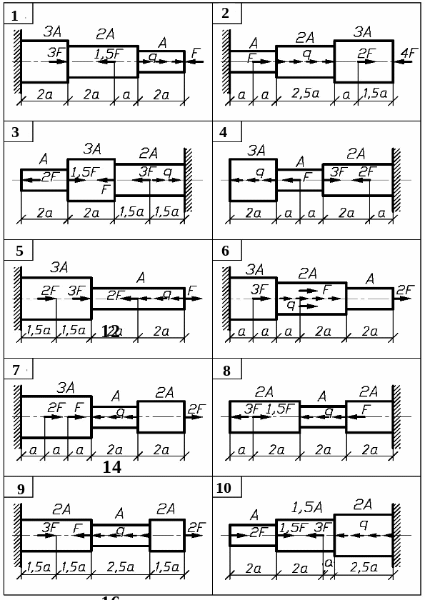
The stepped rod (fig. 1) is under the action of longitudinal axial forces F and distributed load q. To carry out the analysis of the rod.
Take the data for computation from table 1 and material mark from table 2. accept the safety factor as following:
- for ductile materials ny = 1,5; for brittle materials ns = 2,5
Order of work
1. Using the method of the section determine the normal axial force N and normal stress at each section of the rod and draw diagram N and to scale.
2. Determine the absolute elongation l of each section and draw the diagram of the cross-section motion along the rod.
3. Calculate allowable values of stress, determine the dangerous section of the rod and make the conclusion about strength of the rod.
Table 1
variant number / group No. / |
Loading |
Length a , m |
Area A, cm 2 |
|
F, kN |
q , kN/м |
|||
201 |
20 |
12 |
0.4 |
3.0 |
202 |
22 |
10 |
0.5 |
3.5 |
203 |
24 |
16 |
0.6 |
4.0 |
204 |
26 |
14 |
0.7 |
4.5 |
205 |
28 |
20 |
0.8 |
5.0 |
206 |
21 |
11 |
0.9 |
3.5 |
207 |
23 |
15 |
0.35 |
4.5 |
208 |
25 |
13 |
0.45 |
5.0 |
209 |
27 |
19 |
0.55 |
6.0 |
210 |
29 |
17 |
0.65 |
5.5 |
Table 2
variant number |
1 |
2 |
3 |
4 |
5 |
6 |
7 |
8 |
9 |
10 |
Material |
30ХГСА |
45Х |
Ст 3 |
30Г |
Д6 |
СЧ38-60 |
20Х |
12ХН3А |
Д1П |
20Г |

Fig.1. (see also p.5)

Fig.1. Continued (see also p.6)

Fig.1. Ending
Task 2. Determination of geometrical characteristics of plane sections
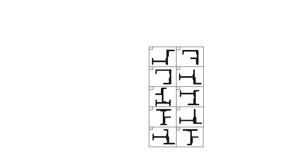
Determine values of the principal centroidal moments of inertia and position of the principal centroidal axes of compound section (fig. 4).
Take the data necessary for computation from table 4.
Order of work
1. Draw the section to scale and mark the dimensions; h – I-siction height, h1 - height of channel, b - width, t - thickness of the stripe.
2. Determine the centroid of the section with respect to selected auxiliary axes. Draw centroidal axes.
3. Determine values of moments of inertia: axial moment Ix and Iy , and product of inertia (centrifugal moment)Ixy respecting central axes.
4. Determine the position of principal centroidal axes of inertia u and v and show them on the sectional drawing.
5. Determine values of the principal moments of inertia Iu and Iv.
6. Make necessary checks for Iyc + Izc = Iu + Iv; Iuv = 0.
table 4
variant number /group No./ |
I-section number, h |
Stripe bt, mm |
Channel number, h1 |
Equal angle, mm |
201 |
10 |
1006 |
16 |
50503 |
202 |
12 |
1206 |
16 |
50504 |
203 |
14 |
1406 |
18 |
50505 |
204 |
16 |
1606 |
18 |
45455 |
205 |
18 |
1806 |
20 |
56564 |
206 |
12 |
2006 |
20 |
56565 |
207 |
14 |
2206 |
22 |
70705 |
208 |
16 |
2406 |
22 |
70706 |
209 |
20 |
1808 |
24 |
56564 |
210 |
18 |
2008 |
24 |
56565 |


Fig.4. (see also p.14)

F ig.4.
Continued (see
also p.15)

F ig.4.
Ending
