Introduction
Welcome to Visual C++. Over the next 21 days, you will learn how to use the features that Microsoft has built into its C++ development environment to enable you to create very advanced applications for the Windows and NT platforms. When Microsoft’s developers first came up with the idea behind Visual C++, they decided to take their worldclass C++ compiler and create a development environment and set of tools that would enable developers to create Windows applications with a level of ease and speed that was unheard of among C++ development environments. Since that first version, Microsoft has continued to improve the tools that are a part of Visual C++ to make it even easier to create Windows applications. As Microsoft has introduced new technologies into the Windows platforms, it has also introduced tools into the Visual C++ suite to make it easy to integrate these new technologies into your applications.
If you are new to C++, don’t worry. I’ve tried to make it easy for you to learn the C++ programming language while also learning how to build applications using the Visual C++ tools. Just in case you find yourself having trouble understanding some aspect of C++, I’ve included a brief overview of the programming language in Appendix A, “C++ Review.”
If you’ve looked at previous versions of this book, you might notice that I’ve completely rewritten the entire book. Our goal with this new version is not just to introduce you to and guide you through the various tools and resources that you will use to build applications with Visual C++; I’ve also tried to include a great deal more detail about the various options that are available to you with each of the features that are covered. This way, you’ll be able to get a lot of use out of this book long after the initial 21 days.
How This Book Is Organized
This book is organized in weeks, with each set of seven days set off into a part unto itself. However, even though the book is organized in weeks, the topics are not neces-sar- ily organized that way.
For the first week, you’ll be covering the basics of building applications with Visual C++. You’ll learn how to use designers to design your application windows. You’ll learn how to use various controls available to you as a Windows application developer. You’ll also learn a lot about the Visual C++ development environment and the tools that it makes available to you.

2 |
Sams Teach Yourself Visual C++ 6 in 21 Days |
By the time you begin the second week, you’ll be doing more and more programming, as the topics become more involved. You’ll still be using the Visual C++ tools to construct your applications, but the programming code will be getting a little more involved. You’ll also start learning about more advanced topics, such as displaying graphics and creating SDI and MDI applications. Toward the end of the second week, you’ll begin to work with databases. This topic spills over into the third and final week.
In the third week, you’ll learn how to create your own modules, DLLs, and ActiveX controls. You’ll also learn how to build multitasking applications, which perform multiple tasks at a time. Finally, you’ll learn how to integrate Microsoft Internet Explorer, and the ActiveX controls it provides, into your applications so that you can extend your applications over the Internet.
After you finish the third week, you’ll be ready to tackle the world of Windows programming with Visual C++. You’ll have the skills and know-how required to build most Windows applications available today.
Conventions Used in This Book
While you are reading this book, you will probably notice a couple conventions that have been used to make it easier for you to learn the topic being discussed.
All the source code in this book is provided in a monospaced font, as shown in Listing 0.1. This includes all the source code from the applications that you will be building and illustrations of how various functions can be used. Whenever you are adding new code, or changing code in a function with other code already there, the line numbers of the code that you add or change will be pointed out in the text.
LISTING 0.1. SOME SAMPLE CODE.
1:void main()
2:{
3:// if you are adding or changing code in an existing
4:// code snippet, I will point out the line numbers in the text.
5:}
If a topic needs special attention, it will be set apart from the rest of the text by one of several special markers:
●Notes
●Tips
●Cautions
Introduction |
3 |
Note
Tip
Caution
Notes offer a deeper explanation of a topic or explain interesting or important points.
Tips are pieces of information that can make things easier.
Cautions warn you about traps that you will want to avoid.
At the end of each day, you’ll find a short quiz and one or two exercises to help make sure that you learned the topic you were studying. Don’t worry—just in case you need the answers to the quizzes and some guidance when building the exercises, the solutions are provided in Appendix B, “Answers.”
Enough said! You didn’t buy this book to read about this book. You bought this book to learn how to use Visual C++ to build Windows applications. So go ahead and flip the page and get started programming…

WEEK 1
At a Glance
Welcome to the world of Visual C++. Over the next three weeks, you’ll learn how to build a wide variety of applications using this extremely flexible and complete programming tool. Each day you’ll learn about a different area of functionality and how you can use it in your applications. What’s more—every one of the areas of functionality will be accompanied with a hands-on sample application that you will build yourself. There’s not a more effective way of learning new technologies than to work with them yourself. Learning by doing…that’s what you’ll do as you make your way through this book.
Over the course of the first week, you’ll learn about several of the basics that are involved in building applications with Visual C++. This starts on the first day as you learn about and become familiar with the Visual C++ development environment by building a simple application.
On Day 2, you’ll begin learning more about the specifics of building applications in Visual C++. You’ll learn about the standard controls that are used in Windows applications, how you can place and configure these on an application window, and how you can interact with them.
On Day 3, you’ll learn how you can capture mouse and keyboard events and react to them in your applications. You’ll see how you can determine where the mouse is in your application space. You’ll also learn how to determine what keys the user is pressing on the keyboard and how you can react to these user actions.
1
2
3
4
5
6
7

6 |
Week 1 |
On Day 4, you’ll learn how to work with timers in a Visual C++ application. You’ll learn how to have two or more timers running at the same time and how you can tell them apart.
On Day 5, you’ll see how you can add additional windows to your application and how you can use them to get information from the user. You’ll see how you can use built-in dialogs to ask the user simple questions and how you can build your own custom dialogs to get more detailed information.
On Day 6, you’ll learn how to create menus to add to your application. You’ll see how you can call functions in your application from menus that you have added to your application.
On Day 7, you’ll learn about the font infrastructure in Windows and how you can access it in your Visual C++ applications. You’ll see how you can build a list of available fonts and how you can display text in any of these fonts.
That will end the first week of this book. At that time, you can look back over what you have learned during the week and think about all that you can do with what you have learned when you build applications. So, without further ado, go ahead and jump in and get started.

WEEK 1
DAY 1
The Visual C++
Development
Environment—Building
Your First Visual C++
Application
Welcome to Sams Teach Yourself Visual C++ 6 in 21 Days. Over the next three weeks, you will learn how to build a wide variety of applications with Microsoft’s Visual C++. What’s even better is that you will learn how to create these types of applications by actually building them yourself. As you read this book, you will be gaining actual programming experience using Visual C++. So let’s get started!
Today, your focus will be on learning about the Visual C++ development environment and some of the tools that it provides for building applications. Although Visual C++ provides more tools than you would probably use in any

8 |
Day 1 |
one application development effort—even more than you could possibly learn to use in a single day—I limit the focus to the primary tools that you will use throughout this book, as well as in just about every application you build with Visual C++. Today, you’ll learn about the following:
•The primary areas of the Visual C++ development environment
•The Application Wizard—how you can use it to build the basic infrastructure for your applications
•The Dialog Painter—how you can use it to paint dialog windows, much in the same way that you can build windows with Visual Basic, PowerBuilder, or Delphi
•The Class Wizard—how you can use it to attach functionality to your application windows
The Visual C++ Development Environment
Before you begin your quick tour around the Visual C++ development environment, you should start Visual C++ on your computer so that you can see firsthand how each of the areas are arranged and how you can change and alter that arrangement yourself.
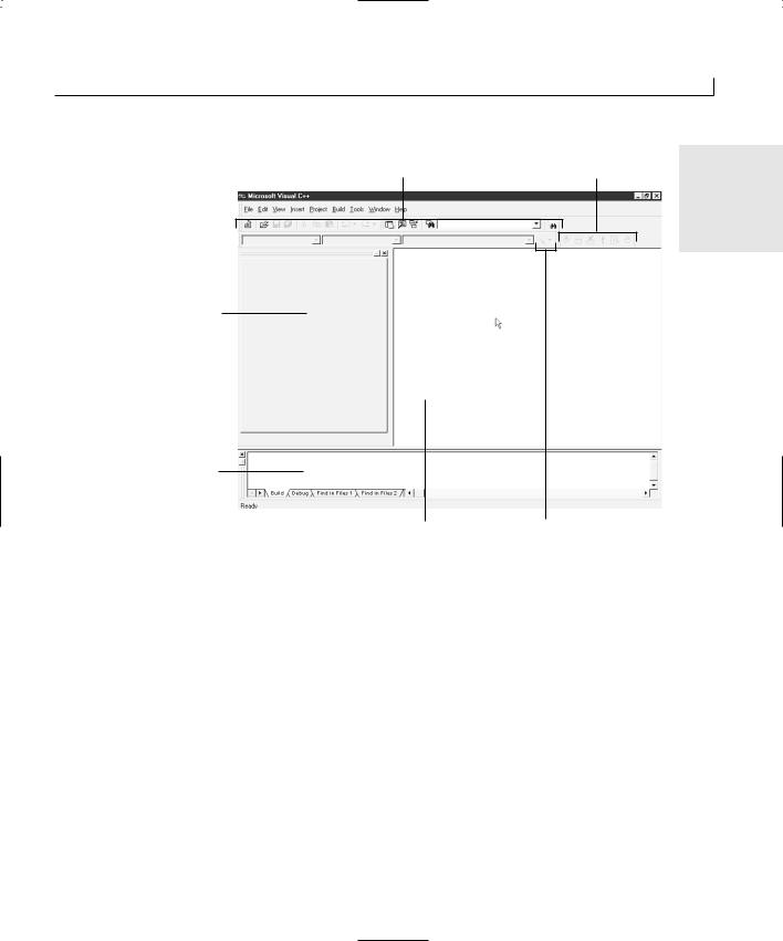
After Developer Studio (the Microsoft Visual development environment) starts, you see a window that looks like Figure 1.1. Each of the areas has a specific purpose in the Developer Studio environment. You can rearrange these areas to customize the Developer Studio environment so that it suits your particular development needs.
The Workspace
When you start Visual C++ for the first time, an area on the left side of Developer Studio looks like it is taking up a lot of real estate and providing little to show for it. This area is known as the workspace, and it is your key to navigating the various pieces and parts of your development projects. The workspace allows you to view the parts of your application in three different ways:
•Class View allows you to navigate and manipulate your source code on a C++ class level.
•Resource View allows you to find and edit each of the various resources in your application, including dialog window designs, icons, and menus.
•File View allows you to view and navigate all the files that make up your application.
Building Your First Visual C++ Application |
9 |
Standard toolbar |
Build minibar |
1 |
|
|
FIGURE 1.1.
The Visual C++ opening screen.
Workspace pane
Output pane
Editor area |
Wizard toolbar |
The Output Pane
The Output pane might not be visible when you start Visual C++ for the first time. After you compile your first application, it appears at the bottom of the Developer Studio environment and remains open until you choose to close it. The Output pane is where Developer Studio provides any information that it needs to give you; where you see all the compiler progress statements, warnings, and error messages; and where the Visual C++ debugger displays all the variables with their current values as you step through your code. After you close the Output pane, it reopens itself when Visual C++ has any message that it needs to display for you.
The Editor Area
The area on the right side of the Developer Studio environment is the editor area. This is the area where you perform all your editing when using Visual C++, where the code editor windows display when you edit C++ source code, and where the window painter displays when you design a dialog box. The editor area is even where the icon painter displays when you design the icons for use in your applications. The editor area is basically the entire Developer Studio area that is not otherwise occupied by panes, menus, or toolbars.
10 |
Day 1 |
Menu Bars
The first time you run Visual C++, three toolbars display just below the menu bar. Many other toolbars are available in Visual C++, and you can customize and create your own toolbars to accommodate how you best work. The three toolbars that are initially open are the following:
•The Standard toolbar contains most of the standard tools for opening and saving files, cutting, copying, pasting, and a variety of other commands that you are likely to find useful.
•The WizardBar toolbar enables you to perform a number of Class Wizard actions without opening the Class Wizard.
•The Build minibar provides you with the build and run commands that you are most likely to use as you develop and test your applications. The full Build toolbar also lets you switch between multiple build configurations (such as between the Debug and Release build configurations).
Rearranging the Developer Studio Environment
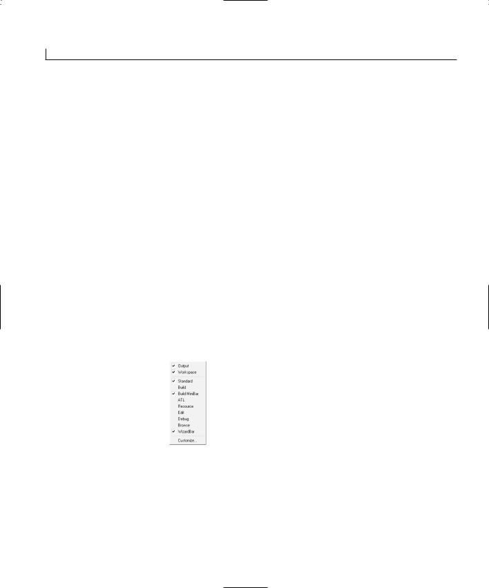
The Developer Studio provides two easy ways to rearrange your development environment. The first is by right-clicking your mouse over the toolbar area. This action opens the pop-up menu shown in Figure 1.2, allowing you to turn on and off various toolbars and panes.
FIGURE 1.2.
Toolbar on and off menu.
Another way that you can easily rearrange your development environment is to grab the double bars at the left end of any of the toolbars or panes with the mouse. You can drag the toolbars away from where they are currently docked, making them floating toolbars, as in Figure 1.3. You can drag these toolbars (and panes) to any other edge of the Developer Studio to dock them in a new spot. Even when the toolbars are docked, you can use the double bars to drag the toolbar left and right to place the toolbar where you want it to be located.
Building Your First Visual C++ Application |
11 |
FIGURE 1.3.
Example of a floating |
1 |
|
|
minibar. |
|
Note
On the workspace and Output panes, the double bars that you can use to drag the pane around the Developer Studio environment might appear on the top of the pane or on the left side, depending on how and where the pane is docked.
Starting Your First Project
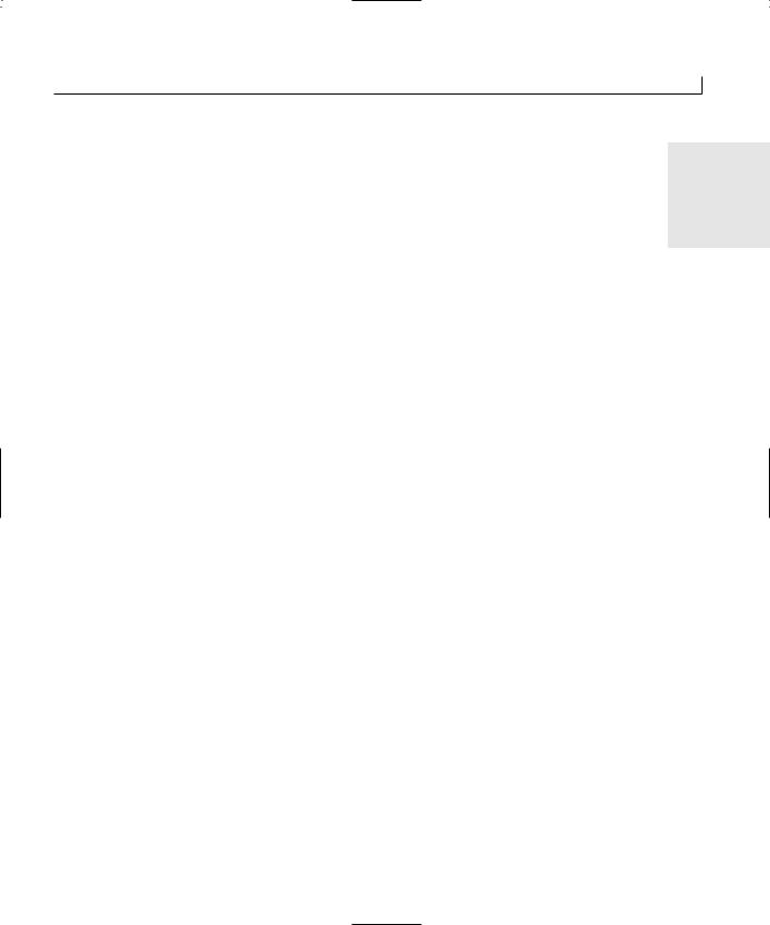
For your first Visual C++ application, you are going to create a simple application that presents the user with two buttons, as in Figure 1.4. The first button will present the user with a simple greeting message, shown in Figure 1.5, and the second button will close the application. In building this application, you will need to do the following things:
1.Create a new project workspace.
2.Use the Application Wizard to create the application framework.
3.Rearrange the dialog that is automatically created by the Application Wizard to resemble how you want the application to look.
4.Add the C++ code to show the greeting to the user.
5.Create a new icon for the application.
FIGURE 1.4.
Your first Visual C++ application.
FIGURE 1.5.
If the user clicks the first button, a simple greeting is shown.
Creating the Project Workspace
Every application development project needs its own project workspace in Visual C++. The workspace includes the directories where the application source code is kept, as well
12 |
Day 1 |
as the directories where the various build configuration files are located. You can create a new project workspace by following these steps:
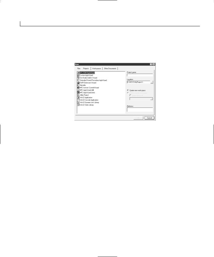
1. Select File | New. This opens the New Wizard shown in Figure 1.6.
FIGURE 1.6.
The New Wizard.
2.On the Projects tab, select MFC AppWizard (exe).
3.Type a name for your project, such as Hello, in the Project Name field.
4.Click OK. This causes the New Wizard to do two things: create a project directory (specified in the Location field) and then start the AppWizard.
Using the Application Wizard to Create the
Application Shell
The AppWizard asks you a series of questions about what type of application you are building and what features and functionality you need. It uses this information to create a shell of an application that you can immediately compile and run. This shell provides you with the basic infrastructure that you need to build your application around. You will see how this works as you follow these steps:
1.In Step 1 of the AppWizard, specify that you want to create a Dialog-based application. Click Next at the bottom of the wizard.
2.In Step 2 of the AppWizard, the wizard asks you about a number of features that you can include in your application. You can uncheck the option for including support for ActiveX controls if you will not be using any ActiveX controls in your application. Because you won’t be using any ActiveX controls in today’s application, go ahead and uncheck this box.
3.In the field near the bottom of the wizard, delete the project name (Hello) and type in the title that you want to appear in the title bar of the main application window,
Building Your First Visual C++ Application |
13 |
such as My First Visual C++ Application. Click Next at the bottom of the
wizard. |
1 |
|
4.In Step 3 of the AppWizard, leave the defaults for including source file comments and using the MFC library as a DLL. Click Next at the bottom of the wizard to proceed to the final AppWizard step.
5.The final step of the AppWizard shows you the C++ classes that the AppWizard will create for your application. Click Finish to let AppWizard generate your application shell.
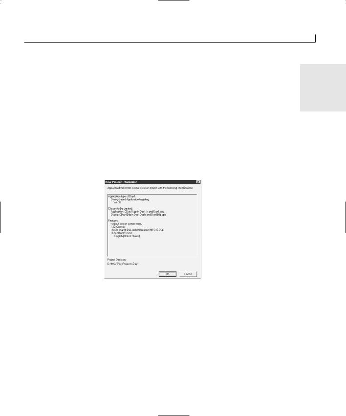
6.Before AppWizard creates your application shell, it presents you with a list of what it is going to put into the application shell, as shown in Figure 1.7, based on the options you selected when going through the AppWizard. Click OK and AppWizard generates your application.
FIGURE 1.7.
The New Project
Information screen.
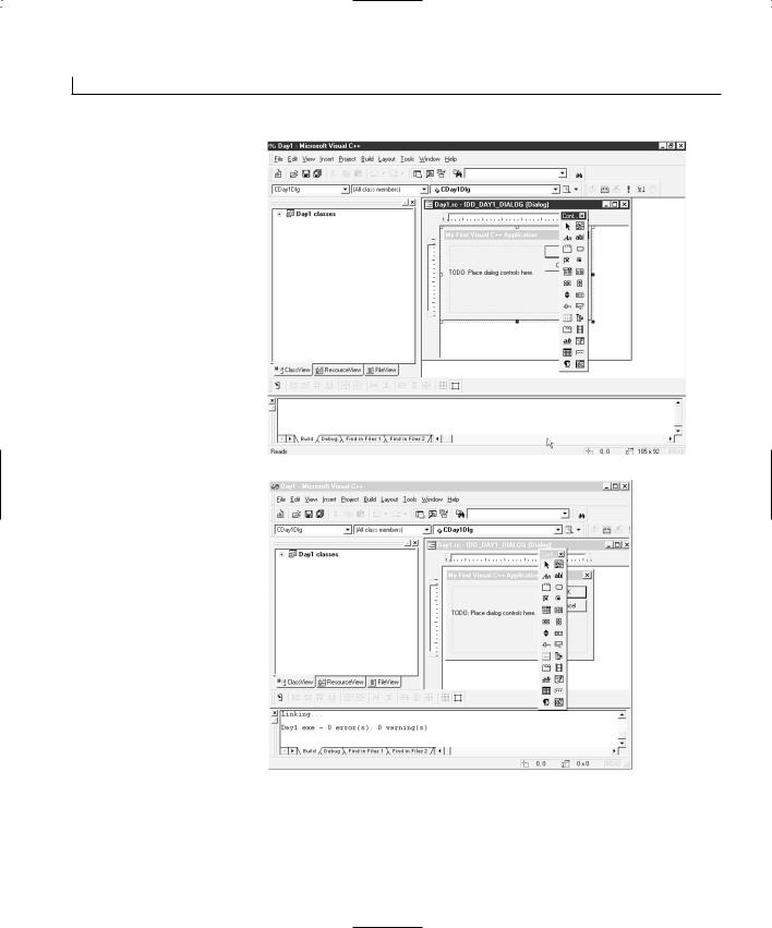
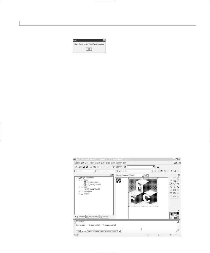
7.After the AppWizard generates your application shell, you are returned to the Developer Studio environment. You will notice that the workspace pane now presents you with a tree view of the classes in your application shell, as in Figure 1.8. You might also be presented with the main dialog window in the editor area of the Developer Studio area.
8.Select Build | Build Hello.exe to compile your application.
9.As the Visual C++ compiler builds your application, you see progress and other compiler messages scroll by in the Output pane. After your application is built, the Output pane should display a message telling you that there were no errors or warnings, as in Figure 1.9.
14 |
Day 1 |
FIGURE 1.8.
Your workspace with a tree view of the project’s classes.
FIGURE 1.9.
The Output pane displays any compiler errors.
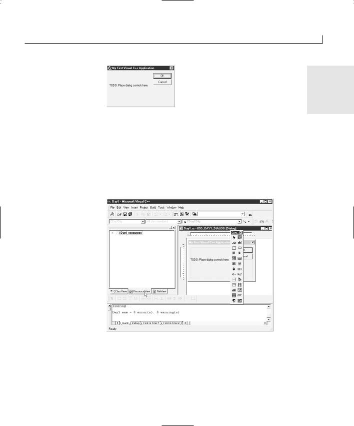
10.Select Build | Execute Hello.exe to run your application.
11.Your application presents a dialog with a T O D O message and OK and Cancel buttons, as shown in Figure 1.10. You can click either button to close the application.
Building Your First Visual C++ Application |
15 |
FIGURE 1.10.
The unmodified appli- |
1 |
|
|
cation shell. |
|
Designing Your Application Window
Now that you have a running application shell, you need to turn your focus to the window layout of your application. Even though the main dialog window may already be available for painting in the editor area, you should still navigate to find the dialog window in the workspace so that you can easily find the window in subsequent development efforts. To redesign the layout of your application dialog, follow these steps:
1. Select the Resource View tab in the workspace pane, as in Figure 1.11.
FIGURE 1.11.
The Resource View tab in the workspace pane.
2.Expand the resources tree to display the available dialogs. At this point, you can double-click the IDD_DAY1_DIALOG dialog to open the window in the Developer Studio editor area.
3.Select the text displayed in the dialog and delete it using the Delete key.
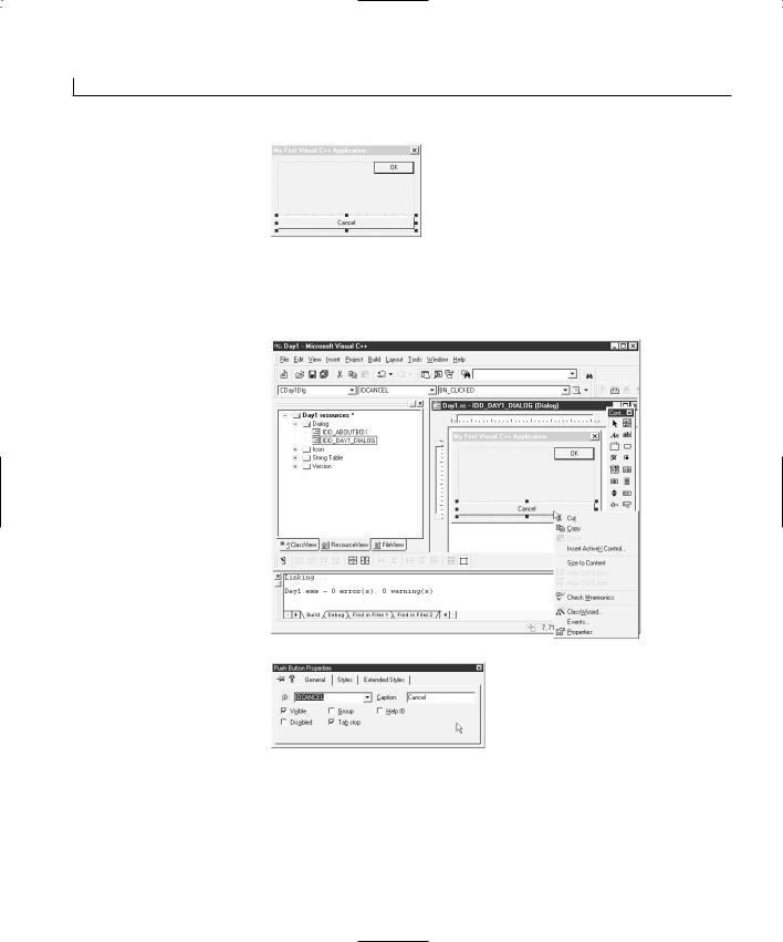
4.Select the Cancel button, drag it down to the bottom of the dialog, and resize it so that it is the full width of the layout area of the window, as in Figure 1.12.
16 |
Day 1 |
FIGURE 1.12.
Positioning the Cancel button.
5.Right-click the mouse over the Cancel button, opening the pop-up menu in Figure 1.13. Select Properties from the menu, and the properties dialog in Figure 1.14 opens.
FIGURE 1.13.
Right-clicking the mouse to open a popup menu.
FIGURE 1.14.
The Cancel button properties dialog.
6.Change the value in the Caption field to &Close. Close the properties dialog by clicking the Close icon in the upper-right corner of the dialog.
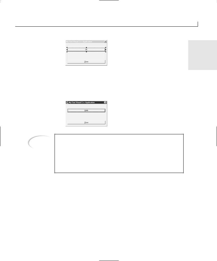
7.Move and resize the OK button to around the middle of the window, as in Figure 1.15.
Building Your First Visual C++ Application |
17 |
FIGURE 1.15.
Positioning the OK |
1 |
|
|
button. |
|
8.On the OK button properties dialog, change the ID value to IDHELLO and the caption to &Hello.
9.Now when you compile and run your application, it will look like what you’ve just designed, as shown in Figure 1.16.
FIGURE 1.16.
Running your redesigned application.
Note
If you play with your application, you will notice that the Close button still closes the application. However, the Hello button no longer does anything because you changed the ID of the button. MFC applications contain a series of macros in the source code that determine which functions to call based on the ID and event message of each control in the application. Because you changed the ID of the Hello button, these macros no longer know which function to call when the button is clicked.
Adding Code to Your Application
You can attach code to your dialog through the Visual C++ Class Wizard. You can use the Class Wizard to build the table of Windows messages that the application might receive, including the functions they should be passed to for processing, that the MFC macros use for attaching functionality to window controls. You can attach the functionality for this first application by following these steps:
1.To attach some functionality to the Hello button, right-click over the button and select Class Wizard from the pop-up menu.
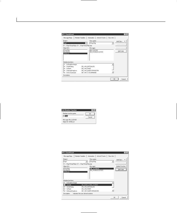
2.If you had the Hello button selected when you opened the Class Wizard, it is already selected in the list of available Object IDs, as in Figure 1.17.
18 |
Day 1 |
FIGURE 1.17.
The Class Wizard.
3.With IDHELLO selected in the Object ID list, select BN_CLICKED in the list of messages and click Add Function. This opens the Add Member Function dialog shown in Figure 1.18. This dialog contains a suggestion for the function name. Click OK to create the function and add it to the message map.
FIGURE 1.18.
The Class Wizard Add
Member Function dialog.
4.After the function is added for the click message on the Hello button, select the OnHello function in the list of available functions, as in Figure 1.19. Click the Edit Code button so that your cursor is positioned in the source code for the function, right at the position where you should add your functionality.
FIGURE 1.19.
The list of available functions in the Class
Wizard.
Building Your First Visual C++ Application |
19 |
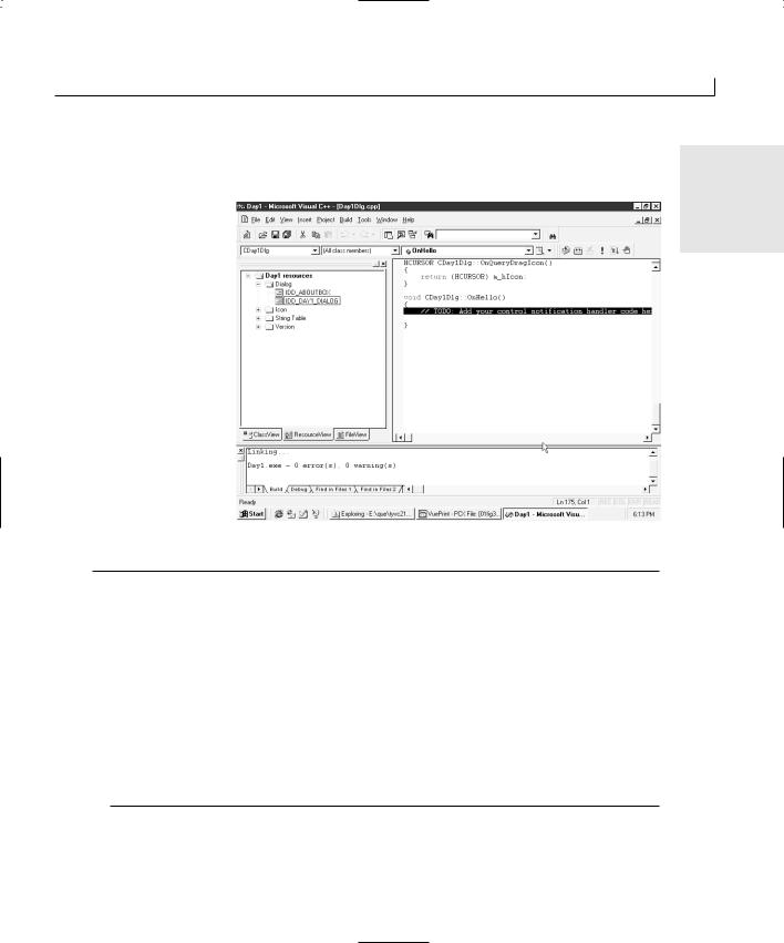
5. Add the code in Listing 1.1 just below the T O D O comment line, as shown in Figure
1.20. |
1 |
|
FIGURE 1.20.
Source code view where you insert Listing 1.1.
LISTING 1.1. HELLODLG.CPP—THE OnHello FUNCTION.
1:Void CHelloDlg::OnHello()
2:{
3:// TODO: Add your control notification handler code here
5:///////////////////////
6:// MY CODE STARTS HERE
7:///////////////////////
9:// Say hello to the user
10: MessageBox(“Hello. This is my first Visual C++ Application!”); 11:
12:///////////////////////
13:// MY CODE ENDS HERE
14:///////////////////////
15:}
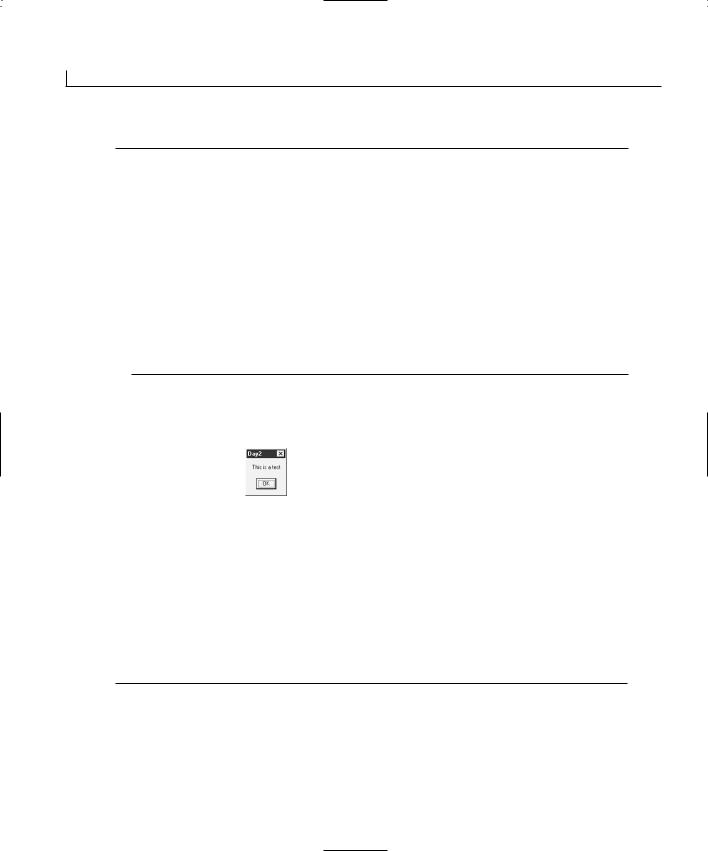
6.When you compile and run your application, the Hello button should display the message shown in Figure 1.21.
20 |
Day 1 |
FIGURE 1.21.
Now your application will say hello to you.
Finishing Touches
Now that your application is functionally complete, you can still add a few details to finish off the project. Those finishing touches include
•Creating the dialog box icon
•Adding maximize and minimize buttons
Creating the Dialog Box Icon
If you noticed the icon in the top-left corner of your application window, you saw three blocks with the letters M, F, and C. What does MFC have to do with your application? MFC stands for Microsoft Foundation Classes. Technically, it’s the C++ class library that your application is built with, but do you want to broadcast that to every user who sees your application? Most likely not. You need to edit the application icon to display an image that you do want to represent your application. Let’s get busy!
1.In the tree view of your application resources in the workspace pane, expand the icon branch and select the IDR_MAINFRAME icon, as in Figure 1.22. This brings the application icon into the editor area of the Developer Studio.
FIGURE 1.22.
The standard MFC icon.
Building Your First Visual C++ Application |
21 |
2. Using the painting tools provided, repaint the icon to display an image that you |
|
want to use to represent your application, as in Figure 1.23. |
1 |
|
FIGURE 1.23.
Your own custom icon for your application.
3.When you compile and run your application, you will notice your custom icon in the top-left corner of your application window. Click the icon and select About Hello from the drop-down menu.
4.On the About dialog that Visual C++ created for you, you can see a large version of your custom icon in all its glory, as shown in Figure 1.24.
FIGURE 1.24.
Your application’s About window.
Note
When you open an application icon in the icon designer, the icon is sized by default at 32×32. You can also select a 16×16 size icon from the drop-down list box just above where you are drawing the icon. You should draw both of these icons because there are some instances in which the large icon will be displayed and some instance in which the small icon will be shown. You will want both icons to show the same image to represent your application.
Adding Maximize and Minimize Buttons
In the dialog editor, where you design your application window, you can add the minimize and maximize buttons to the title bar of your application window by following these steps:
1.Select the dialog window itself as if you were going to resize the window.
2.Using the pop-up menu (from right-clicking the mouse), select the dialog properties.
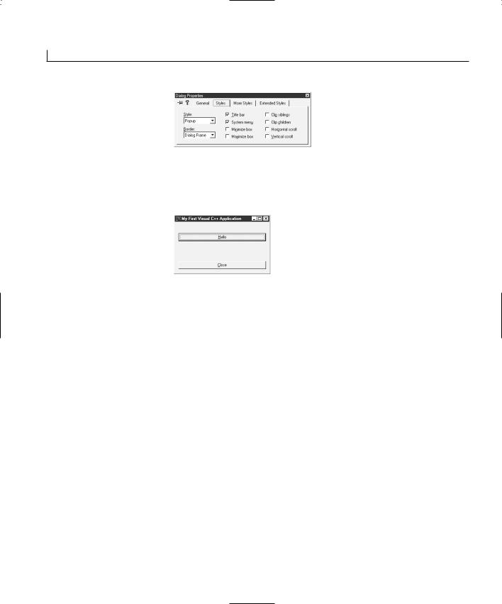
3.Select the Styles tab, as shown in Figure 1.25.
22 |
Day 1 |
FIGURE 1.25.
Turning the minimize and maximize buttons on and off.
4.After you turn on the minimize and maximize boxes, you can compile and run your application. The minimize and maximize buttons appear on the title bar, as in Figure 1.26.
FIGURE 1.26.
The application window with the minimize and maximize buttons.
Summary
Today you got your first taste of building applications using Visual C++. You learned about the different areas of the Visual C++ Developer Studio and what function each of these areas serves. You also learned how you can rearrange the Developer Studio environment to suit the way you work. You also learned how you can use the Visual C++ wizards to create an application shell and then attach functionality to the visual components that you place on your application windows.
Q&A
QHow can I change the title on the message box, instead of using the application name?
ABy default, the message box window uses the application name as the window title. You can change this by adding a second text string to the MessageBox function call. The first string is always the message to be displayed, and the second string is used as the window title. For example, the OnHello function would look like
// Say hello to the user
MessageBox(“Hello. This is my first Visual C++ Application!”, “My First Application”);
Building Your First Visual C++ Application |
23 |
Q Can I change the text on the About window to give my company name and |
|
more detailed copyright information? |
1 |
|
AYes, the About window is in the Dialogs folder in the Resources View tab of the workspace pane. If you double-click the IDD_ABOUTBOX dialog, the About box will be opened in the dialog designer, where you can redesign it however you want.
Workshop
The Workshop provides quiz questions to help solidify your understanding of the material covered and exercises to provide you with experience in using what you’ve learned. The answers to the quiz questions and exercises are provided in Appendix B, “Answers.”
Quiz
1.How do you change the caption on a button?
2.What can you do with the Visual C++ AppWizard?
3.How do you attach functionality to the click of a button?
Exercise
Add a second button to the About window in your application. Have the button display a different message from the one on the first window.

WEEK 1
DAY 2
Using Controls in Your
Application
Some of the things that you will find in just about every Windows application are buttons, check boxes, text fields, and drop-down list boxes. These are known as controls, and many of these controls are built into the operating system itself. With Visual C++, using these common controls is as easy as placing them on a dialog window with a drag-and-drop window design method. Today you are going to learn
•What the basic controls in Visual C++ are
•How to declare and attach variables to a controls
•How to synchronize the values between a control and a variable
•How to specify the order users navigate around your application windows
•How to trigger actions with controls
•How to manipulate and alter the appearance of controls (while your application is running)
26 |
Day 2 |
The Basic Windows Controls
Several standard controls are built into the Windows operating system, including such things as sliders, tree and list controls, progress bars, and so on. However, today you will work with a half dozen controls that appear in just about every Windows application:
•Static text
•Edit box
•Command button
•Check box
•Radio button
•Drop-down list box (also known as a combo box)
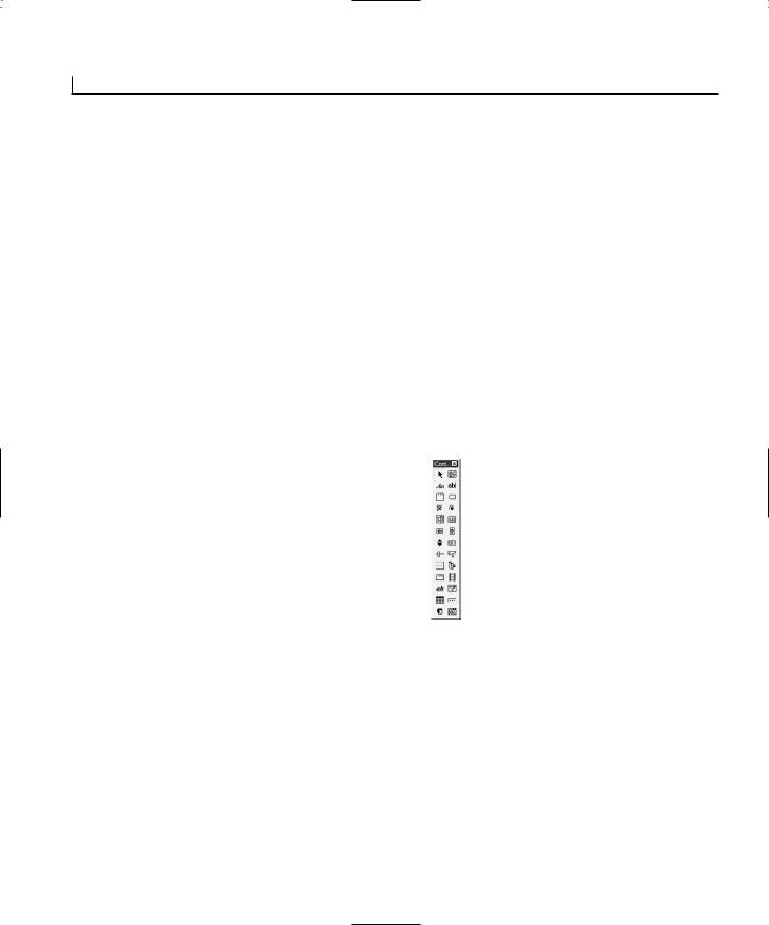
These and other controls are readily available for use in Visual C++ applications. They can be found on the controls palette in the Dialog Painter editor in the Developer Studio, as shown in Figure 2.1.
FIGURE 2.1.
The standard controls |
Select |
|
|
|
|
|
|
Picture |
||||||||
|
|
|
|
|||||||||||||
Group Box |
|
Static Text |
|
|
|
|
|
|
|
|
Edit Box |
|||||
|
|
|
|
|
|
|||||||||||
available on the |
|
|
|
|
|
|
Command Button |
|||||||||
|
Check Box |
|
|
|
|
|
|
|
|
|||||||
Control palette. |
|
|
|
|
|
|
|
|
|
|
Radio Button |
|||||
|
|
|
|
|
|
|||||||||||
|
|
|
|
|
|
|
|
|
|
|
|
List Box |
||||
Drop-Down |
|
|
Horizontal Scrollbar |
|
|
|
|
|
|
|
Vertical Scrollbar |
|||||
|
|
|
|
|
|
|
||||||||||
|
|
Spin |
|
|
|
|
|
|
|
|
|
|
Progress Bar |
|||
List Box |
|
|
|
|
|
|
||||||||||
|
|
Slider |
|
|
|
|
|
|
|
|
|
|
Hot Key |
|||
(Combo Box) |
List Control |
|
|
|
|
|
|
|
|
|||||||
|
|
|
|
|
|
|
|
|
|
Tree Control |
||||||
|
|
|
|
|
|
|
|
|
||||||||
|
|
|
|
|
Tab Control |
|
|
|
|
|
|
|
Animate |
|||
|
|
|
|
|
|
|
|
|
|
|
||||||
|
|
Rich Text Edit |
|
|
|
|
|
Date/Time Picker |
||||||||
|
|
|
|
|
|
|||||||||||
|
|
|
|
|
Month Calendar |
|
|
|
|
|
|
|
IP Address |
|||
|
|
|
|
|
|
|
|
|||||||||
|
|
Custom Control |
|
|
|
|
Extended Combo |
|||||||||
|
|
|
|
|
|
|||||||||||
|
|
|
|
|
|
|
|
|
|
|
|
|
|
Box |
||
The Static Text Control
You use the static text control to present text to the user. The user will not be able to change the text or otherwise interact with the control. Static text is intended as a readonly control. However, you can easily change the text displayed by the control as your application is running through the code you create for your application.
The Edit Box Control
An edit box allows the user to enter or change text. The edit box is one of the primary tools for allowing the user to enter specific information that your application needs. It is a control that allows the user to type a specific amount of text, which you can capture
Using Controls in Your Application |
27 |
and use for any needed purpose. The edit box accepts plain text only; no formatting is available to the user.
The Command Button Control
A command button is a button that the user can press to trigger some action. Command buttons have a textual label that can give users some idea of what will happen when they click that button. Buttons can also have images as part of the button, allowing you to
place an image on the button—alone or along with a textual description—to convey what 2 the button does.
The Check Box Control
A check box is a square that the user can click to check (×) or uncheck. The check box control is used to turn a particular value on and off. They are basically on/off switches with an occasional third, in-between state. You normally use check boxes to control discrete, on/off-type variables.
The Radio Button Control
A radio button is a circle that the user can click to fill with a black spot. The radio button is similar to the check box control, but it is used in a group of two or more where only one of the values can be in the on state at a time. You normally use radio buttons in groups of at least three, surrounded by a group box. The group box allows each group of radio buttons to be independent so that only one radio button in each group can be in the on state at any time.
The Drop-Down List Box Control
A drop-down list box, or combo control, is an edit box with a list of available values attached. You use the drop-down list box to provide a list of choices, from which the user may select one value from the list. Sometimes, the user is given the option of typing in his own value when a suitable one isn’t provided in the list.
Adding Controls to Your Window
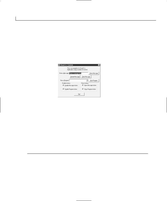
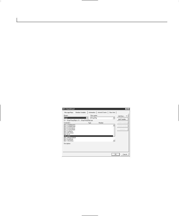
The application you are going to build today will have a number of controls on a single dialog window, as shown in Figure 2.2. These controls have a number of different functions. At the top of the window is an edit field where the user can enter a message that displays in a message box when he or she clicks the button beside the field. Below this edit field are two buttons that either populate the edit field with a default message or clear the edit field. Below these buttons is a drop-down list box that contains a list of
28 |
Day 2 |
standard Windows applications. When the user selects one of these programs and then clicks the button beside the drop-down list, the selected program will run. Next are two groups of check boxes that affect the controls you add to the top half of the dialog: the controls for displaying a user message and the controls for running another program. The left set of check boxes will enable and disable each group of controls you provide. The right set of check boxes will show and hide each group of controls. At the bottom of the dialog box is a button that can be clicked to close the application.
FIGURE 2.2.
Today’s application will use a number of standard controls.
Creating the Application Shell and Dialog Layout
Using what you learned yesterday, create a new application shell and design the application dialog layout as follows:
1.Create a new AppWizard workspace project, calling the project Day2.
2.Use the same settings in the AppWizard as you used yesterday; specify the dialog title Visual C++ Controls.
3.After you create the application shell, lay out the main dialog as shown earlier in Figure 2.2.
4.Configure the control properties as specified in Table 2.1.
TABLE 2.1. PROPERTY SETTINGS FOR THE CONTROLS ON THE APPLICATION DIALOG.
Object |
Property |
Setting |
Static Text |
ID |
IDC_STATIC |
|
Caption |
This is an example of a Visual C++ |
|
Application using a number of controls. |
|
Static Text |
ID |
|
Caption |
Static Text |
ID |
|
Caption |
IDC_STATICMSG
Enter a &Message:
IDC_STATICPGM
Run a &Program:
|
Using Controls in Your Application |
29 |
|
Object |
Property |
Setting |
|
Edit Box |
ID |
Button |
ID |
|
Caption |
Button |
ID |
|
Caption |
Button |
ID |
|
Caption |
Button |
ID |
|
Caption |
Button |
ID |
|
Caption |
Combo Box |
ID |
Group Box |
ID |
|
Caption |
Group Box |
ID |
|
Caption |
Check Box |
ID |
|
Caption |
Check Box |
ID |
|
Caption |
Check Box |
ID |
|
Caption |
Check Box |
ID |
|
Caption |
IDC_MSG |
|
IDC_SHWMSG |
|
&Show Message |
|
IDC_DFLTMSG |
|
&Default Message |
2 |
IDC_CLRMSG |
&Clear Message
IDC_RUNPGM
&Run Program
IDC_EXIT
E&xit
IDC_PROGTORUN
IDC_STATIC
Enable Actions
IDC_STATIC
Show Actions
IDC_CKENBLMSG
&Enable Message Action
IDC_CKENBLPGM
E&nable Program Action
IDC_CKSHWMSG
S&how Message Action
IDC_CKSHWPGM
Sh&ow Program Action
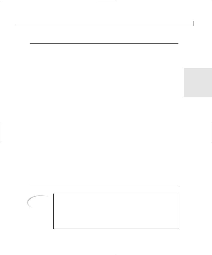
Tip
When adding a combo box control to the window, it is important that you click and drag the area for the control as large as you want the drop-down list to be. After you draw the control on the window, you can resize the width of the control as you would normally expect to do. To resize how far the list drops down, you need to click the arrow, as if you were trying to trigger the drop-down list while the application was running.
30 |
Day 2 |
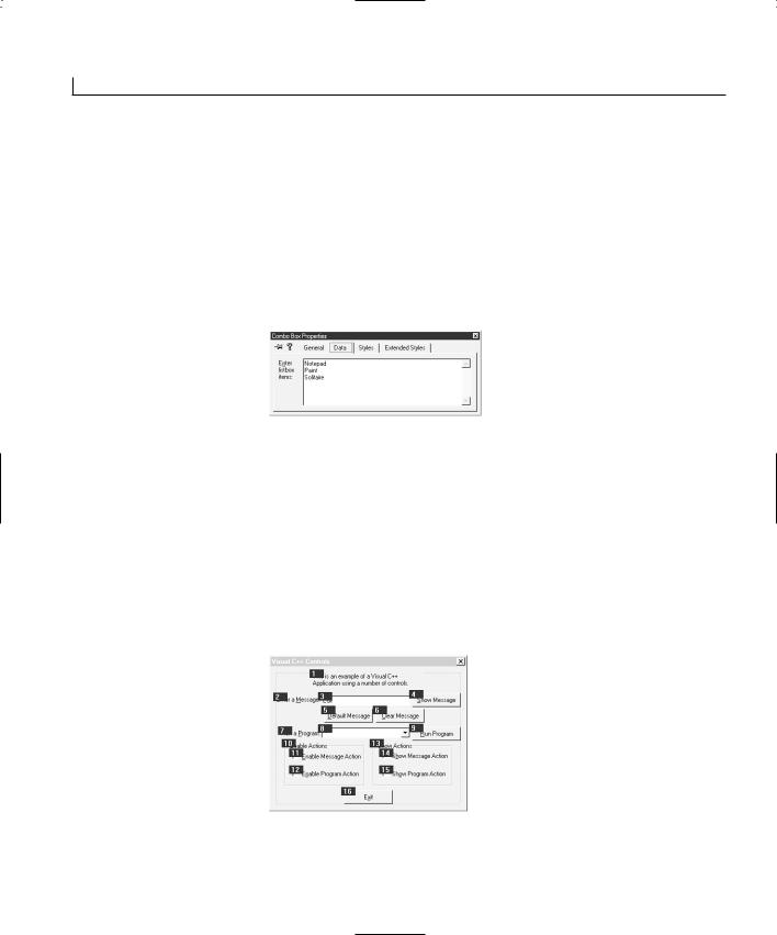
5.After you place all these controls on the dialog window and configure all their properties, reopen the properties dialog for the combo box that you placed on the window. On the Data tab of the properties dialog, enter the following values, using a Control+Enter key combination to add the second and third items, as shown in Figure 2.3.
•Notepad
•Paint
•Solitaire
FIGURE 2.3.
Use the properties dialog to add entries in the combo box’s dropdown list.
Specifying the Control Tab Order
Now that you have all the controls laid out on the window, you need to make sure that the user navigates in the order you want if he or she uses the Tab key to move around the window. You can specify the tab order by following these steps:
1.Select either the dialog window or one of the controls on the window in the editing area of the Developer Studio.
2.Choose Layout | Tab Order from the menu. By turning on the Tab Order, you see a number beside each of the controls on the window. The numbers indicate the order in which the dialog will be navigated, as shown in Figure 2.4.
FIGURE 2.4.
Turning on Tab Order shows the order in which the dialog will be navigated.
3.Using the mouse, click each of the number boxes in the order that you want the user to navigate the window. The controls will renumber themselves to match the order in which you selected them.
Using Controls in Your Application |
31 |
4.Once you specify the tab order, select Layout | Tab Order once again to return to the layout editor.
Note |
Any static text that has a mnemonic should appear just before the control |
|
that accompanies the text in the tab order. Because the user cannot interact |
|
|
|
|
|
|
with the static text, when the user chooses the mnemonic, the focus will go |
|
|
directly to the next control in the tab order. |
2 |
|
|
|
|
|
|
A mnemonic is the underlined character in the caption on a button, check box, menu, or other control label. The user can press this underlined character and the Alt key at the same time to go directly to that control or to trigger the clicked event on the control. You specify a mnemonic by placing an ampersand (&) in front of the character to be used as the mnemonic when you type the Caption value. It is important to make certain that you do not use the same mnemonic more than once on the same window, or set of menus, because the user can get confused when choosing a mnemonic doesn’t result in the action that he or she expects.
One last thing that you want to do before getting into the details of the application code is check your mnemonics to make certain that there are no conflicts in your controls. Follow these steps:
1.Select the dialog window or one of the controls in the layout editor. Right-click the mouse and select Check Mnemonics.
2.If there are no conflicts in your mnemonics, Visual C++ returns a message box dialog, letting you know that there are no conflicts (see Figure 2.5).
FIGURE 2.5.
The mnemonic checker tells you whether there are conflicts.
3.If any conflicts exist, the dialog indicates the conflicting letter and gives you the option of automatically selecting the controls containing the conflicting mnemonics, as in Figure 2.6.
FIGURE 2.6.
Duplicate mnemonics can be automatically
selected.
32 |
Day 2 |
Attaching Variables to Your Controls
At this point, if you’ve programmed using Visual Basic or PowerBuilder, you probably figure that you’re ready to start slinging some code. Well, with Visual C++, it’s not quite the same process. Before you can begin coding, you have to assign variables to each of the controls that will have a value attached—everything except the static text and the command buttons. You will interact with these variables when you write the code for your application. The values that the user enters into the screen controls are placed into these variables for use in the application code. Likewise, any values that your application code places into these variables are updated in the controls on the window for the user to see.
How do you declare these variables and associate them with the controls that you placed on the window? Follow these steps:
1.Open the Class Wizard, as you learned yesterday.
2.Select the Member Variables tab, as shown in Figure 2.7.
FIGURE 2.7.
The Member Variables tab on the Class
Wizard is where you add variables to controls.
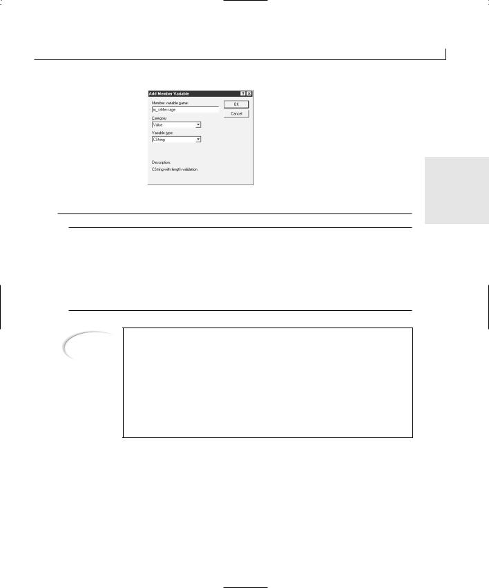
3. Select the ID of one of the controls that you need to attach a variable to, such as
IDC_MSG.
4.Click the Add Variable button.
5.In the Add Member Variable dialog, enter the variable name, specifying the category and variable type, as shown in Figure 2.8. Click OK.
6.Repeat steps 3 through 5 for all the other controls for which you need to add variables. You should add the variables for your application as listed in Table 2.2.
Using Controls in Your Application |
33 |
FIGURE 2.8.
Adding a variable to a control.
2
TABLE 2.2. VARIABLES FOR APPLICATION CONTROLS.
Control |
Variable Name |
Category |
Type |
IDC_MSG |
m_strMessage |
IDC_PROGTORUN |
m_strProgToRun |
IDC_CKENBLMSG |
m_bEnableMsg |
IDC_CKENBLPGM |
m_bEnablePgm |
IDC_CKSHWMSG |
m_bShowMsg |
IDC_CKSHWPGM |
m_bShowPgm |
Value |
CString |
Value |
CString |
Value |
BOOL |
Value |
BOOL |
Value |
BOOL |
Value |
BOOL |
Tip
All these variables are prefixed with m _ because they are class member variables. This is an MFC naming convention. After the m _, a form of Hungarian notation is used, in which the next few letters describe the variable type. In this case, b means boolean, and str indicates that the variable is a string.
You’ll see this naming convention in use in this book and other books about programming with Visual C++ and MFC. Following this naming convention will make your code more readable for other programmers; knowing the convention will make it easier for you to read other programmer’s code as well.
7.After you add all the necessary variables, click the OK button to close the Class Wizard.
Attaching Functionality to the Controls
Before you begin adding code to all the controls on your application window, you need to add a little bit of code to initialize the variables, setting starting values for most of them. Do this by following these steps:
34 |
Day 2 |
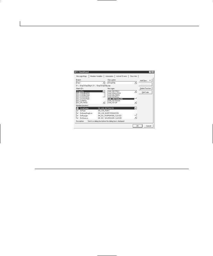
1.Using the Class Wizard, on the Message Maps tab, select the OnInitDialog function in the list of member functions. You can do this by finding the function in the Member Functions list, or by selecting the CDay2Dlg object in the list of object IDs and then selecting the WM_INITDIALOG message in the messages list, as shown in Figure 2.9.
FIGURE 2.9.
You can use the Class
Wizard to locate existing functions.
2.Click Edit Code to be taken to the source code for the OnInitDialog function.
3.Find the T O D O marker, which indicates where to begin adding your code, and add the code in Listing 2.1.
LISTING 2.1. DAY2DLG.CPP—THE OnInitDialog FUNCTION IS WHERE YOU NEED TO ADD INITIALIZATION CODE.
1:BOOL CDay2Dlg::OnInitDialog()
2:{
3:CDialog::OnInitDialog();
4:
9: // TODO: Add extra initialization here 10:
11:///////////////////////
12:// MY CODE STARTS HERE
13:///////////////////////
15:// Put a default message in the message edit
16:m_strMessage = “Place a message here”;
18:// Set all of the check boxes to checked
Using Controls in Your Application |
35 |
19:m_bShowMsg = TRUE;
20:m_bShowPgm = TRUE;
21:m_bEnableMsg = TRUE;
22:m_bEnablePgm = TRUE;
24:// Update the dialog with the values
25:UpdateData(FALSE);
26: |
|
|
27: |
/////////////////////// |
2 |
28: |
// MY CODE ENDS HERE |
|
29: |
/////////////////////// |
|
30: |
|
|
31:return TRUE; // return TRUE unless you set the focus to acontrol
32:}
Note
There is more code in the OnInitDialog function than has been included in Listing 2.1. I won’t include all the code for every function in the code listings throughout this book as a means of focusing on the code that you need to add or modify (and as a means of keeping this book down to a reasonable size). You are welcome to look at the code that has been left out, to learn what it is and what it does, as you build your understanding of MFC and Visual C++.
Note
If you’ve programmed in C or C++ before, you’ve noticed that you are setting the value of the m_strMessage variable in a very un–C-like manner. It looks more like how you would expect to set a string variable in Visual Basic or PowerBuilder. That’s because this variable is a CString type variable. The CString class enables you to work with strings in a Visual C++ application in much the same way that you would work with strings in one of these other programming languages. However, because this is the C++ programming language, you still need to add a semicolon at the end of each command.
This initialization code is simple. You are setting an initial message in the edit box that you will use to display messages for the user. Next, you are setting all the check boxes to the checked state. It’s the last line of the code you added to this function that you really need to notice.
The UpdateData function is the key to working with control variables in Visual C++. This function takes the data in the variables and updates the controls on the screen with the variable values. It also takes the data from the controls and populates the attached vari-

36 |
Day 2 |
ables with any values changed by the user. This process is controlled by the argument passed into the UpdateData function. If the argument is FALSE, the values in the variables are passed to the controls on the window. If the argument is TRUE, the variables are updated with whatever appears in the controls on the window. As a result, which value you pass this function depends on which direction you need to update. After you update one or more variables in your code, then you need to call UpdateData, passing it FALSE as its argument. If you need to read the variables to get their current value, then you need to call UpdateData with a TRUE value before you read any of the variables. You’ll get the hang of this as you add more code to your application.
Closing the Application
The first thing that you want to take care of is making sure that the user can close your application. Because you deleted the OK and Cancel buttons and added a new button for closing the application window, you need to place code into the function called by the Exit button to close the window. To do this, follow these steps:
1.Using the Class Wizard, add a function for the IDC_EXIT object on the BN_CLICKED message, as you learned to do yesterday.
2.Click the Edit Code button to take you to the new function that you just added.
3.Enter the code in Listing 2.2.
LISTING 2.2. DAY2DLG.CPP—THE OnExit FUNCTION.
1:void CDay2Dlg::OnExit()
2:{
3:// TODO: Add your control notification handler code here
5:///////////////////////
6:// MY CODE STARTS HERE
7:///////////////////////
9:// Exit the program
10: OnOK(); 11:
12:///////////////////////
13:// MY CODE ENDS HERE
14:///////////////////////
15:}
A single function call within the OnExit function closes the Window and exits the application. Where did this OnOK function come from, and why didn’t you have to call it in yesterday’s application? Two functions, OnOK and OnCancel, are built into the ancestor
Using Controls in Your Application |
37 |
CDialog class from which your CDay2Dlg class is inherited. In the CDialog class, the message map already has the object IDs of the OK and Cancel buttons attached to the OnOK and OnCancel buttons so that buttons with these IDs automatically call these
functions. If you had specified the Exit button’s object ID as IDOK, you would not have needed to add any code to the button unless you wanted to override the base OnOK functionality.
Showing the User’s Message |
2 |
Showing the message that the user typed into the edit box should be easy because it’s similar to what you did in yesterday’s application. You can add a function to the Show Message button and call the MessageBox function, as in Listing 2.3.
LISTING 2.3. DAY2DLG.CPP—THE OnShwmsg FUNCTION DISPLAYS THE USER MESSAGE.
1:void CDay2Dlg::OnShwmsg()
2:{
3:// TODO: Add your control notification handler code here
5:///////////////////////
6:// MY CODE STARTS HERE
7:///////////////////////
9:// Display the message for the user
10: MessageBox(m_strMessage); 11:
12:///////////////////////
13:// MY CODE ENDS HERE
14:///////////////////////
15:}
If you compile and run the application at this point, you’ll see one problem with this code. It displays the string that you initialized the m_strMessage variable within the OnInitDialog function. It doesn’t display what you type into the edit box. This happens because the variable hasn’t been updated with the contents of the control on the window yet. You need to call UpdateData, passing it a TRUE value, to take the values of the controls and update the variables before calling the MessageBox function. Alter the OnShwmsg function as in Listing 2.4.
LISTING 2.4. DAY2DLG.CPP—UPDATED OnShwmsg FUNCTION.
1:void CDay2Dlg::OnShwmsg()
2:{
continues
38 |
Day 2 |
LISTING 2.4. CONTINUED
3: // TODO: Add your control notification handler code here 4:
5:///////////////////////
6:// MY CODE STARTS HERE
7:///////////////////////
9:// Update the message variable with what the user entered
10: UpdateData(TRUE); 11:
12:// Display the message for the user
13:MessageBox(m_strMessage);
14:
15:///////////////////////
16:// MY CODE ENDS HERE
17:///////////////////////
18:}
Now if you compile and run your application, you should be able to display the message you type into the edit box, as shown in Figure 2.10.
FIGURE 2.10.
The message entered in the edit box is displayed to the user.
Clearing the User’s Message
If the user prefers the edit box to be cleared before he or she types a message, you can attach a function to the Clear Message button to clear the contents. You can add this function through the Class Wizard in the usual way. The functionality is a simple matter of setting the m_strMessage variable to an empty string and then updating the controls on the window to reflect this. The code to do this is in Listing 2.5.
LISTING 2.5. DAY2DLG.CPP—THE OnClrmsg FUNCTION.
1:void CDay2Dlg::OnClrmsg()
2:{
3:// TODO: Add your control notification handler code here
5:///////////////////////
6:// MY CODE STARTS HERE
7:///////////////////////
9:// Clear the message
Using Controls in Your Application |
39 |
10: m_strMessage = “”; 11:
12:// Update the screen
13:UpdateData(FALSE);
15: ///////////////////////
16: // MY CODE ENDS HERE 17: ///////////////////////
18: }
2
Disabling and Hiding the Message Controls
The last thing that you want to do with the message controls is add functionality to the Enable Message Action and Show Message Action check boxes. The first of these check boxes enables or disables the controls dealing with displaying the user message. When the check box is in a checked state, the controls are all enabled. When the check box is in an unchecked state, all those same controls are disabled. In a likewise fashion, the second check box shows and hides this same set of controls. The code for these two functions is in Listing 2.6.
LISTING 2.6. DAY2DLG.CPP—THE FUNCTIONS FOR THE ENABLE AND SHOW MESSAGE ACTIONS CHECK BOXES.
1:void CDay2Dlg::OnCkenblmsg()
2:{
3:// TODO: Add your control notification handler code here
5:///////////////////////
6:// MY CODE STARTS HERE
7:///////////////////////
9:// Get the current values from the screen
10: UpdateData(TRUE); 11:
12:// Is the Enable Message Action check box checked?
13:if (m_bEnableMsg == TRUE)
14:{
15:// Yes, so enable all controls that have anything
16:// to do with showing the user message
17:GetDlgItem(IDC_MSG)->EnableWindow(TRUE);
18:GetDlgItem(IDC_SHWMSG)->EnableWindow(TRUE);
19:GetDlgItem(IDC_DFLTMSG)->EnableWindow(TRUE);
20:GetDlgItem(IDC_CLRMSG)->EnableWindow(TRUE);
21:GetDlgItem(IDC_STATICMSG)->EnableWindow(TRUE);
22:}
continues

40 |
Day 2 |
LISTING 2.6. CONTINUED
23:else
24:{
25:// No, so disable all controls that have anything
26:// to do with showing the user message
27:GetDlgItem(IDC_MSG)->EnableWindow(FALSE);
28:GetDlgItem(IDC_SHWMSG)->EnableWindow(FALSE);
29:GetDlgItem(IDC_DFLTMSG)->EnableWindow(FALSE);
30:GetDlgItem(IDC_CLRMSG)->EnableWindow(FALSE);
31:GetDlgItem(IDC_STATICMSG)->EnableWindow(FALSE);
32:}
33:
34:///////////////////////
35:// MY CODE ENDS HERE
36:///////////////////////
37:}
38:
39:void CDay2Dlg::OnCkshwmsg()
40:{
41:// TODO: Add your control notification handler code here
43:///////////////////////
44:// MY CODE STARTS HERE
45:///////////////////////
47:// Get the current values from the screen
48:UpdateData(TRUE);
49:
50:// Is the Show Message Action check box checked?
51:if (m_bShowMsg == TRUE)
52:{
53:// Yes, so show all controls that have anything
54:// to do with showing the user message
55:GetDlgItem(IDC_MSG)->ShowWindow(TRUE);
56:GetDlgItem(IDC_SHWMSG)->ShowWindow(TRUE);
57:GetDlgItem(IDC_DFLTMSG)->ShowWindow(TRUE);
58:GetDlgItem(IDC_CLRMSG)->ShowWindow(TRUE);
59:GetDlgItem(IDC_STATICMSG)->ShowWindow(TRUE);
60:}
61:else
62:{
63:// No, so hide all controls that have anything
64:// to do with showing the user message
65:GetDlgItem(IDC_MSG)->ShowWindow(FALSE);
66:GetDlgItem(IDC_SHWMSG)->ShowWindow(FALSE);
67:GetDlgItem(IDC_DFLTMSG)->ShowWindow(FALSE);
68:GetDlgItem(IDC_CLRMSG)->ShowWindow(FALSE);
69:GetDlgItem(IDC_STATICMSG)->ShowWindow(FALSE);
70:}
Using Controls in Your Application |
41 |
71:
72:///////////////////////
73:// MY CODE ENDS HERE
74:///////////////////////
75:}
By now, you should understand the first part of these functions. First, you update the
variables with the current values of the controls on the window. Next, you check the 2 value of the boolean variable attached to the appropriate check box. If the variable is
TRUE, you want to enable or show the control. If the variable if FALSE, you want to disable or hide the control.
At this point, the code begins to be harder to understand. The first function, GetDlgItem, is passed the ID of the control that you want to change. This function returns the object for that control. You can call this function to retrieve the object for any of the controls on the window while your application is running. The next part of each command is where a member function of the control object is called. The second function is a member function of the object returned by the first function. If you are not clear on how this works, then you might want to check out Appendix A, “C++ Review,” to brush up on your C++.
The second functions in these calls, EnableWindow and ShowWindow, look like they should be used on windows, not controls. Well, yes, they should be used on windows; they happen to be members of the CWnd class, which is an ancestor of the CDialog class from which your CDay2Dlg class is inherited. It just so happens that, in Windows, all controls are themselves windows, completely separate from the window on which they are placed. This allows you to treat controls as windows and to call windows functions on them. In fact, all the control classes are inherited from the CWnd class, revealing their true nature as windows.
If you compile and run your application now, you can try the Enable and Show Message
FIGURE 2.11.
The user message controls can now be dis-
abled.

42 |
Day 2 |
Action check boxes. They should work just fine, as shown in Figure 2.11.
Running Another Application
The last major piece of functionality to be implemented in your application is for the set of controls for running another program. If you remember, you added the names of three Windows applications into the combo box, and when you run your application, you can see these application names in the drop-down list. You can select any one of them, and the value area on the combo box is updated with that application name. With that part working as it should, you only need to add code to the Run Program button to actually get the value for the combo box and run the appropriate program. Once you create the function for the Run Program button using the Class Wizard, add the code in Listing 2.7 to the function.
LISTING 2.7. DAY2DLG.CPP—THE OnRunpgm FUNCTION STARTS OTHER WINDOWS APPLICA-
TIONS.
1:void CDay2Dlg::OnRunpgm()
2:{
3:// TODO: Add your control notification handler code here
5:///////////////////////
6:// MY CODE STARTS HERE
7:///////////////////////
9:// Get the current values from the screen
10: UpdateData(TRUE); 11:
12:// Declare a local variable for holding the program name
13:CString strPgmName;
14:
15:// Copy the program name to the local variable
16:strPgmName = m_strProgToRun;
17:
18:// Make the program name all uppercase
19:strPgmName.MakeUpper();
20:
21:// Did the user select to run the Paint program?
22:if (strPgmName == “PAINT”)
23:// Yes, run the Paint program
24:WinExec(“pbrush.exe”, SW_SHOW);
25:
26:// Did the user select to run the Notepad program?
27:if (strPgmName == “NOTEPAD”)
28:// Yes, run the Notepad program
29:WinExec(“notepad.exe”, SW_SHOW);
30:
Using Controls in Your Application |
43 |
31:// Did the user select to run the Solitaire program?
32:if (strPgmName == “SOLITAIRE”)
33:// Yes, run the Solitaire program
34:WinExec(“sol.exe”, SW_SHOW);
35:
36: ///////////////////////
37: // MY CODE ENDS HERE 38: ///////////////////////
39: }
2
As you expect, the first thing that you do in this function is call UpdateData to populate the variables with the values of the controls on the window. The next thing that you do, however, might seem a little pointless. You declare a new CString variable and copy the value of the combo box to it. Is this really necessary when the value is already in a CString variable? Well, it depends on how you want your application to behave. The next line in the code is a call to the CString function MakeUpper, which converts the string to all uppercase. If you use the CString variable that is attached to the combo box, the next time that UpdateData is called with FALSE as the argument, the value in the combo box is converted to uppercase. Considering that this is likely to happen at an odd time, this is probably not desirable behavior. That’s why you use an additional CString in this function.
Once you convert the string to all uppercase, you have a series of if statements that compare the string to the names of the various programs. When a match is found, the
Cautionfunction is called to run the application. Now, if you compile and run your you can select one of the applications in the drop-down list and run it by
clicking the Run Program button.
It is important to understand the difference in C and C++ between using a single equal sign (=) and a double equal sign (==). The single equal sign performs an assignment of the value on the right side of the equal sign to the variable on the left side of the equal sign. If a constant is on the left side of the equal sign, your program will not compile, and you’ll get a nice error message telling you that you cannot assign the value on the right to the constant on the left. The double equal sign (==) is used for comparison. It is
44 |
Day 2 |
Note
important to make certain that you use the double equal sign when you want to compare two values because if you use a single equal sign, you alter the value of the variable on the left. This confusion is one of the biggest sources of logic bugs in C/C++ programs.
The WinExec function is an obsolete Windows function. You really should use the CreateProcess function instead. However, the CreateProcess function has a number of arguments that are difficult to understand this early in programming using Visual C++. The WinExec function is still available and is implemented as a macro that calls the CreateProcess function. This allows you to use the much simpler WinExec function to run another application while still
using the function that Windows wants you to use.
Another API function that can be used to run another application is the ShellExecute function. This function was originally intended for opening or printing files, but can also be used to run other programs.
Summary
Today, you learned how you can use standard windows controls in a Visual C++ application. You learned how to declare and attach variables to each of these controls and how to synchronize the values between the controls and the variables. You also learned how you can manipulate the controls by retrieving the control objects using their object ID and how you can manipulate the control by treating it as a window. You also learned how to specify the tab order of the controls on your application windows, thus enabling you to control how users navigate your application windows. Finally, you learned how to attach application functionality to the controls on your application window, triggering various actions when the user interacts with various controls. As an added bonus, you learned how you can run other Windows applications from your own application.
Q&A
QWhen I specified the object IDs of the controls on the window, three controls had the same ID, IDC_STATIC. These controls were the text at the top of the window and the two group boxes. The other two static text controls started out with this same ID until I changed them. How can these controls have the same ID, and why did I have to change the ID on the two static texts where I did change them?
AAll controls that don’t normally have any user interaction, such as static text and group boxes, are by default given the same object ID. This works fine as long as

Using Controls in Your Application |
45 |
your application doesn’t need to perform any actions on any of these controls. If |
|
you do need to interact with one of these controls, as you did with the static text |
|
prompts for the edit box and combo box, then you need to give that control a |
|
unique ID. In this case, you needed the unique ID to be able to retrieve the control |
|
object so that you could enable or disable and show or hide the control. You also |
|
need to assign it a unique ID if you want to attach a variable to the control so that |
|
you could dynamically alter the text on the control. |
2 |
The application behaves in a somewhat unpredictable way if you try to alter any of |
the static controls that share the same ID. As a general rule of thumb, you can allow static controls to share the same object ID if you are not going to alter the controls at all. If you might need to perform any interaction with the controls, then you need to assign each one a unique object ID.
QIs there any other way to manipulate the controls, other than retrieving the control objects using their object IDs?
AYou can declare variables in the Control category. This basically gives you an object that is the control’s MFC class, providing you with a direct way of altering and interacting with the control. You can then call all of the CWnd class functions on the control, as you did to enable or disable and show or hide the controls in your application, or you can call the control class methods, enabling you to do things in the code that are specific to that type of control. For instance, if you add another variable to the combo box control and specify that it is a Control category variable, you can use it to add items to the drop-down list on the control.
Workshop
The Workshop provides quiz questions to help you solidify your understanding of the material covered and exercises to provide you with experience in using what you’ve learned. The answers to the quiz questions and exercises appear in Appendix B, “Answers.”
Quiz
1.Why do you need to specify the tab order of the controls on your application windows?
2.How can you include a mnemonic in a static text field that will take the user to the edit box or combo box beside the text control?
3.Why do you need to give unique object IDs to the static text fields in front of the edit box and combo boxes?
4.Why do you need to call the UpdateData function before checking the value of one

46 |
Day 2 |
of the controls?
Exercises
1. Add code to the Default Message button to reset the edit box to say Enter a
message here.
2.Add code to enable or disable and show or hide the controls used to select and run another application.
3.Extend the code in the OnRunpgm function to allow the user to enter his own program name to be run.

WEEK 1
DAY 3
Allowing User
Interaction—Integrating
the Mouse and Keyboard
in Your Application
Depending on the type of application you are creating, you might need to notice what the user is doing with the mouse. You need to know when and where the mouse was clicked, which button was clicked, and when the button was released. You also need to know what the user did while the mouse button was being held down.
Another thing that you might need to do is read the keyboard events. As with the mouse, you might need to know when a key was pressed, how long it was held down, and when it was released.

48 |
Day 3 |
Today you are going to learn
•What mouse events are available for use and how to determine which one is appropriate for your application’s needs.
•How you can listen to mouse events and how to react to them in your Visual C++ application.
•What keyboard events are available for use and what actions will trigger each of these events.
•How to capture keyboard events and take action based on what the user pressed.
Understanding Mouse Events
As you learned yesterday, when you are working with most controls, you are limited to a select number of events that are available in the Class Wizard. When it comes to mouse events, you are limited for the most part to click and double-click events. Just looking at your mouse tells you that there must be more to capturing mouse events than recognizing these two. What about the right mouse button? How can you tell if it has been pressed? And what about drawing programs? How can they follow where you drag the mouse?
If you open the Class Wizard in one of your projects, select the dialog in the list of object IDs, and then scroll through the list of messages that are available, you will find a number of mouse-related events, which are also listed in Table 3.1. These event messages enable you to perform any task that might be required by your application.
TABLE 3.1. MOUSE EVENT MESSAGES.
Message |
Description |
WM_LBUTTONDOWN
WM_LBUTTONUP
WM_LBUTTONDBLCLK
WM_RB UTTONDOWN
WM_RBUTTONUP
WM_RBUTTONDBLCLK
WM_MOUSEMOVE
WM_MOUSEWHEEL
The left mouse button has been pressed.
The left mouse button has been released.
The left mouse button has been double-clicked.
The right mouse button has been pressed.
The right mouse button has been released.
The right mouse button has been double-clicked.
The mouse is being moved across the application window space. The mouse wheel is being moved.
Integrating the Mouse and Keyboard in Your Application |
49 |
Drawing with the Mouse
Today you are going to build a simple drawing program that uses some of the available mouse events to let the user draw simple figures on a dialog window. This application depends mostly on the WM_MOUSEMOVE event message, which signals that the mouse is being moved. You will look at how you can tell within this event function whether the left mouse button is down or up. You will also learn how you can tell where the mouse is on the window. Sound’s fairly straight ahead, so let’s get going by following these steps:
1.Create a new MFC AppWizard workspace project, calling the project Mouse.
2.Specify that this project will be a dialog-based application in the first AppWizard step.
3.Use the default settings in the AppWizard. In the second step, specify a suitable
dialog title, such as Mouse and Keyboard. |
3 |
4.After the application shell is created, remove all controls from the dialog window. This provides the entire dialog window surface for drawing. This step is also necessary for your application to capture any keyboard events.
Note
If there are any controls on a dialog, all keyboard events are directed to the control that currently has input focus—the control that is highlighted or has the cursor visible in it. To capture any keyboard events in a dialog, you have to remove all controls from the dialog.
5.Open the Class Wizard. Select WM_MOUSEMOVE from the list of messages, and add a function by clicking the Add Function button. Click the OK button to accept the suggested function name.
6.Click the Edit Code button to edit the OnMouseMove function you just created, adding the code in Listing 3.1.
LISTING 3.1. THE OnM ouseM ove FUNCTION.
1:void CMouseDlg::OnMouseMove(UINT nFlags, CPoint point)
2:{
3:// TODO: Add your message handler code here and/or call default
5:///////////////////////
6:// MY CODE STARTS HERE
7:///////////////////////
continues
50 |
Day 3 |
LISTING 3.1. CONTINUED
9:// Check to see if the left mouse button is down
10:if ((nFlags & MK_LBUTTON) == MK_LBUTTON)
11:{
12:// Get the Device Context
13:CClientDC dc(this);
14:
15:// Draw the pixel
16:dc.SetPixel(point.x, point.y, RGB(0, 0, 0));
17:}
18:
19:///////////////////////
20:// MY CODE ENDS HERE
21:///////////////////////
23:CDialog::OnMouseMove(nFlags, point);
24:}
Look at the function definition at the top of the listing. You will notice that two arguments are passed into this function. The first of these arguments is a set of flags that can be used to determine whether a mouse button is depressed (and which one). This determination is made in the first line of your code with the if statement:
if ((nFlags & MK_LBUTTON) == MK_LBUTTON)
In the first half of the condition being evaluated, the flags are filtered down to the one that indicates that the left mouse button is down. In the second half, the filtered flags are compared to the flag that indicates that the left mouse button is down. If the two match, then the left mouse button is down.
The second argument to this function is the location of the mouse. This argument gives you the coordinates on the screen where the mouse currently is. You can use this information to draw a spot on the dialog window.
Before you can draw any spots on the dialog window, you need to get the device context for the dialog window. This is done by declaring a new instance of the CClientDC class. This class encapsulates the device context and most of the operations that can be performed on it, including all the screen drawing operations. In a sense, the device context is the canvas upon which you can draw with your application. Until you have a canvas, you cannot do any drawing or painting. After the device context object is created, you can call its SetPixel function, which colors the pixel at the location specified in the first two arguments with the color specified in the third argument. If you compile and run your program, you can see how it allows you to draw on the window surface with the mouse, as shown in Figure 3.1.
Integrating the Mouse and Keyboard in Your Application |
51 |
FIGURE 3.1. |
|
Drawing on the win- |
|
dow with the mouse. |
Mouse moved slowly |
|
|
|
Mouse moved quickly |
Note |
In Windows, colors are specified as a single number that is a combination of |
|
|
three numbers. The three numbers are the brightness levels for the red, |
|
|
|
|
|
||
|
|
|
|
|
green, and blue pixels in your computer display. The RGB function in your |
|
3 |
|
code is a macro that combines these three separate values into the single |
|
|
|
number that must be passed to the SetPixel function or to any other function |
|
|
|
that requires a color value. These three numbers can be any value between |
|
|
|
and including 0 and 255. |
|
|
|
|
|
|
|
|
|
|
Using the AND and OR Binaries
If you are new to C++, you need to understand how the different types of A N D and O R work. The two categories of A N Ds and O Rs are logical and binary. The logical A N Ds and O Rs are used in logical or conditional statements, such as an if or while statement that is controlling the logic flow. The binary A N Ds and O Rs are used to combine two values on a binary level.
The ampersand character (&) is used to denote A N D. A single ampersand (&) is a binary A N D, and a double ampersand (& &) is a logical A N D. A logical A N D works much like the word A N D in Visual Basic or PowerBuilder. It can be used in an if statement to say “if this condition AND this other condition…” where both conditions must be true before the entire statement is true. A binary A N D is used to set or unset bits. When two values
are binary A N Ded, only the bits that are set to 1 in both values remain as 1; all the rest of the bits are set to 0. To understand how this works, start with two 8-bit values such as the following:
Value 1 |
01011001 |
Value 2 |
00101001 |
If you binary A N D these two values together, you wind up with the following value:
A N Ded Value |
00001001 |

52 |
Day 3 |
All the bits that had 1 in one of the values, but not in the other value, were set to 0. All the bits that were 1 in both values remained set to 1. All the bits that were 0 in both values remained 0.
O R is represented by the pipe character (|), and as with A N D, a single pipe (|) is a binary O R, whereas a double pipe (|) is a logical O R. As with A N D, a logical O R can be used in conditional statements such as if or while statements to control the logical flow, much like the word O R in Visual Basic and PowerBuilder. It can be used in an if statement to say “if this condition OR this other condition…” and if either condition is true, the entire statement is true. You can use a binary O R to combine values on a binary level. With O R, if a bit is set to 1 in either value, the resulting bit is set to 1. With a binary O R, the only way that a bit is set to 0 in the resulting value is if the bit was already 0 in both values. Take the same two values that were used to illustrate the binary A N D:
Value 1 |
01011001 |
Value 2 |
00101001 |
If you binary O R these two values together, you get the following value:
O Red Value |
01111001 |
In this case, every bit that was set to 1 in either value was set to 1 in the resulting value. Only those bits that were 0 in both values were 0 in the resulting value.
Binary Attribute Flags
Binary A N Ds and O Rs are used in C++ for setting and reading attribute flags. Attribute flags are values where each bit in the value specifies whether a specific option is turned on or off. This enables programmers to use defined flags. A defined flag is a value with only one bit set to 1 or a combination of other values in which a specific combination of bits is set to 1 so that multiple options are set with a single value. The flags controlling various options are O Red together, making a composite flag specifying which options should be on and which should be off.
If two flags that specify certain conditions are specified as two different bits in a byte, those two flags can often be O Red together as follows:
Flag 1 |
00001000 |
Flag 2 |
00100000 |
Combination |
00101000 |
This is how flags are combined to specify a number of settings in a limited amount of memory space. In fact, this is what is done with most of the check box settings on the
Integrating the Mouse and Keyboard in Your Application |
53 |
window and control properties dialogs. These on/off settings are O Red together to form one or two sets of flags that are examined by the Windows operating system to determine how to display the window or control and how it should behave.
On the flip side of this process, when you need to determine if a specific flag is included in the combination, you can A N D the combination flag with the specific flag that you are looking for as follows:
Combination |
00101000 |
Flag 1 |
00001000 |
Result |
00001000 |
The result of this operation can be compared to the flag that you used to filter the com-
bined flag. If the result is the same, the flag was included. Another common approach is 3 to check whether the filtered combination flag is nonzero. If the flag being used for fil-
tering the combination had not been included, the resulting flag would be zero. As a result, you could have left the comparison out of the if statement in the preceding code, leaving you with an if statement that looks like the following:
if (nFlags & MK_LBUTTON)
You can modify this approach to check whether a flag is not in the combination as follows:
if (!(nFlags & MK_LBUTTON))
You might find one of these ways of checking for a flag easier to understand than the others. You’ll probably find all of them in use.
Improving the Drawing Program
If you ran your program, you probably noticed a small problem. To draw a solid line, you need to move the mouse very slowly. How do other painting programs solve this problem? Simple, they draw a line between two points drawn by the mouse. Although this seems a little like cheating, it’s the way that computer drawing programs work.
As you move the mouse across the screen, your computer is checking the location of the mouse every few clock ticks. Because your computer doesn’t have a constant trail of where your mouse has gone, it has to make some assumptions. The way your computer makes these assumptions is by taking the points that the computer does know about and drawing lines between them. When you draw lines with the freehand tool in Paint, your computer is playing connect the dots.
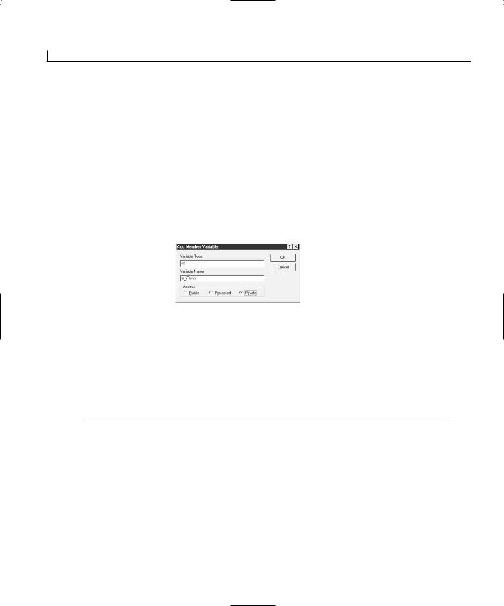
54 |
Day 3 |
Because all the major drawing programs draw lines between each pair of points, what do you need to do to adapt your application so that it also uses this technique? First, you need to keep track of the previous position of the mouse. This means you need to add two variables to the dialog window to maintain the previous X and Y coordinates. You can do this by following these steps:
1. In the workspace pane, select the Class View tab.
2. Select the dialog class—in this case, the CMouseDlg class.
3.Right-click the mouse and select Add Member Variable from the pop-up menu.
4.Enter int as the Variable Type and m_iPrevY as the Variable Name and specify Private for the access in the Add Member Variable dialog, as shown in Figure 3.2.
FIGURE 3.2.
The Add Member
Variable dialog.
5.Click OK to add the variable.
6.Repeat steps 3 through 5, specifying the Variable Name as m_iPrevX to add the second variable.
After you add the variables needed to keep track of the previous mouse position, you can make the necessary modifications to the OnMouseMove function, as shown in Listing 3.2.
LISTING 3.2. THE REVISED OnM ouseM ove FUNCTION.
1:void CMouseDlg::OnMouseMove(UINT nFlags, CPoint point)
2:{
3:// TODO: Add your message handler code here and/or call default
4:
5:///////////////////////
6:// MY CODE STARTS HERE
7:///////////////////////
9:// Check to see if the left mouse button is down
10:if ((nFlags & MK_LBUTTON) == MK_LBUTTON)
11:{
12:// Get the Device Context
13:CClientDC dc(this);
14:
15:// Draw a line from the previous point to the current point
16:dc.MoveTo(m_iPrevX, m_iPrevY);

Integrating the Mouse and Keyboard in Your Application |
55 |
17: dc.LineTo(point.x, point.y); 18:
19:// Save the current point as the previous point
20:m_iPrevX = point.x;
21:m_iPrevY = point.y;
22:}
23:
24:///////////////////////
25:// MY CODE ENDS HERE
26:///////////////////////
28:CDialog::OnMouseMove(nFlags, point);
29:}
Look at the code that draws the line from the previous point to the current point:
dc.MoveTo(m_iPrevX, m_iPrevY);
3
dc.LineTo(point.x, point.y);
You see that you need to move to the first position and then draw a line to the second point. The first step is important because without it, there is no telling where Windows might think the starting position is. If you compile and run your application, it draws a bit better. However, it now has a peculiar behavior. Every time you press the left mouse button to begin drawing some more, your application draws a line from where you ended the last line you drew, as shown in Figure 3.3.
FIGURE 3.3.
The drawing program with a peculiar behavior.
Adding the Finishing Touches
Your application is doing all its drawing on the mouse move event when the left button is held down. Initializing the previous position variables with the position of the mouse when the left button is pressed should correct this application behavior. Let’s try this approach by following these steps:
1.Using the Class Wizard, add a function for the WM_LBUTTONDOWN message on the dialog object.
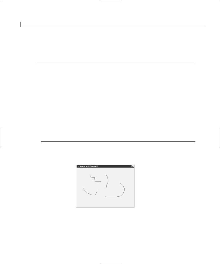
56 |
Day 3 |
2.Edit the OnLButtonDown function that you just created, adding the code in Listing 3.3.
LISTING 3.3. THE OnLButtonDown FUNCTION.
1:void CMouseDlg::OnLButtonDown(UINT nFlags, CPoint point)
2:{
3:// TODO: Add your message handler code here and/or call default
5:///////////////////////
6:// MY CODE STARTS HERE
7:///////////////////////
9:// Set the current point as the starting point
10:m_iPrevX = point.x;
11:m_iPrevY = point.y;
13:///////////////////////
14:// MY CODE ENDS HERE
15:///////////////////////
17:CDialog::OnLButtonDown(nFlags, point);
18:}
When you compile and run your application, you should find that you can draw much like you would expect with a drawing program, as shown in Figure 3.4.
FIGURE 3.4.
The finished drawing program.
Capturing Keyboard Events
Reading keyboard events is similar to reading mouse events. As with the mouse, there are event messages for when a key is pressed and when it is released. These events are listed in Table 3.2.

Integrating the Mouse and Keyboard in Your Application |
57 |
TABLE 3.2. KEYBOARD EVENT MESSAGES.
Message |
Description |
W M _ K E Y D O W N
WM_KEYUP
A key has been pressed down.
A key has been released.
The keyboard obviously has fewer messages than the mouse does. Then again, there are only so many things that you can do with the keyboard. These event messages are available on the dialog window object and are triggered only if there are no enabled controls on the window. Any enabled controls on the window have input focus, so all keyboard events go to them. That’s why you remove all controls from the main dialog for your drawing application.
Changing the Drawing Cursor |
3 |
To get a good idea of how you can use keyboard-related event messages, why don’t you use certain keys to change the mouse cursor in your drawing application? Make the A key change the cursor to the default arrow cursor, which your application starts with. Then you can make B change the cursor to the I-beam and C change the cursor to the hourglass. To get started adding this functionality, follow these steps:
1.Using the Class Wizard, add a function for the W M _ K E Y D O W N message on the dialog object.
2.Edit the OnKeyDown function that you just created, adding the code in Listing 3.4.
LISTING 3.4. THE OnKeyDown FUNCTION.
1:void CMouseDlg::OnKeyDown(UINT nChar, UINT nRepCnt, UINT nFlags)
2:{
3:// TODO: Add your message handler code here and/or call default
5:///////////////////////
6:// MY CODE STARTS HERE
7:///////////////////////
9: |
char lsChar; |
// The current character being pressed |
10: |
HCURSOR lhCursor; |
// The handle to the cursor to be displayed |
11: |
|
|
12:// Convert the key pressed to a character
13:lsChar = char(nChar);
14:
15:// Is the character “A”
16:if (lsChar == ‘A’)
continues
58 |
Day 3 |
LISTING 3.4. CONTINUED
17:{
18:// Load the arrow cursor
19:lhCursor = AfxGetApp()->LoadStandardCursor(IDC_ARROW);
20:// Set the screen cursor
21:SetCursor(lhCursor);
22:}
23:
24:// Is the character “B”
25:if (lsChar == ‘B’)
26:{
27:// Load the I beam cursor
28:lhCursor = AfxGetApp()->LoadStandardCursor(IDC_IBEAM);
29:// Set the screen cursor
30:SetCursor(lhCursor);
31:}
32:
33:// Is the character “C”
34:if (lsChar == ‘C’)
35:{
36:// Load the hourglass cursor
37:lhCursor = AfxGetApp()->LoadStandardCursor(IDC_WAIT);
38:// Set the screen cursor
39:SetCursor(lhCursor);
40:}
41:
42:// Is the character “X”
43:if (lsChar == ‘X’)
44:{
45:// Load the arrow cursor
46:lhCursor = AfxGetApp()->LoadStandardCursor(IDC_ARROW);
47:// Set the screen cursor
48:SetCursor(lhCursor);
49:// Exit the application
50:OnOK();
51:}
52:
53:///////////////////////
54:// MY CODE ENDS HERE
55:///////////////////////
57:CDialog::OnKeyDown(nChar, nRepCnt, nFlags);
58:}
In the function definition, you see three arguments to the OnKeyDown function. The first is the key that was pressed. This argument is the character code of the character, which needs to be converted into a character in the first line of your code. After you convert the
Integrating the Mouse and Keyboard in Your Application |
59 |
character, you can perform straight-ahead comparisons to determine which key was pressed:
void CMouseDlg::OnKeyDown(UINT nChar, UINT nRepCnt, UINT nFlags)
The second argument to the OnKeyDown function is the number of times that the key is pressed. Normally, if the key is pressed and then released, this value is 1. If the key is pressed and held down, however, the repeat count rises for this key. In the end, this value tells you how many times that Windows thinks the key has been pressed.
The third argument to the OnKeyDown function is a combination flag that can be exam- |
|
|
ined to determine whether the Alt key was pressed at the same time as the key or |
|
|
whether the key being pressed is an extended key. This argument does not tell you |
|
|
whether the shift or control keys were pressed. |
|
|
3 |
||
When you determine that a specific key was pressed, then it’s time to change the cursor |
||
to whichever cursor is associated with that key. There are two steps to this process. The |
|
|
first step is to load the cursor into memory. You accomplish this step with the |
|
|
LoadStandardCursor function, which loads one of the standard Windows cursors and |
|
|
returns a handle to the cursor. |
|
Note
A sister function, LoadCursor, can be passed the file or resource name of a custom cursor so that you can create and load your own cursors. If you design your own cursor in the resource editor in Visual C++, you can pass the cursor name as the only argument to the LoadCursor function. For example, if you create your own cursor and name it IDC_MYCURSOR, you can load it with the following line of code:
lhCursor = AfxGetApp()->LoadCursor(IDC_MYCURSOR);
After you load your own cursor, you can set the mouse pointer to your cursor using the SetCursor function, as with a standard cursor.
After the cursor is loaded into memory, the handle to that cursor is passed to the SetCursor function, which switches the cursor to the one the handle points to. If you compile and run your application, you should be able to press one of these keys and get the cursor to change, as in Figure 3.5. However, the moment you move the mouse to do any drawing, the cursor switches back to the default arrow cursor. The following section describes how to make your change stick.
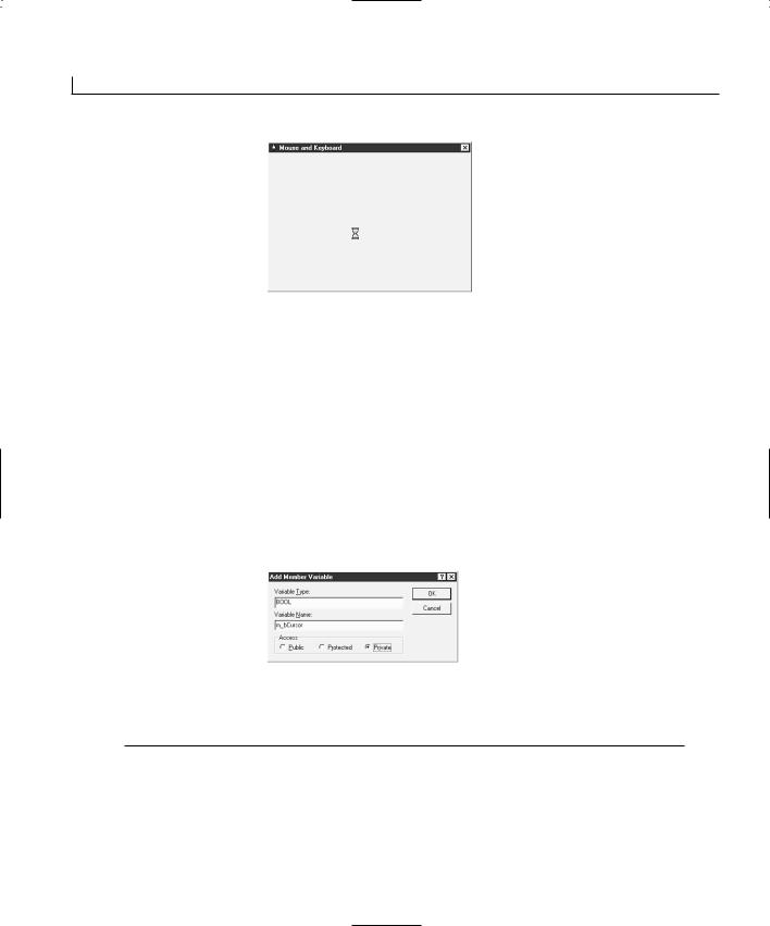
60 |
Day 3 |
FIGURE 3.5.
Changing the cursor with specific keys.
Making the Change Stick
The problem with your drawing program is that the cursor is redrawn every time you move the mouse. There must be some way of turning off this behavior.
Each time the cursor needs to be redrawn—because the mouse has moved, because another window that was in front of your application has gone away, or because of whatever other reason—a WM_SETCURSOR event message is sent to your application. If you override the native behavior of your application on this event, the cursor you set remains unchanged until you change it again. To do this, follow these steps:
1.Add a new variable to the CMouseDlg class, as you did for the previous position variables. This time, declare the type as BOOL and name the variable m_bCursor, as shown in Figure 3.6.
FIGURE 3.6.
Defining a class member variable.
2. Initialize the m_bCursor variable in the OnInitDialog with the code in Listing 3.5.
LISTING 3.5. THE OnInitDialog FUNCTION.
1:BOOL CMouseDlg::OnInitDialog()
2:{
3:CDialog::OnInitDialog();
4:
8:// Set the icon for this dialog. The framework does thisautomatically
Integrating the Mouse and Keyboard in Your Application |
61 |
9:// when the application’s main window is not a dialog
10: |
SetIcon(m_hIcon, TRUE); |
// Set big icon |
11: |
SetIcon(m_hIcon, FALSE); |
// Set small icon |
12: |
|
|
13: |
// TODO: Add extra initialization here |
|
14: |
|
|
15:///////////////////////
16:// MY CODE STARTS HERE
17:///////////////////////
19:// Initialize the cursor to the arrow
20:m_bCursor = FALSE;
21:
22:///////////////////////
23:// MY CODE ENDS HERE
24:///////////////////////
25: |
3 |
|
26:return TRUE; // return TRUE unless you set the focus to acontrol
27:}
3.Alter the OnKeyDown function to set the m_bCursor flag to TRUE when you change the cursor, as in Listing 3.6.
LISTING 3.6. THE OnKeyDown FUNCTION.
1:void CMouseDlg::OnKeyDown(UINT nChar, UINT nRepCnt, UINT nFlags)
2:{
3:// TODO: Add your message handler code here and/or call default
5:///////////////////////
6:// MY CODE STARTS HERE
7:///////////////////////
9: |
char lsChar; |
// The current character being pressed |
10: |
HCURSOR lhCursor; |
// The handle to the cursor to be displayed |
11: |
|
|
12:// Convert the key pressed to a character
13:lsChar = char(nChar);
14:
15:// Is the character “A”
16:if (lsChar == ‘A’)
17:// Load the arrow cursor
18:lhCursor = AfxGetApp()->LoadStandardCursor(IDC_ARROW);
20:// Is the character “B”
21:if (lsChar == ‘B’)
continues
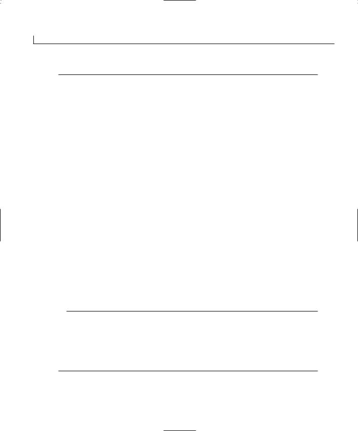
62 |
Day 3 |
LISTING 3.6. CONTINUED
22:// Load the I beam cursor
23:lhCursor = AfxGetApp()->LoadStandardCursor(IDC_IBEAM);
25:// Is the character “C”
26:if (lsChar == ‘C’)
27:// Load the hourglass cursor
28:lhCursor = AfxGetApp()->LoadStandardCursor(IDC_WAIT);
30:// Is the character “X”
31:if (lsChar == ‘X’)
32:{
33:// Load the arrow cursor
34:lhCursor = AfxGetApp()->LoadStandardCursor(IDC_ARROW);
35:// Set the cursor flag
36:m_bCursor = TRUE;
37:// Set the screen cursor
38:SetCursor(lhCursor);
39:// Exit the application
40:OnOK();
41:}
42:else
43:{
44:// Set the cursor flag
45:m_bCursor = TRUE;
46:// Set the screen cursor
47:SetCursor(lhCursor);
48:}
49:
50:///////////////////////
51:// MY CODE ENDS HERE
52:///////////////////////
54:CDialog::OnKeyDown(nChar, nRepCnt, nFlags);
55:}
4.Using the Class Wizard, add a function for the WM_SETCURSOR message on the dialog object.
5.Edit the OnSetCursor function that you just created, adding the code in Listing 3.7.
LISTING 3.7. THE OnSetCursor FUNCTION.
1:BOOL CMouseDlg::OnSetCursor(CWnd* pWnd, UINT nHitTest, UINT message)
2:{
3:// TODO: Add your message handler code here and/or call default
4:
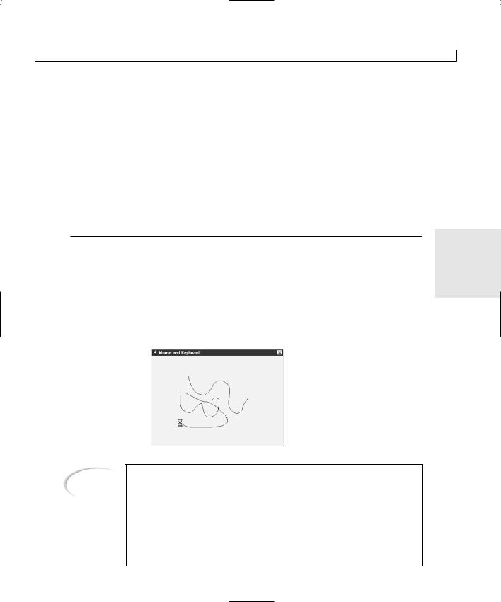
Integrating the Mouse and Keyboard in Your Application |
63 |
5:///////////////////////
6:// MY CODE STARTS HERE
7:///////////////////////
9:// If the cursor has been set, then return TRUE
10:if (m_bCursor)
11:return TRUE;
12:else
13:
14:///////////////////////
15:// MY CODE ENDS HERE
16:///////////////////////
18:return CDialog::OnSetCursor(pWnd, nHitTest, message);
19:}
The OnSetCursor function needs to always return TRUE or else call the ancestor function. |
3 |
The ancestor function resets the cursor and does need to be called when the application first starts. Because of this, you need to initialize your variable to FALSE so that until the user presses a key to change the cursor, the default OnSetCursor processing is executed.
When the user changes the cursor, you want to bypass the default processing and return TRUE instead. This allows the user to draw with whichever cursor has been selected, including the hourglass, as shown in Figure 3.7.
FIGURE 3.7.
Drawing with the hourglass cursor.
Note
The most common cursor change that you are likely to use in your programs is setting the cursor to the hourglass while your program is working on something that might take a while. There are actually two functions available in MFC that you can use to handle this task. The first is BeginWaitCursor, which displays the hourglass cursor for the user. The second function is EndWaitCursor, which restores the cursor to the default cursor. Both of these functions are members of the CCmdTarget class, from which all of the MFC window and control classes are derived.
64 |
Day 3 |
If you have a single function controlling all the processing during which you need to display the hourglass and you don’t need to display the hourglass after the function has finished, an easier way to show the hourglass cursor is to declare a variable of the CWaitCursor class at the beginning of the function. This automatically displays the hourglass cursor for the user. As soon as the program exits the function, the cursor will be restored to the previous cursor.
Summary
In this chapter, you learned about how you can capture mouse event messages and perform some simple processing based upon these events. You used the mouse events to build a simple drawing program that you could use to draw freehand figures on a dialog window.
You also learned how to grab keyboard events and determine which key is being pressed. You used this information to determine which cursor to display for drawing. For this to work, you had to learn about the default cursor drawing in MFC applications and how you could integrate your code with this behavior to make your application behave the way you want it to.
From here, you will learn how to use the Windows timer to trigger events at regular intervals. You will also learn how to use additional dialog windows to get feedback from the user so that you can integrate that feedback into how your application behaves. After that, you will learn how to create menus for your applications.
Q&A
QHow can I change the type of line that I am drawing? I would like to draw a larger line with a different color.
AWhen you use any of the standard device context commands to draw on the screen, you are drawing with what is known as a pen, much like the pen you use to draw on a piece of paper. To draw bigger lines, or different color lines, you need to select a new pen. You can do this by adapting the code in the OnMouseMove function, starting where you get the device context. The following code enables you to draw with a big red pen:
//Get the Device Context CClientDC dc(this);
//Create a new pen
CPen lpen(PS_SOLID, 16, RGB(255, 0, 0));

Integrating the Mouse and Keyboard in Your Application |
65 |
//Use the new pen dc.SelectObject(&lpen);
//Draw a line from the previous point to the current point dc.MoveTo(m_iPrevX, m_iPrevY);
dc.LineTo(point.x, point.y);
QHow can you tell whether the Shift or Ctrl keys are being held down when you receive the WM _ KEYDOWN message?
AYou can call another function, ::GetKeyState, with a specific key code to determine whether that key is being held down. If the return value of the ::GetKeyState function is negative, the key is being held down. If the return value is nonnegative, the key is not being held down. For instance, if you want to determine whether the Shift key is being held down, you can use this code:
if (::GetKeyState(VK_SHIFT) < 0) |
3 |
MessageBox(“Shift key is down!”); |
|
A number of virtual key codes are defined in Windows for all the special keys. |
|
These codes let you look for special keys without worrying about OEM scan codes |
|
or other key sequences. You can use these virtual key codes in the ::GetKeyState |
|
function and pass them to the OnKeyDown function as the nChar argument. Refer to |
|
the Visual C++ documentation for a list of the virtual key codes. |
|
Workshop
The Workshop provides quiz questions to help you solidify your understanding of the material covered and exercises to provide you with experience in using what you’ve learned. The answers to the quiz questions and exercises are provided in Appendix B, “Answers.”
Quiz
1.What are the possible mouse messages that you can add functions for?
2.How can you tell if the left mouse button is down on the WM_MOUSEMOVE event message?
3.How can you prevent the cursor from changing back to the default cursor after you set it to a different one?
Exercises
1. Modify your drawing program so that the left mouse button can draw in red and

66 |
Day 3 |
the right mouse button can draw in blue.
2.Extend the OnKeyDown function to add some of the following standard cursors:
•IDC_CROSS
•IDC_UPARROW
•IDC_SIZEALL
•IDC_SIZENWSE
•IDC_SIZENESW
•IDC_SIZEWE
•IDC_SIZENS
•IDC_NO
•IDC_APPSTARTING
•IDC_HELP
WEEK 1
DAY 4
Working with Timers
You may often find yourself building an application that needs to perform a specific action on a regular basis. The task can be something simple such as displaying the current time in the status bar every second or writing a recovery file every five minutes. Both of these actions are regularly performed by several applications that you probably use on a daily basis. Other actions that you might need to perform include checking specific resources on a regular basis, as a resource monitor or performance monitor does. These examples are just a few of the situations where you want to take advantage of the availability of timers in the Windows operating system.
Today you are going to learn
•How to control and use timers in your Visual C++ applications.
•How to set multiple timers, each with a different recurrence interval.
•How to know which timer has triggered.
•How you can incorporate this important resource into all your Visual C++ applications.

68 |
Day 4 |
Understanding Windows Timers
Windows timers are mechanisms that let you set one or more timers to be triggered at a specific number of milliseconds. If you set a timer to be triggered at a 1,000 millisecond interval, it triggers every second. When a timer triggers, it sends a WM_TIMER message to your application. You can use the Class Wizard to add a function to your application to handle this timer message.
Timer events are placed only in the application event queue if that queue is empty and the application is idle. Windows does not place timer event messages in the application event queue if the application is already busy. If your application has been busy and has missed several timer event messages, Windows places only a single timer message in the event queue. Windows does not send your application all the timer event messages that occurred while your application was busy. It doesn’t matter how many timer messages your application may have missed; Windows still places only a single timer message in your queue.
When you start or stop a timer, you specify a timer ID, which can be any integer value. Your application uses this timer ID to determine which timer event has triggered, as well as to start and stop timers. You’ll get a better idea of how this process works as you build your application for today.
Placing a Clock on Your Application
In the application that you will build today, you will use two timers. The first timer maintains a clock on the window. This timer is always running while the application is running. The second timer is configurable to trigger at whatever interval the user specifies in the dialog. The user can start and stop this timer at will. Let’s get started.
Creating the Project and Application
You will build today’s sample application in three phases. In the first phase, you will add all the controls necessary for the entire application. In the second phase, you will add the first of the two timers. This first timer will control the clock on the application dialog. In the third phase, you will add the second timer, which the user can tune, start, and stop as desired.
To create today’s application, follow these steps:
1.Create a new project, named Timers, using the same AppWizard settings that you’ve used for the past three days. Specify the application title as Timers.
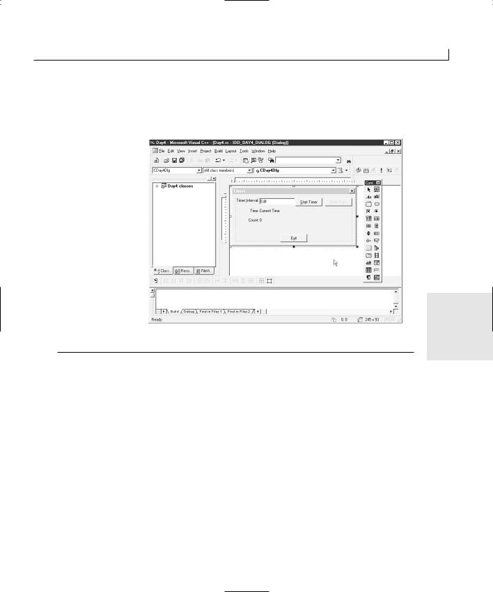
Working with Timers |
69 |
2.Lay out the dialog window as shown in Figure 4.1, using the control properties in Table 4.1. Remember that when you place a control on the window, you can rightclick the mouse to open the control’s properties from the pop-up menu.
FIGURE 4.1.
The Timers application dialog layout.
4
TABLE 4.1. CONTROL PROPERTY SETTINGS.
Object |
Property |
Setting |
Static Text |
ID |
IDC_STATIC |
|
Caption |
Timer &Interval: |
Edit Box |
ID |
IDC_INTERVAL |
Button |
ID |
IDC_STARTTIME |
|
Caption |
&Start Timer |
Button |
ID |
IDC_STOPTIMER |
|
Caption |
S&top Timer |
|
Disabled |
Checked |
Static Text |
ID |
IDC_STATIC |
|
Caption |
Time: |
Static Text |
ID |
IDC_STATICTIME |
|
Caption |
Current Time |
continues
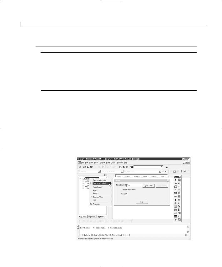
70 |
Day 4 |
TABLE 4.1. CONTINUED
Object |
Property |
Setting |
Static Text |
ID |
|
Caption |
Static Text |
ID |
|
Caption |
Button |
ID |
|
Caption |
IDC_STATIC
Count:
IDC_STATICCOUNT
0
IDC_EXIT
E&xit
3.Set the tab order as you learned on Day 2, “Using Controls in Your Application.”
4.Add code to the Exit button to close the application, as you did on Day 2.
Adding the Timer IDs
Because you will be using two timers in this application, you should add two IDs to your application to represent the two timer IDs. This can be done by following these steps:
1.On the Resource View tab in the workspace pane, right-click the mouse over the Timers resources folder at the top of the resource tree. Select Resource Symbols from the pop-up menu, as in Figure 4.2.
FIGURE 4.2.
The Resource pop-up menu.
2. On the Resource Symbols dialog, click the New button.
Working with Timers |
71 |
3.On the New Symbol dialog, enter ID_CLOCK_TIMER as the symbol name and 1 as the value, as shown in Figure 4.3.
FIGURE 4.3.
Adding a new resource symbol.
4
4.Repeat steps 2 and 3, specifying ID_COUNT_TIMER as the symbol name and 2 as the value.
5.Click the Close button to close the Resource Symbols dialog. The two timer IDs are now in your application and ready for use.
Starting the Clock Timer
To start the clock timer, you need to edit the OnInitDialog function, as you did in the previous two days. Add the new code in Listing 4.1.
LISTING 4.1. THE OnInitDialog FUNCTION.
1:BOOL CTimersDlg::OnInitDialog()
2:{
3:CDialog::OnInitDialog();
7:// TODO: Add extra initialization here
9:///////////////////////
continues
72 |
Day 4 |
LISTING 4.1. CONTINUED
10:// MY CODE STARTS HERE
11:///////////////////////
13:// Start the clock timer
14:SetTimer(ID_CLOCK_TIMER, 1000, NULL);
16:///////////////////////
17:// MY CODE ENDS HERE
18:///////////////////////
20:return TRUE; // return TRUE unless you set the focus to acontrol
21:}.
In this listing, you started the clock timer with the SetTimer function. The first argument that you passed to the SetTimer function is the ID for the clock timer. The second argument is how often you want to trigger the event. In this case, the clock timer event is triggered every 1,000 milliseconds, or about every second. The third argument is the address of an optional callback function that you can specify to bypass the WM_TIMER event. If you pass NULL for this argument, the WM_TIMER event is placed in the application message queue.
Note
A callback function is a function you create that is called directly by the Windows operating system. Callback functions have specific argument definitions, depending on which subsystem calls the function and why. After you get past the function definition, however, you can do whatever you want or need to do in the function.
A callback function works by passing the address of the function as an argument to a Windows function that accepts callback functions as arguments. When you pass the function address to Windows, your function is called directly every time the circumstances occur that require Windows to call the callback function.
Handling the Clock Timer Event
Now that you’ve started a timer, you need to add the code to handle the timer event message. You can do this by following these steps:
1. Using the Class Wizard, add a variable to the IDC_STATICTIME control of type
CString named m_sTime.
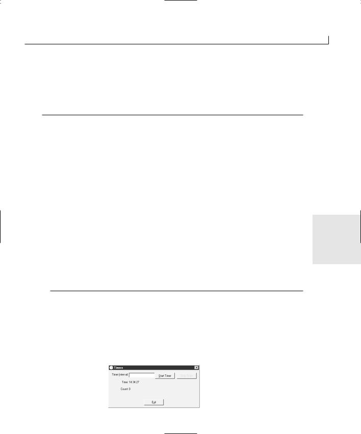
Working with Timers |
73 |
2. Using the Class Wizard, add a function to handle the WM_TIMER message for the
CTimersDlg object.
3. Edit the OnTimer function, adding the code in Listing 4.2.
LISTING 4.2. THE OnTimer FUNCTION.
1:void CTimersDlg::OnTimer(UINT nIDEvent)
2:{
3:// TODO: Add your message handler code here and/or call default
5:///////////////////////
6:// MY CODE STARTS HERE
7:///////////////////////
9:// Get the current time
10: CTime curTime = CTime::GetCurrentTime(); 11:
12:// Display the current time
13:m_sTime.Format(“%d:%d:%d”, curTime.GetHour(),
14:curTime.GetMinute(),
15:curTime.GetSecond());
16:
17: // Update the dialog 4 18: UpdateData(FALSE);
19:
20:///////////////////////
21:// MY CODE ENDS HERE
22:///////////////////////
24:CDialog::OnTimer(nIDEvent);
25:}
In this listing, you declare an instance of the CTime class, initializing it to the current system time. The next thing that you do is set the m_sTime string to the current time, using the Format method to format the time in the familiar HH:MM:SS format. Finally, you update the dialog window with the current time. If you compile and run your application now, you should see a clock running in the middle of your dialog window, as in Figure 4.4.
FIGURE 4.4.
A running clock on your application
dialog.
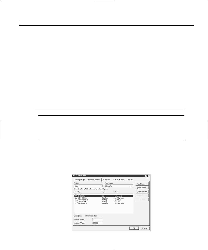
74 |
Day 4 |
Adding a Second Timer to Your Application
As you have seen, adding a single timer to an application is a pretty simple task. All it takes is calling the SetTimer function and then placing the timer code in the OnTimer function. However, sometimes you need more than one timer running simultaneously in the same application. Then things get a little bit more involved.
Adding the Application Variables
Before you add the second timer to your application, you need to add a few variables to the controls. With the clock timer, you needed only a single variable for updating the clock display. Now you need to add a few other variables for the other controls, as listed in Table 4.2.
TABLE 4.2. CONTROL VARIABLES.
Object |
Name |
Category |
Type |
IDC_STATICCOUNT |
m_sCount |
IDC_INTERVAL |
m_iInterval |
IDC_STARTTIME |
m_cStartTime |
IDC_STOPTIMER |
m_cStopTime |
Value |
CString |
Value |
int |
Control |
CButton |
Control |
CButton |
After you add all the variables using the Class Wizard, follow these steps:
1.Using the Class Wizard, select the m_iInterval variable and specify a Minimum Value of 1 and a Maximum Value of 100000 in the two edit boxes below the list of variables, as shown in Figure 4.5.
FIGURE 4.5.
Specifying a range for a variable.
Working with Timers |
75 |
2.On the Class View tab in the workspace pane, add a member variable to the CTimersDlg class as you learned yesterday. Specify the variable type as int, the variable name as m_iCount, and the access as Private.
3.Using the Class Wizard, add a function on the EN_CHANGE event message for the IDC_INTERVAL control ID (the edit box). Edit the function and add the code in Listing 4.3.
LISTING 4.3. THE OnChangeInterval FUNCTION.
1:void CTimersDlg::OnChangeInterval()
2:{
3:// TODO: If this is a RICHEDIT control, the control will not
4:// send this notification unless you override the
CDialog::OnInitialUpdate()
5:// function and call CRichEditCrtl().SetEventMask()
6:// with the EN_CHANGE flag ORed into the mask.
8: |
// TODO: Add your control notification handler code here |
|
9: |
|
|
10: |
/////////////////////// |
|
11: |
// MY CODE STARTS HERE |
4 |
12: |
/////////////////////// |
|
13: |
|
|
14:// Update the variables
15:UpdateData(TRUE);
17:///////////////////////
18:// MY CODE ENDS HERE
19:///////////////////////
20:}
When you specify a value range for the timer interval variable, Visual C++ automatically prompts the user, stating the available value range if the user enters a value outside of the specified range. This prompt is triggered by the UpdateData function call in the OnChangeInterval function. The last variable that was added through the workspace pane is used as the actual counter, which is incremented with each timer event.
Starting and Stopping the Counting Timer
To make your second timer operational, you need to
• Initialize the m_iInterval variable.
• |
Start the timer when the IDC_STARTTIME button is clicked. |
• |
Increment the m_iCount variable and update the dialog on each timer event. |
• |
Stop the timer when the IDC_STOPTIMER button is clicked. |
76 |
Day 4 |
To implement this additional functionality, perform the following steps:
1. Edit the OnInitDialog function, updating the code as in Listing 4.4.
LISTING 4.4. THE UPDATED OnInitDialog FUNCTION.
1:BOOL CTimersDlg::OnInitDialog()
2:{
3:CDialog::OnInitDialog();
7:// TODO: Add extra initialization here
9:///////////////////////
10:// MY CODE STARTS HERE
11:///////////////////////
13:// Initialize the counter interval
14:m_iInterval = 100;
15:
16:// Update the dialog
17:UpdateData(FALSE);
19:// Start the clock timer
20:SetTimer(ID_CLOCK_TIMER, 1000, NULL);
22:///////////////////////
23:// MY CODE ENDS HERE
24:///////////////////////
26:return TRUE; // return TRUE unless you set the focus to acontrol
27:}
2.Using the Class Wizard, add a function to the BN_CLICKED message on the IDC_STARTTIME button. Edit the OnStarttime function as in Listing 4.5.
LISTING 4.5. THE OnStarttime FUNCTION.
1:void CTimersDlg::OnStarttime()
2:{
3:// TODO: Add your control notification handler code here
5:///////////////////////
6:// MY CODE STARTS HERE
7:///////////////////////
Working with Timers |
77 |
9:// Update the variables
10: UpdateData(TRUE); 11:
12:// Initialize the count
13:m_iCount = 0;
14:// Format the count for displaying
15:m_sCount.Format(“%d”, m_iCount);
17:// Update the dialog
18:UpdateData(FALSE);
19:// Start the timer
20:SetTimer(ID_COUNT_TIMER, m_iInterval, NULL);
22:///////////////////////
23:// MY CODE ENDS HERE
24:///////////////////////
25:}
3.Using the Class Wizard, add a function to the BN_CLICKED message on the IDC_STOPTIMER button. Edit the OnStoptimer function as in Listing 4.6.
LISTING 4.6. THE OnStoptimer FUNCTION. |
4 |
|
1:void CTimersDlg::OnStoptimer()
2:{
3:// TODO: Add your control notification handler code here
5:///////////////////////
6:// MY CODE STARTS HERE
7:///////////////////////
9:// Stop the timer
10: KillTimer(ID_COUNT_TIMER); 11:
12:///////////////////////
13:// MY CODE ENDS HERE
14:///////////////////////
15:}
4. Edit the OnTimer function, updating the code as in Listing 4.7.
LISTING 4.7. THE UPDATED OnTimer FUNCTION.
1:void CTimersDlg::OnTimer(UINT nIDEvent)
2:{
3:// TODO: Add your message handler code here and/or call default
continues
78 |
Day 4 |
LISTING 4.7. CONTINUED
4:
5:///////////////////////
6:// MY CODE STARTS HERE
7:///////////////////////
9:// Get the current time
10: CTime curTime = CTime::GetCurrentTime(); 11:
12:// Which timer triggered this event?
13:switch (nIDEvent)
14:{
15:// The clock timer?
16:case ID_CLOCK_TIMER:
17:// Display the current time
18:m_sTime.Format(“%d:%d:%d”, curTime.GetHour(),
19:curTime.GetMinute(),
20:curTime.GetSecond());
21:break;
22:// The count timer?
23:case ID_COUNT_TIMER:
24:// Increment the count
25:m_iCount++;
26:// Format and display the count
27:m_sCount.Format(“%d”, m_iCount);
28:break;
29:}
30:
31:// Update the dialog
32:UpdateData(FALSE);
34:///////////////////////
35:// MY CODE ENDS HERE
36:///////////////////////
38:CDialog::OnTimer(nIDEvent);
39:}
In the OnInitDialog function, you added the initialization of the m_iInterval variable, starting it at 100. This initialization is reflected on the dialog window by calling the
UpdateData function.
In the OnStarttime function, you first synchronize the variables with the control values, allowing you to get the current setting of the m_iInterval variable. Next, you initialize the m_iCount variable, setting it to 0, and then format the value in the m_sCount CString variable, which is updated in the dialog window. The last thing that you do is to start the timer, specifying the ID_COUNT_TIMER ID and using the interval from the m_iInterval variable.
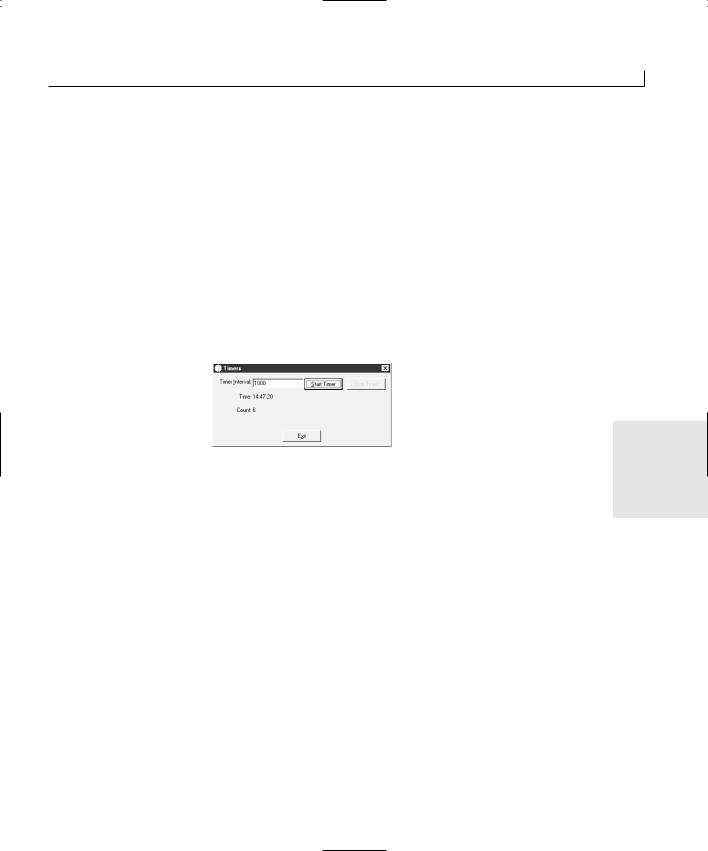
Working with Timers |
79 |
In the OnStoptimer function, all you really need to do is stop the timer. You do this by calling the KillTimer function, passing the timer ID as the only argument.
It is in the OnTimer function that things begin to get interesting. Here, you still see the code for handling the clock timer event. To add the functionality for the counter timer, you need to determine which timer has triggered this function. The only argument to the OnTimer function just happens to be the timer ID. You can use this ID in a switch statement to determine which timer has called this function and to control which set of code is executed. The clock timer code is still the same as it was in Listing 4.2. The counter timer code is placed into its spot in the switch statement, incrementing the counter and then updating the m_sCount variable with the new value. You can compile and run your application at this point, and you can specify a timer interval and start the timer running, as in Figure 4.6.
FIGURE 4.6.
A running counter on your application dialog.
4
Enabling the Stop Button
If you run your application, you’ll find that it works well except for one small problem. When you start your second timer, you can’t stop it. When you were specifying all the properties of the controls, you disabled the Stop Timer button. Before you can stop the timer, you need to enable this button.
What makes the most sense is enabling the stop button and disabling the start button once the timer starts. Then you reverse the situation when the timer stops again. You can do this in the same way you enabled and disabled controls on Day 2, or you can modify your approach just a little.
Remember that when you added variables to the controls, you added variables to the start and stop buttons. These were not normal variables, but control variables. Instead of getting a pointer to these controls using their IDs, you can work directly with the control variables. Try that now by updating the OnStarttime and OnStoptimer functions as in Listing 4.8.

80 |
Day 4 |
LISTING 4.8. THE REVISED OnStarttime AND OnStoptimer FUNCTIONS.
1:void CTimersDlg::OnStarttime()
2:{
3:// TODO: Add your control notification handler code here
5:///////////////////////
6:// MY CODE STARTS HERE
7:///////////////////////
9:// Update the variables
10: UpdateData(TRUE); 11:
12:// Initialize the count
13:m_iCount = 0;
14:// Format the count for displaying
15:m_sCount.Format(“%d”, m_iCount);
17:// Update the dialog
18:UpdateData(FALSE);
19:// Start the timer
20:SetTimer(ID_COUNT_TIMER, m_iInterval, NULL);
22:// Enable the Stop Timer button
23:m_cStopTime.EnableWindow(TRUE);
24:// Disable the Start Timer button
25:m_cStartTime.EnableWindow(FALSE);
27:///////////////////////
28:// MY CODE ENDS HERE
29:///////////////////////
30:}
31:
32:void CTimersDlg::OnStoptimer()
33:{
34:// TODO: Add your control notification handler code here
36:///////////////////////
37:// MY CODE STARTS HERE
38:///////////////////////
40:// Stop the timer
41:KillTimer(ID_COUNT_TIMER);
43:// Disable the Stop Timer button
44:m_cStopTime.EnableWindow(FALSE);
45:// Enable the Start Timer button
46:m_cStartTime.EnableWindow(TRUE);
48:///////////////////////
49:// MY CODE ENDS HERE
Working with Timers |
81 |
50:///////////////////////
51:}
Now when you compile and run your application, it looks more like Figure 4.7, where you can start and stop the counter timer. This enables you to play with the timer interval, putting in a variety of time intervals and observing the difference, with the clock ticking above the counter for reference.
FIGURE 4.7.
The finished application.
Summary
Today you learned how to use the timers built into the Windows operating system to trig- |
|
ger your application at various time intervals that you can control. You learned how to |
4 |
use multiple timers in the same application, running them simultaneously and triggering |
|
different actions. |
|
In the coming days, you’ll learn how to use additional dialog windows to get feedback |
|
from the user so that you can integrate that feedback into how your application behaves. |
|
After that, you will learn how to a create menus for your applications. Then you will |
|
learn how you can work with text and fonts in your applications. |
|
Q&A
Q What is the interval range that I can set for timers in my applications?
AThe available range that you can set for timers in your applications is around 55 milliseconds on the short end to 232 - 1 milliseconds, or around 49 1/2 days, on the
long end.
Q How many timers can I have running at the same time in my application?
AThat depends. There are a limited number of timers available to all applications in the Windows operating system. Although the number that is available should be more than sufficient for all running applications using no more than a handful of timers, if an application goes overboard and begins hogging the timers, the operating system may run out. It could be your application that is denied the use of some timers, or it could be other applications that don’t have any to use. As a general

82 |
Day 4 |
rule, if you use more than two or three timers at the same time, you might want to reconsider your application design and determine if there is another way to design and build your application so that it can work with fewer timers.
QIs there any way to trigger my application to perform some work when it is idle, instead of using a timer to trigger the work when I think my app might be idle?
AYes, there is. All Windows applications have an OnIdle function that can be used to trigger idle processing. OnIdle is discussed later on Day 18, “Doing Multiple Tasks at One Time—Multitasking.”
Workshop
The Workshop provides quiz questions to help you solidify your understanding of the material covered and exercises to provide you with experience in using what you’ve learned. The answers to the quiz questions and exercises are provided in Appendix B, “Answers.”
Quiz
1.What did you accomplish by adding the two timer IDs to the resource symbols?
2.What is another way to add these two IDs to the application?
3.How can you tell two timers apart in the OnTimer function?
4.How many timer events does your application receive if the timer is set for one second and your application has been busy for one minute, preventing it from receiving any timer event messages?
Exercise
Update your application so that when the counter timer is started, the clock timer is reset to run at the same interval as the counter timer. When the counter timer is stopped, return the clock timer to a one-second interval.

WEEK 1
DAY 5
Getting User Feedback— Adding Dialog Boxes to Your Application
With most applications that you might use, there are numerous situations where the application asks you for information—how you want the application configured or whether you want to save your work before exiting, for example. In most of these situations, the application opens a new window to ask these questions. These windows are called dialog windows.
Dialog windows typically have one or more controls and some text explaining what information the program needs from you. Dialog windows typically do not have a large blank work area, as you find in the main windows of a word processor or a programming editor. All the applications that you have built in the preceding days have been dialog windows, and your projects will continue to be dialog windows for the next few days.
All the dialogs that you have created up to now have been single window dialog applications. Today you are going to learn

84 |
Day 5 |
•How to use dialog windows in a more flexible way.
•How to call other dialog windows and take the information entered by the user on these windows back to the main application window for use in the application.
•How to use both standard dialogs, such as the message boxes you used in previous days and custom dialogs that you have created.
Using Pre-existing (or System) Dialog
Windows
The Windows operating system provides a number of pre-existing dialog windows. Simple dialog windows, also known as message boxes, present the user with a message and provide one to three buttons to click. More complex dialogs, such as the File Open, Save, or Print dialogs, are also provided with Windows. These system (or common) dialogs are created and used with a combination of a variable declaration of a C++ class and a series of interactions with the class instance.
Using Message Boxes
As you learned in the previous days, using message boxes is as simple as making a single function call, passing the message text as the only argument. This results in a message box that displays the message to the user with an icon and gives the user one button to click to acknowledge the message. As you probably know from using other Windows software, you have a whole range of other message box possibilities with various button combinations and various icons that can be displayed.
The MessageBox Function
As you have seen in previous days, the MessageBox function can be passed one or two arguments. The first argument is the message to be displayed to the user. The second argument, which is completely optional, is displayed in the title bar on the message box. You can use a third argument, which is also optional, to specify the buttons to be presented to the user and the icon to be displayed beside the message. In addition to this third argument, the MessageBox function returns a result value that indicates which button was clicked by the user. Through the combination of the third argument and the return value, the MessageBox function can provide a whole range of functionality in your Visual C++ applications.
Getting User Feedback—Adding Dialog Boxes to Your Application |
85 |
Note
If you use the third argument to the MessageBox function to specify the buttons or the icon to be presented to the user, the second argument (the message box title) is no longer optional. You must provide a value for the title bar of the message box.
The button combinations that you can use in the MessageBox function are limited. You do not have the freedom to make up your own button combination. If you get to the point where you need to make up your own, you have to create a custom dialog window that looks like a message box. The button combinations that you can use are listed in Table 5.1.
TABLE 5.1. M ESSAGEBOX BUTTON COMBINATION IDS.
ID |
Buttons |
MB_ABORTRETRYIGNORE
MB_OK
MB_OKCANCEL
MB_RETRYCANCEL
MB_YESNO
MB_YESNOCANCEL
Abort, Retry, Ignore
OK
OK, Cancel
Retry, Cancel
Yes, No
Yes, No, Cancel
To specify the icon to be displayed, you can add the icon ID to the button combination
ID. The icons that are available are listed in Table 5.2. If you want to specify either the 5 icon or the button combination, and you want to use the default for the other, you can
just specify the one ID that you want to use.
TABLE 5.2. M ESSAGEBOX ICON IDS.
ID |
Icon |
MB_ICONINFORMATION
MB_ICONQUESTION
MB_ICONSTOP
MB_ICONEXCLAMATION
Informational icon
Question mark icon
Stop sign icon
Exclamation mark icon
When you do specify a button combination, you want to capture the return value so that you can determine which button the user clicked. The return value is defined as an integer data type; the return value IDs are listed in Table 5.3.

86 |
Day 5 |
TABLE 5.3. M ESSAGEBOX RETURN VALUE IDS.
ID |
Button Clicked |
IDABORT |
Abort |
IDRETRY |
Retry |
IDIGNORE |
Ignore |
IDYES |
Yes |
IDNO |
No |
IDOK |
OK |
IDCANCEL |
Cancel |
|
|
Creating a Dialog Application
To get a good understanding of how you can use the MessageBox function in your applications to get information from the user, you will build a simple application that uses the MessageBox function in a couple of different ways. Your application will have two separate buttons that call two different versions of the MessageBox function so that you can see the differences and similarities between the various options of the function. Later in the day, you will add a standard File Open dialog so that you can see how the standard dialogs can be used to allow the user to specify a filename or perform other standard functions. Finally, you will create a custom dialog that allows the user to enter a few different types of values, and you will see how you can read these values from the main application dialog after the user has closed the custom dialog.
To start this application, follow these steps:
1.Create a new MFC AppWizard workspace project, naming it Dialogs.
2.Choose the same settings as for the previous days’ applications, giving the application a title of Dialogs.
3.Lay out the main application dialog as shown in Figure 5.1 using the properties in Table 5.4.
TABLE 5.4. CONTROL PROPERTY SETTINGS.
Object |
Property |
Setting |
Command Button |
ID |
|
Caption |
Command Button |
ID |
|
Caption |
IDC_YESNOCANCEL
&Yes, No, Cancel
IDC_ABORTRETRYIGNORE
&Abort, Retry, Ignore
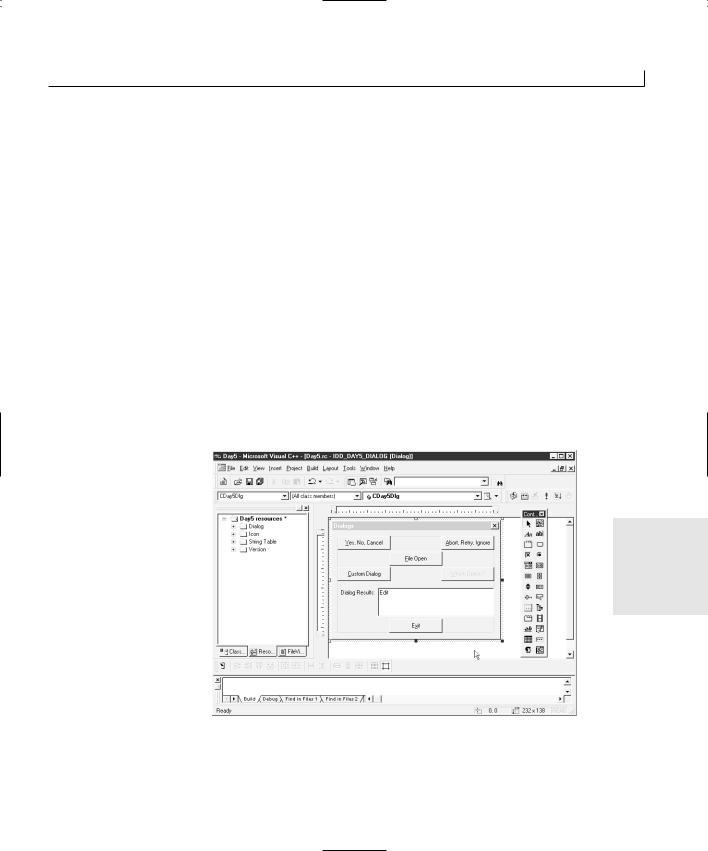
Getting User Feedback—Adding Dialog Boxes to Your Application |
87 |
Object |
Property |
Setting |
|
Command Button |
ID |
IDC_FILEOPEN |
|
|
Caption |
&File Open |
|
Command Button |
ID |
IDC_BCUSTOMDIALOG |
|
|
Caption |
&Custom Dialog |
|
Command Button |
ID |
IDC_BWHICHOPTION |
|
|
Caption |
&Which Option? |
|
|
Disabled |
Checked |
|
Command Button |
ID |
IDC_EXIT |
|
|
Caption |
E&xit |
|
Static Text |
ID |
IDC_STATIC |
|
|
Caption |
Dialog Results: |
|
Edit Box |
ID |
IDC_RESULTS |
|
|
Multiline |
Checked |
|
|
Auto Vscroll |
Checked |
|
|
|
|
|
FIGURE 5.1.
The application main dialog layout.
5
4. Using the Class Wizard, attach variables to the controls as listed in Table 5.5.

88 |
Day 5 |
TABLE 5.5. CONTROL VARIABLES.
Object |
Name |
Category |
Type |
IDC_RESULTS |
m_sResults |
IDC_BWHICHOPTION m_cWhichOption
Value |
CString |
Control |
CButton |
5.Using the Class Wizard, attach code to the Exit button to close the application, as on previous days.
Coding the Message Box Dialogs
For the first command button (the Yes, No, Cancel button), create a function on the clicked event using the Class Wizard, just as you did on previous days. Edit the function on this button, adding the code in Listing 5.1.
LISTING 5.1. THE OnYesnocancel FUNCTIONS.
1:void CDialogsDlg::OnYesnocancel()
2:{
3:// TODO: Add your control notification handler code here
5:///////////////////////
6:// MY CODE STARTS HERE
7:///////////////////////
9: int iResults; // This variable will capture the button selection 10:
11:// Ask the user
12:iResults = MessageBox(“Press the Yes, No, or Cancel button”,
13:“Yes, No, Cancel Dialog”,
14:MB_YESNOCANCEL | MB_ICONINFORMATION);
15:
16:// Determine which button the user clicked
17:// Give the user a message showing which button was clicked
18:switch (iResults)
19:{
20:case IDYES: // The Yes button?
21:m_sResults = “Yes! Yes! Yes!”;
22:break;
23:case IDNO: // The No button?
24:m_sResults = “No, no, no, no, no.”;
25:break;
26:case IDCANCEL: // The Cancel button?
27:m_sResults = “Sorry, canceled.”;
28:break;
29:}
30:
31:// Update the dialog
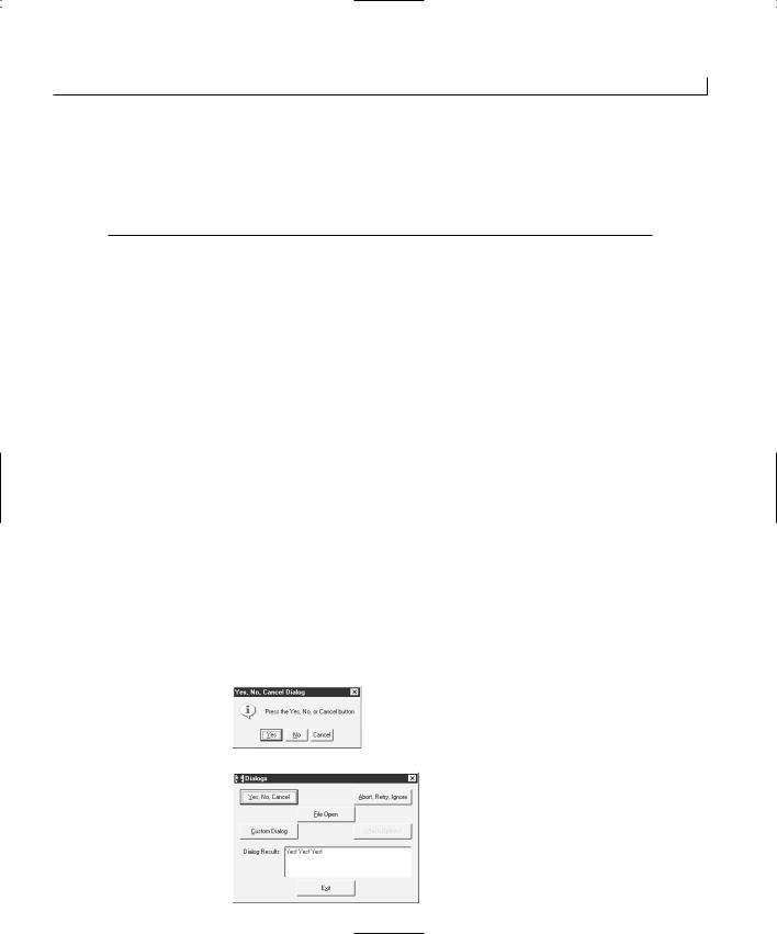
Getting User Feedback—Adding Dialog Boxes to Your Application |
89 |
32: |
UpdateData(FALSE); |
33: |
|
34: |
/////////////////////// |
35: |
// MY CODE ENDS HERE |
36: |
/////////////////////// |
37: } |
|
If you compile and run your application, you can see how selecting the different buttons on the message box can determine the next course of action in your application. If you add a function to the clicked event of the Abort, Retry, Ignore button using the Class Wizard and enter the same code as in Listing 5.1, substituting the MB_ABORTRETRYIGNORE and MB_ICONQUESTION values and changing the prompts and messages, you can see how this other button combination can be used in the same way.
Both of these control event functions are virtually the same. In each function, there is an integer variable declared to capture the return value from the MessageBox function. Next, the MessageBox function is called with a message to be displayed to the user, a title for the message box, and a combination of a button combination ID and an icon ID.
When the return value is captured from the MessageBox function, that value is passed |
|
|
through a switch statement to determine which value was returned. A message is dis- |
|
|
played to the user to indicate which button was clicked on the message box. You can just |
|
|
as easily use one or two if statements to control the program execution based on the |
|
|
user’s selection, but the return value being an integer lends itself to using a switch |
|
|
statement. |
|
|
5 |
||
If you compile and run your application at this point, you can click either of the top two |
||
buttons and see a message box, as in Figure 5.2. When you click one of the message box |
|
|
buttons, you see a message in the edit box on the main dialog, indicating which button |
|
|
you selected, as in Figure 5.3. |
|
|
|
|
FIGURE 5.2.
The MessageBox with
three choices.
FIGURE 5.3.
A message is displayed based on which button
was clicked.

90 |
Day 5 |
Using Common Dialogs
Using common dialogs is not quite as simple and easy as using the MessageBox function, but it’s still quite easy. The Microsoft Foundation Classes (MFC) provides several C++ classes for common Windows dialogs. These classes are listed in Table 5.6.
TABLE 5.6. COMMON DIALOG CLASSES.
Class |
Dialog Type |
CFileDialog |
File selection |
CFontDialog |
Font selection |
CColorDialog |
Color selection |
CPageSetupDialog |
Page setup for printing |
CPrintDialog |
Printing |
CFindReplaceDialog |
Find and Replace |
|
|
The common dialogs encapsulated in these classes are the standard dialogs that you use every day in most Windows applications to open and save files, configure printing options, print, perform find and replace on documents, and so on. In addition to these choices, a series of OLE common dialog classes provide several common functions to OLE or ActiveX components and applications.
All these dialogs are used in the same manner, although the individual properties and class functions vary according to the dialog functionality. To use one of these dialogs, you must follow these steps:
1.Declare a variable of the class type.
2.Set any properties that need to be configured before displaying the dialog to the user.
3.Call the DoModal method of the class to display the dialog to the user.
4.Capture the return value of the DoModal method to determine whether the user clicked the OK or Cancel button.
5.If the user clicks the OK button, read any properties that the user may have set when using the dialog.
To better understand how this works, you’ll add the CFileDialog class to your application. To do this, add a function to the clicked message on the File Open button using the Class Wizard. Edit this function, adding the code in Listing 5.2.
Getting User Feedback—Adding Dialog Boxes to Your Application |
91 |
LISTING 5.2. THE OnFileopen FUNCTION.
1:void CDialogsDlg::OnFileopen()
2:{
3:// TODO: Add your control notification handler code here
5:///////////////////////
6:// MY CODE STARTS HERE
7:///////////////////////
9: CFileDialog m_ldFile(TRUE); 10:
11:// Show the File open dialog and capture the result
12:if (m_ldFile.DoModal() == IDOK)
13:{
14:// Get the filename selected
15:m_sResults = m_ldFile.GetFileName();
16:// Update the dialog
17:UpdateData(FALSE);
18:}
19:
20:///////////////////////
21:// MY CODE ENDS HERE
22:///////////////////////
23:}
In this code, the first thing that you do is declare an instance of the CFileDialog class. This instance is passed TRUE as an argument to the class constructor. This tells the class that it is a File Open dialog. If you pass it FALSE, it displays as a File Save dialog. There’s no
real functional difference between these two, only a visual difference. You can pass many 5 more arguments to the constructor, specifying the file extensions to show, the default
starting file and location, and filters to use when displaying the files. All the rest of these constructor arguments have default values, so you don’t have to supply any of them.
After creating the instance of the File Open dialog, you call its DoModal function. This is a member function of the CDialog ancestor class, and it is available in all dialog windows. The DoModal function displays the File Open dialog to the user, as shown in Figure 5.4.
The return value of the DoModal function is examined to determine which button the user clicked. If the user clicks the Open button, the IDOK value is returned, as with the MessageBox function. This is how you can determine whether your application needs to take any action on what the user selected with the dialog window.
There are two modes in which a dialog window can be displayed to the
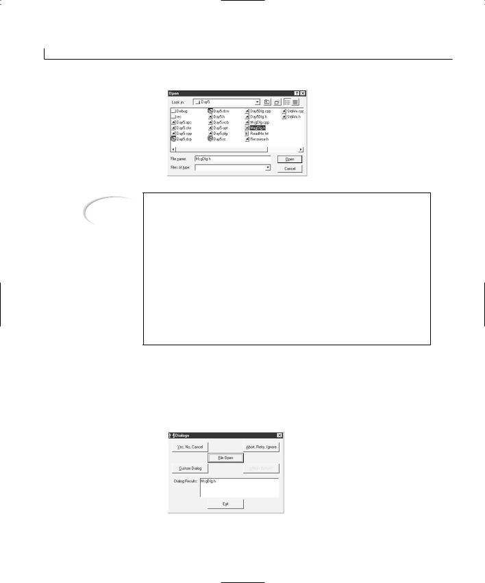
92 |
Day 5 |
FIGURE 5.4.
The File Open dialog.
Note
user. The first is as a modal window. A modal window halts all other user interaction while it is displayed. The user cannot do anything else in the application until the dialog is closed. A good example of a modal dialog window is a message box where the user cannot continue working with the application until she clicks one of the buttons on the message box.
The second mode in which a dialog window can be displayed to the user is as a modeless window. A modeless window can be open while the user is doing something else in the application, and it doesn’t prevent the user from performing other tasks while the dialog is visible. Good examples of a modeless dialog window are the Find and Find and Replace dialogs in Microsoft Word. These dialog windows can be open and displayed on the screen while you are still editing the document that you are searching.
To display the name of the file selected, you set the m_sResults variable to the return value from the GetFileName method of the CFileDialog class. This method returns only the filename without the directory path or drive name, as shown in Figure 5.5. You can use other class methods for getting the directory path (GetPathName) or file extension (GetFileExt).
FIGURE 5.5.
Displaying the selected filename.
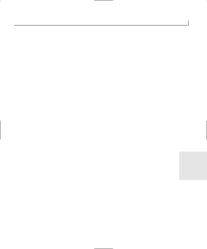
Getting User Feedback—Adding Dialog Boxes to Your Application |
93 |
Creating Your Own Dialog Windows
Now you have an understanding of using standard dialogs. What if you need to create a custom dialog for your application? This task is fairly simple to do because it is mostly a combination of the process that you have already used to create and use the main dialog windows in all your applications and the methods you employed to use the common dialogs. You have to work through a few additional steps, but they are few and you should be comfortable with them soon.
Creating the Dialog Window
For the custom dialog that you will add to your application, you will provide the user with a edit box in which to enter some text and a group of radio buttons from which the user can select one. When the user clicks the OK button, your application will display the text entered by the user in the display area of the main application dialog window. There is another button that the user can, can click to display which one of the radio buttons was selected. This exercise enables you to see how you can use custom dialog windows to gather information from the user and how you can read the user’s selections after the dialog window is closed.
To create a custom dialog for your application, you need to
• |
Add another dialog to your application resources. |
|
• |
Design the dialog window layout. |
|
• |
Declare the base class from which the dialog will be inherited. |
|
• |
Attach variables to the controls on the dialog. |
5 |
After doing these things, your custom dialog will be ready for your application. To accomplish these tasks, follow these steps:
1.Select the Resource View tab in the project workspace pane.
2.Right-click the Dialogs folder, and select Insert Dialog from the pop-up menu.
3.Right-click the new dialog in the resource tree view, and select Properties from the pop-up menu.
4.Change the object ID for the new dialog to IDD_MESSAGEDLG.
5.When editing the new dialog window, do not delete the OK and Cancel buttons. Move them to the location shown in Figure 5.6.
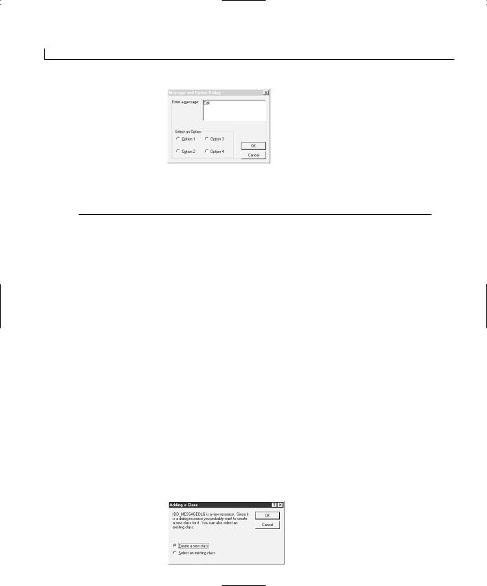
94 |
Day 5 |
FIGURE 5.6.
The custom dialog window layout.
6. Design the rest of the window using the object properties in Table 5.7.
TABLE 5.7. THE CUSTOM DIALOG CONTROL PROPERTY SETTINGS.
Object |
Property |
Setting |
Static Text |
ID |
IDC_STATIC |
|
Caption |
Enter a &message: |
Edit Box |
ID |
IDC_MESSAGE |
|
Multiline |
Checked |
|
Auto Vscroll |
Checked |
Group Box |
ID |
STATIC |
|
Caption |
Select an Option |
Radio Button |
ID |
IDC_OPTION1 |
|
Caption |
&Option 1 |
|
Group |
Checked |
Radio Button |
ID |
IDC_OPTION2 |
|
Caption |
O&ption 2 |
Radio Button |
ID |
IDC_OPTION3 |
|
Caption |
Op&tion 3 |
Radio Button |
ID |
IDC_OPTION4 |
|
Caption |
Opt&ion 4 |
|
|
|
7.After you design the dialog, open the Class Wizard. You see the dialog in Figure 5.7.
FIGURE 5.7.
The Adding a Class
dialog.
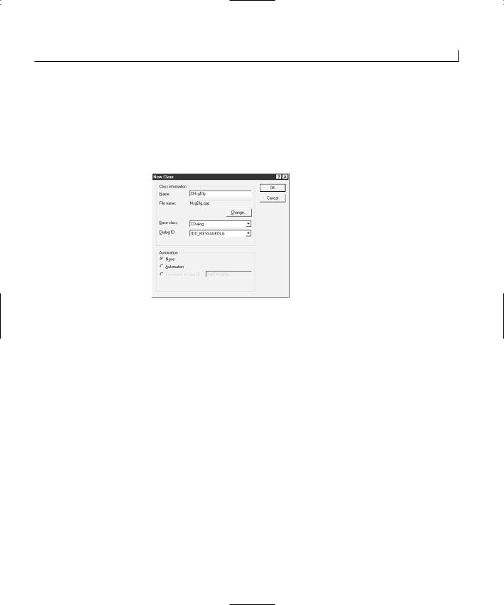
Getting User Feedback—Adding Dialog Boxes to Your Application |
95 |
8.Leave the selection on this dialog at the default setting of Create a New Class and click OK. Another dialog appears to allow you to specify the name for the new class and the base class from which it is inherited.
9.Enter the class name CMsgDlg into the Name field, and make sure that the Base Class is set to CDialog, as shown in Figure 5.8.
FIGURE 5.8.
The New Class dialog.
10.Click OK, leaving the other settings on this dialog at their defaults.
11.Once the Class Wizard opens, attach the variables to the controls on the new dialog as specified in Table 5.8.
TABLE 5.8. CONTROL VARIABLES. |
|
|
|
|
||
|
Object |
Name |
Category |
Type |
|
5 |
|
IDC_MESSAGE |
m_sMessage |
Value |
CString |
|
|
|
IDC_OPTION1 |
m_iOption |
Value |
int |
|
|
|
|
|
|
|
|
|
|
|
|
|
|
|
|
You should notice two things in the way that you configured the control properties and variables in the custom dialog. First, you should have selected the Group property on only the first of the radio buttons. This designates that all the radio buttons following that one belong to a single group, where only one of the radio buttons may be selected at a time. If you select the Group property on all the radio buttons, they are all independent of each other, allowing you to select all the buttons simultaneously. This property makes them behave somewhat like check boxes, but the primary difference is that the user would find it difficult to uncheck one of these controls due to the default behavior where one radio button in each group is always checked. The other difference is in their appearance; the radio buttons have round selection areas instead of the square areas of check boxes.
96 |
Day 5 |
The other thing to notice is that you declared a single integer variable for the one radio button with the Group property checked. This variable value is controlled by which radio button is selected. The first radio button causes this variable to have a value of 0, the second sets this variable to 1, and so on. Likewise, if you want to automatically select a particular radio button, you can set this variable to one less than the sequence number of the radio button in the group of radio buttons.
Note
Because this is the C++ programming language, all numbering begins with 0, not 1. Therefore, the first position in an array or a set of controls is position 0. The second position is position 1. The third position is number 2, and so on.
You have now finished all that you need to do to the second dialog window to make it ready for use. You would expect to need an UpdateData or two in the code behind the dialog, but because you didn’t remove the OK and Cancel buttons from the dialog, the UpdateData call is already performed when the user clicks the OK button. As a result, you don’t have to touch any code in this second dialog, only in the first dialog.
Using the Dialog in Your Application
Now that your custom dialog is ready for your application, using it is similar to the way that you use the common dialogs that are built into Windows. First, you have to declare an instance of the custom dialog class, which calls the class constructor and creates an instance of the class. Next, you call the dialog’s DoModal method and capture the return value of that function. Finally, you read the values of the variables that you associated with the controls on the dialog.
Creating the Dialog Instance
Before you can use your custom dialog in your application, you have to make your main dialog window aware of the custom dialog, its variables, and methods and how your main dialog can interact with your custom dialog. You accomplish this by including the header file for your custom dialog in the main source file for your main application dialog. Follow these steps:
1.Select the File View tab on the workspace pane.
2.Expand the Dialog Files and Source Files folders.
3.Double-click the DialogsDlg.cpp file. This opens the source code file for the main application dialog in the editing area of Developer Studio.
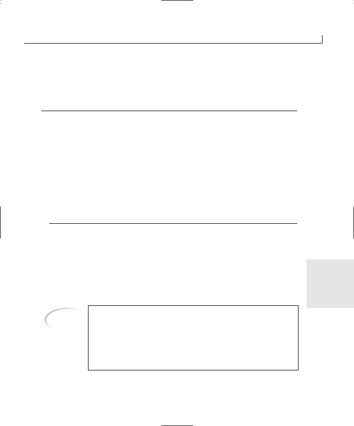
Getting User Feedback—Adding Dialog Boxes to Your Application |
97 |
4.Scroll to the top of the source code file where the #include statements are located, and add an include for the MsgDlg.h file before the DialogsDlg.h file, as in Listing 5.3.
LISTING 5.3. THE HEADER FILE INCLUDES.
1:// DialogsDlg.cpp : implementation file
2://
3:
4:#include “stdafx.h”
5:#include “Dialogs.h”
6:#include “MsgDlg.h”
7:#include “DialogsDlg.h”
9:#ifdef _DEBUG
10:#define new DEBUG_NEW
11:#undef THIS_FILE
12:static char THIS_FILE[] = __FILE__;
13:#endif
14:
15://///////////////////////////////////////////////////////////////////// 16: // CAboutDlg dialog used for App About
It is important that you place the #include statement for the MsgDlg.h file before the #include statement for the DialogsDlg.h file. The reason is that you will be adding a variable declaration for your custom dialog to the main dialog class in the main dialog’s header file. If the MsgDlg.h header file is included after the header file for the main dia-
log, the compiler will complain loudly and will refuse to compile your application until 5 you move the #include of the MsgDlg.h file above the #include of the DialogsDlg.h file.
The #include statement is what is known as a compiler directive in the C and
Note |
C++ programming languages. What it tells the compiler to do is read the |
|
contents of the file named into the source code that is being compiled. It is |
||
|
||
|
used to separate class, structure, and function declarations into a file that |
|
|
can be included in any source code that needs to be aware of the informa- |
|
|
tion in the header file. For more information on how the #include statements |
|
|
work, and why you use them, see Appendix A, “C++ Review.” |
Now that you have made your main application dialog aware of the custom dialog that

98 |
Day 5 |
you created, you need to declare a variable of your custom dialog. Follow these steps:
1.Select the Class View tab in the workspace pane.
2.Right-click the CDialogsDlg class to bring up the pop-up menu.
3.Select Add Member Variable from the pop-up menu.
4.Specify the Variable Type as CMsgDlg, the Variable Name as m_dMsgDlg, and the Access as Private. Click OK to add the variable to your main dialog.
If you expand the CDialogsDlg class in the tree view, you should see the instance of your custom dialog as a member of the main application dialog class. This means that you are ready to begin using the custom dialog in your application.
Calling the Dialog and Reading the Variables
Now that you have added your custom dialog to the main application dialog as a variable that is always available, not just as a local variable available only within a single function (as with the CFileDialog variable), you can add code to use the dialog. To do this, follow these steps:
1. Open the Class Wizard and add a function to the clicked event message of the button.
2. Add a function for the clicked event message (BN_CLICKED) for the IDC_ BWHICHOPTION button.
3. Edit the OnBcustomdialog function, adding the code in Listing 5.4.
LISTING 5.4. THE OnBcustomdialog FUNCTION.
1:void CDialogsDlg::OnBcustomdialog()
2:{
3:// TODO: Add your control notification handler code here
5:///////////////////////
6:// MY CODE STARTS HERE
7:///////////////////////
9:// Show the message dialog and capture the result
10:if (m_dMsgDlg.DoModal () == IDOK)
11:{
12:// The user checked OK, display the message the
13:// user typed in on the message dialog
14:m_sResults = m_dMsgDlg.m_sMessage;
15:// Update the dialog
16:UpdateData(FALSE);
17:// Enable the Which Option button
18:m_cWhichOption.EnableWindow(TRUE);
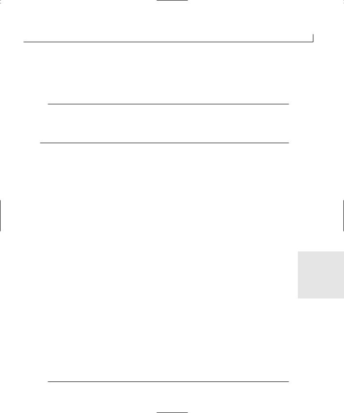
Getting User Feedback—Adding Dialog Boxes to Your Application
19: } 20:
21:///////////////////////
22:// MY CODE ENDS HERE
23:///////////////////////
24:}
4. Edit the OnBwhichoption function, adding the code in Listing 5.5.
LISTING 5.5. THE OnBwhichoption FUNCTION.
1:void CDialogsDlg::OnBwhichoption()
2:{
3:// TODO: Add your control notification handler code here
5:///////////////////////
6:// MY CODE STARTS HERE
7:///////////////////////
9:// Determine which radio button was selected, and display
10:// a message for the user to show which one was selected.
11:switch(m_dMsgDlg.m_iOption)
12:{
13:case 0: // Was it the first radio button?
14:m_sResults = “The first option was selected.”;
15:break;
16:case 1: // Was it the second radio button?
17:m_sResults = “The second option was selected.”;
18:break;
19:case 2: // Was it the third radio button?
20:m_sResults = “The third option was selected.”;
21:break;
22:case 3: // Was it the fourth radio button?
23:m_sResults = “The fourth option was selected.”;
24:break;
25:default: // Were none of the radio buttons selected?
26:m_sResults = “No option was selected.”;
27:break;
28:}
29:
30:// Update the dialog
31:UpdateData(FALSE);
33:///////////////////////
34:// MY CODE ENDS HERE
35:///////////////////////
99
5
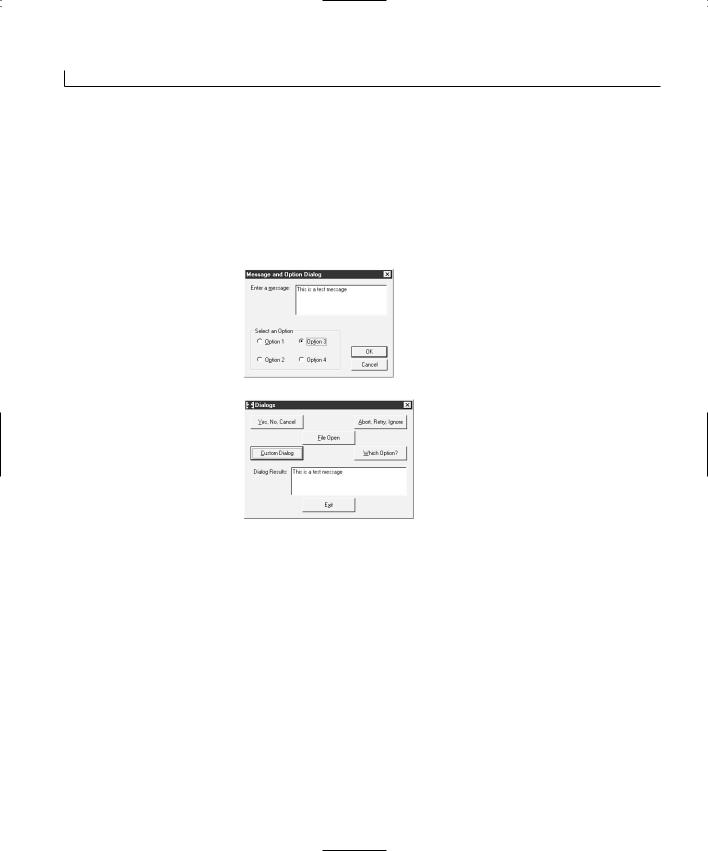
100 |
Day 5 |
In the first listing, you called the DoModal method of the custom dialog, which displayed the dialog for the user, waiting for the user to click one of the two buttons on the dialog, as in Figure 5.9. If the user clicks the OK button, you copy the message the user typed in the custom dialog into the edit box variable to be displayed to the user. After updating the dialog display with the new variable values, you enable the Which Option button, as shown in Figure 5.10. If the user clicks the Cancel button, none of this is done. The dialog display is not changed.
FIGURE 5.9.
The custom dialog allows the user to enter a message.
FIGURE 5.10.
The message entered on the custom dialog is displayed for the user.
When the user clicks the Which Option button, you pass the radio button variable on the custom dialog to a switch statement, selecting a message that tells the user which radio button was selected, as shown in Figure 5.11. Notice that in both of these functions, you can access the control variables on the custom dialog directly from the main dialog. That is because the Class Wizard automatically declares the variables associated with controls as public, making them completely accessible outside the dialog class. You can change this by placing a private: access specifier where the public: access specifier is. You don’t want to place anything after the //{{AFX_DATA line, where the variables are declared, because the variables are declared within an MFC Class Wizard macro, which enables the Developer Studio wizards to locate and manipulate the variables as needed without interfering with the Visual C++ compiler when you compile your application.
Getting User Feedback—Adding Dialog Boxes to Your Application |
101 |
FIGURE 5.11.
The option selected on the custom dialog is displayed for the user.
Summary
Today you learned how you can use additional dialog windows in your application to provide interactive experience for your users. You learned about the options available to you with the simple MessageBox function, how you can provide your users a variety of button combinations, and how you can determine which button the user selects. You saw how you can use this information to determine which path to take in your application logic.
You also learned about some of the common dialogs that are built into the Windows operating systems and how they have been encapsulated into C++ classes in the MFC class library. You learned how you can use the File Open dialog to present the user with the standard file selection dialog and how you can determine which file the user selected.
Finally, you learned how you can design your own additional dialogs that you can add to your applications to get information from the user and how you can capture that informa-
tion and use it in your application.
5
Q&A
QThere was no code added to the custom dialog. Do I have to design my custom dialogs this way, or can I add code to them?
AThe custom dialog windows are no different from the main dialog windows that you have been using in all your applications so far. If you need to control the behavior of the dialog on an interactive basis, you can put as much code into the dialog as you need. You didn’t add any code to the custom dialog today because there wasn’t any need to add any code. The only functionality that the dialog needed to perform was calling the UpdateData function before closing, which is automatically done by the OnOK function. Because you did not delete the OK and Cancel buttons, you already had this functionality built in.

102 |
Day 5 |
QWhat happens if I specify two or more button combinations in the same MessageBox function call?
ANothing happens. Your application compiles just fine, but when the MessageBox function is called, nothing happens. The message box does not open, and the user does not get to answer the question you are presenting.
QHow can I integrate the File Open dialog into my application where it opens in a specific directory that I specify?
AThe CFileDialog class has a public property called m_ofn. This property is a structure that contains numerous attributes of the File Open dialog, including the initial directory. This structure is defined as the OPENFILENAME structure in Listing 5.6.
LISTING 5.6. THE OPENFILENAME STRUCTURE.
1: typedef struct tagOFN { // ofn
2: |
DWORD |
lStructSize; |
3: |
HWND |
hwndOwner; |
4: |
HINSTANCE |
hInstance; |
5: |
LPCTSTR |
lpstrFilter; |
6: |
LPTSTR |
lpstrCustomFilter; |
7: |
DWORD |
nMaxCustFilter; |
8: |
DWORD |
nFilterIndex; |
9: |
LPTSTR |
lpstrFile; |
10: |
DWORD |
nMaxFile; |
11: |
LPTSTR |
lpstrFileTitle; |
12: |
DWORD |
nMaxFileTitle; |
13: |
LPCTSTR |
lpstrInitialDir; |
14: |
LPCTSTR |
lpstrTitle; |
15: |
DWORD |
Flags; |
16: |
WORD |
nFileOffset; |
17: |
WORD |
nFileExtension; |
18: |
LPCTSTR |
lpstrDefExt; |
19: |
DWORD |
lCustData; |
20:LPOFNHOOKPROC lpfnHook;
21: |
LPCTSTR |
lpTemplateName; |
22: } OPENFILENAME; |
|
|
You can set any of these attributes before calling the DoModal class method to control the behavior of the File Open dialog. For instance, if you set the starting directory to C:\Temp before calling the DoModal method, as in Listing 5.7, the File Open dialog opens in that directory.
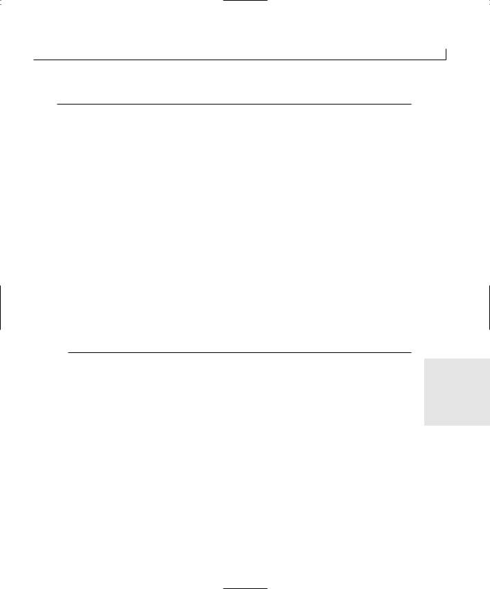
Getting User Feedback—Adding Dialog Boxes to Your Application |
103 |
LISTING 5.7. THE REVISED OnFileopen FUNCTION.
1:void CDialogsDlg::OnFileopen()
2:{
3:// TODO: Add your control notification handler code here
5:///////////////////////
6:// MY CODE STARTS HERE
7:///////////////////////
9: CFileDialog m_ldFile(TRUE); 10:
11:// Initialize the starting directory
12:m_ldFile.m_ofn.lpstrInitialDir = “C:\\Temp\\”;
14:// Show the File open dialog and capture the result
15:if (m_ldFile.DoModal() == IDOK)
16:{
17:// Get the filename selected
18:m_sResults = m_ldFile.GetFileName();
19:// Update the dialog
20:UpdateData(FALSE);
21:}
22:
23:///////////////////////
24:// MY CODE ENDS HERE
25:///////////////////////
26:}
5
Workshop
The Workshop provides quiz questions to help you solidify your understanding of the material covered and exercises to provide you with experience in using what you’ve learned. The answers to the quiz questions and exercises are provided in Appendix B, “Answers.”
Quiz
1.What are the possible return codes that your application might receive from the MessageBox function call when you specify the MB_RETRYCANCEL button combination?
2.What are the common dialogs that are built into the Windows operating systems that are defined as MFC classes?

104 |
Day 5 |
3.What is the difference between a modal dialog and a modeless dialog?
4.How can you display a File Save dialog for the user instead of the File Open dialog that you did have in your application?
5.Why did you not need to create any functions and add any code to your custom dialog?
Exercises
1.Modify your application so that it includes the directory with the filename in the application. (Hint: The GetFileName function returns the path and filename that was selected in the File Open dialog.)
2.Add a button on the custom dialog that calls the MessageBox function with a Yes or No selection. Pass the result back to the main application dialog.

WEEK 1
DAY 6
Creating Menus for Your Application
Most Windows applications use pull-down menus to provide the user a number of functions without having to provide buttons on the window. This enables you to provide your users a large amount of functionality while preserving most of your valuable screen real estate for other stuff.
Today you will learn
●How to create menus for your Visual C++ application
●How to attach a menu to your application’s main dialog window
●How to call application functions from a menu
●How to create a pop-up menu that can be triggered with the right mouse button
●How to set up accelerator keys for keyboard shortcuts to menus

106 |
Day 6 |
Menus
Back when the first computer terminals were introduced and users began using computer software, even on large mainframe systems software developers found the need to provide the users with some sort of menu of the functions that the computer could perform. These early menus were crude by today’s standards and were difficult to use and navigate. Menus have progressed since then; they’ve become standardized in how they are used and easy to learn.
The software designers that first came up with the idea of a graphical user interface (GUI) planned to make computer systems and applications easier to learn by making everything behave in a consistent manner. Menus used for selecting application functionality were one part of the GUI design that could be more easily learned if they all worked the same. As a result, a number of standard menu styles were developed.
Menu Styles
The first menu styles that were standardized are the pull-down and cascading menus. These are the menus with the categories all listed in a row across the top of the application window. If you select one of the categories, a menu drops down below the category, with a number of menu entries that can be selected to trigger various functions in the application.
A variation on this menu style is the cascading menu, which has another submenu that opens to the right of a menu entry. This submenu is similar to the pull-down menu, with a number of entries that trigger application functions. The menu designers placed no limit on how many cascading menus can be strung together, but it quickly became clear to most developers that more than two cascading levels is a little unwieldy.
Eventually, a third style of menu was developed, called a pop-up or context menu—a menu that pops up in the middle of the application area, floating freely above the application work area. This is also called a context menu because the specific menu that pops up is dependent on the selected object or workspace area where the cursor or mouse pointer is.
Keyboard Shortcut–Enabling Menus
When users began working with keyboard-intensive applications, such as word processors, it was discovered that taking your hands off the keyboard to use the mouse to make menu selections dramatically reduced productivity. Software designers decided that they needed to add keyboard shortcuts for the various menu entries (especially the most frequently used menu options). For this reason, keyboard shortcuts (accelerators) and hotkeys were added.

Creating Menus for Your Applications |
107 |
Hotkeys are letters that are underlined in each menu entry. If you press the Alt key with the underlined letter, you can select the menu entry that contains the underlined letter. This is a means of navigating application menus without taking your hands off the keyboard.
For more advanced users, application designers added keyboard shortcuts, or accelerators. An accelerator is a single key combination that you can press to trigger an application function instead of having to navigate through the application menus. This allows advanced users to avoid the overhead of using menus for the most common application functions. To enable users to learn what accelerators are available in an application, the key combination is placed on the menu entry that it can be used to replace, positioned at the right edge of the menu window.
Menu Standards and Conventions
Although there are no standards in how menus are designed, there are a number of conventions for how they are designed and organized. All these conventions are available in
Windows Interface Guidelines for Software Design, published by Microsoft for use by Windows software developers. The purpose of this publication is to facilitate the development of consistent application behaviors, which will help accomplish one of the primary goals behind the development of GUI systems. The conventions are as follows:
●Use single-word menu categories across the top menu bar. A two-word category can easily be mistaken for two one-word categories.
●The File menu is located as the first menu on the left. It contains all file-oriented functions (such as New, Open, Save, Print, and so on), as well as the Exit function. The Exit option is located at the bottom of the menu, separated from the rest of the menu entries by a border.
●The Edit menu is next to the File menu. The Edit menu contains all editing functions such as Copy, Cut, Paste, Undo, Redo, and so on.
● The View menu contains menu entries that control and affect the appearance of the |
6 |
|
application work area. |
||
|
●The Window menu is used in Multiple Document Interface (MDI) style applications. This has functions for controlling the child windows, selecting the current window, and altering the layout. This menu is the next-to-last menu from the right end of the menu bar.
●The Help menu is the final menu on the right end of the menu bar. It contains menu entries that provide instruction or documentation on the application. If the application has any copyrighted or corporate information that needs to be available for viewing, this should be located as the final entry on this menu, labeled About
<application name>.
108 |
Day 6 |
Designing Menus
Menus are defined as a resource in Visual C++ applications. Because they are a resource, you can design menus in the Visual C++ editor through the Resource View tab on the workspace pane. When you first create a dialog-style application, there won’t be a menu folder in the resource tree, but you can change that.
Note
Various aspects of Windows applications are considered to be resources, including window layouts, menus, toolbars, images, text strings, accelerators, and so on. All these features are organized in what is known as a resource file, which is used by the Visual C++ compiler to create these objects from their definitions. The resource file is a text file with an .rc filename extension and contains a textual description of all the various objects, including IDs, captions, dimensions, and so on.
Some resources, such as images and sounds, cannot be described in text, but have to be stored in a binary format. These resources are stored in individual files, with the filenames and locations included in the resource file.
Creating a Menu
Creating a menu is not difficult. You will follow several steps:
1.Create the application that will house the menu.
2.Add a menu resource to your project.
3.Customize the menu resource to include the menu items for your application.
4.Add functionality to your menu by connecting routines to your menu items.
Creating the Application
For the example in this chapter, you will create a simple dialog-style application that contains a single button and a menu. To create your application, do the following:
1.Create a new MFC AppWizard application, naming the project Menus.
2.Select the default AppWizard settings on all screens. For the dialog title, enter
Menus.
3.When the AppWizard has generated your application shell, delete all the controls from the dialog.
4.Add a single button to the dialog. Name the button IDC_EXIT, and specify the caption as E&xit.
Creating Menus for Your Applications |
109 |
5.Add a function to the button using the Class Wizard. Change the code in this function to call OnOK. Remember, the OnOK function causes the application to close.
Note
If you don’t remember how to add the OnOK function, review the section “Closing the Application” on Day 2, “Using Controls in Your Application,” for an example.
Adding and Customizing a Menu
Now that you have the basic application built, it’s time to start creating a menu for the application. To create a menu, you will first add a menu resource to your project. When you add the resource, Visual C++ automatically invokes the Menu Designer, which allows you to customize the menu. The following steps show you how to add and customize a menu:
1.Select the Resource View tab in the workspace pane.
2.Select the project resources folder at the top of the tree; in your example, this is Menus.
3.Right-click the mouse to bring up a pop-up menu.
4.Select Insert from the pop-up menu.
5.In the Insert Resource dialog that opens, select Menu from the list of available resources, as in Figure 6.1. Click the New button.
FIGURE 6.1.
The Insert Resource dialog.
6
6.The Menu Designer opens in the editing area of Developer Studio. The first menu spot is highlighted, as shown in Figure 6.2.
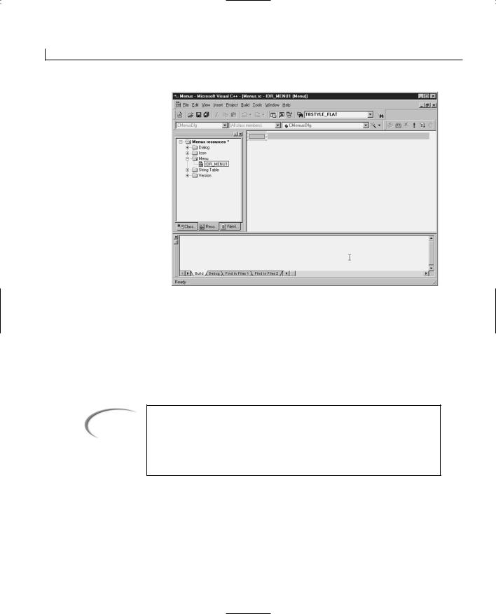
110 |
Day 6 |
FIGURE 6.2.
An empty menu.
At this point, you have created the menu resource and you are ready to customize it by adding menu items. To add a menu item, follow these steps:
1.Right-click the mouse on the highlighted area and select Properties from the popup menu.
2.Enter the menu item’s Caption. For this example, enter &File and close the Properties dialog.
Note
You are in the menu Properties dialog to specify the text that the user will see on the menu bar while the application is running. Because the Pop-up check box is checked (by default on any menu items on the top-level menu bar), this menu element doesn’t trigger any application functionality and thus doesn’t need to have an object ID assigned to it.
3.The first drop-down menu location is highlighted. To add this menu item, rightclick the mouse again on the highlighted area and select Properties from the popup menu.
4.Enter an ID and caption for the menu item. For this example, enter IDM_FILE_HELLO for the ID and &Hello for the Caption. Close the dialog.
Creating Menus for Your Applications |
111 |
Note
This time in the menu Properties dialog, you not only specify the text that the user will see when the menu is opened from the menu bar, but you also specify the object ID that will be used in the event message handler to determine what function receives each of the menu events.
At this point you have created a menu with a single menu item. You can continue to add menu items by repeating steps 3 and 4 of the preceding list for each of the highlighted areas. You can also add separators onto the menu. A separator is a dividing line that runs across the menu to separate two functional areas of menu selections. To add a separator, perform the following steps:
FIGURE 6.3.
Specifying a menu separator.
1.Select the highlighted area where you want the separator to be placed. In the example you created, the second drop-down menu location should be highlighted. Open the properties dialog as you did in step 3 in the preceding list. To add a separator, simply select the Separator option, as shown in Figure 6.3, and close the dialog.
To complete your sample program, follow the same steps I just described to add an Exit item to your File menu and a second menu called Help with one menu item called About. The following steps, which resemble the preceding list of steps, walk you through adding these additional items:
1.Open the properties dialog for the third drop-down location and specify the ID as IDM_FILE_EXIT and the caption as E&xit. Close the dialog.
2. Select the second top-level menu location and open the properties dialog. Specify |
6 |
the caption as &Help and close the dialog. |
|
3.Open the properties dialog for the first drop-down location on the second top-level menu. Specify the ID as ID_HELP_ABOUT and the caption as &About. Close the dialog.
At this point, your menu is created; however, it is not attached to your application.
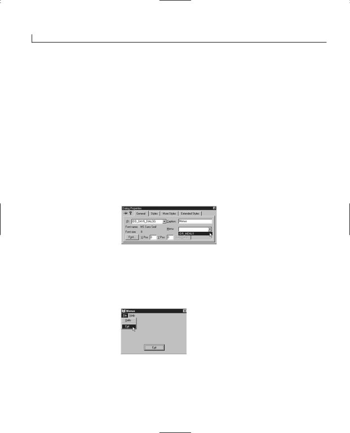
112 |
Day 6 |
Attaching the Menu to Your Dialog Window
You now have a menu that you can use in your application. If you compile and run your application at this point, however, the menu doesn’t appear. You still need to attach the menu to your dialog window. You can attach a menu by following these steps:
1.Open the dialog painter by double-clicking the primary application dialog in the Dialog folder in the Workspace pane. For this example, double-click on
IDD_MENUS_DIALOG.
2.Select the entire dialog window, making sure that no controls are selected, and open the dialog’s properties dialog. (What you are doing is opening the properties for the dialog window itself, not for any of the controls that might be on the window.)
3.Select the menu you have designed from the Menu drop-down list box, as shown in Figure 6.4.
FIGURE 6.4.
Attaching the menu to the dialog window.
If you compile and run your application, you find that the menu is attached to the application dialog, as shown in Figure 6.5. You can select menu entries as you do with any other Windows application—with one small difference. At this point, when you select one of the menu entries, nothing happens. You still need to attach functionality to your menu.
FIGURE 6.5.
The menu is now part of the application dialog.
Attaching Functionality to Menu Entries
Now that you have a menu as part of your application, it sure would be nice if it actually did something. Well, before your menu can do anything, you have to tell it what to do, just like everything else in your Visual C++ applications. To attach some functionality to your menu, follow these steps:
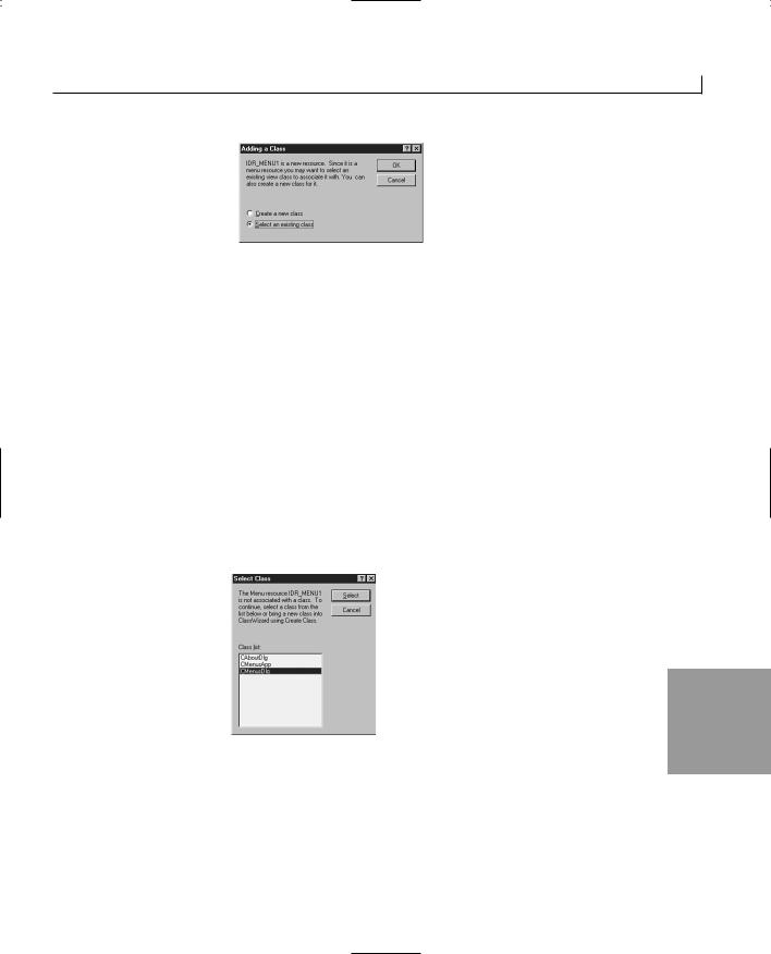
Creating Menus for Your Applications |
113 |
FIGURE 6.6.
The menu is now part of the application.
1.Open the Menu Designer to your menu.
2.Open the Class Wizard from the View menu.
3.The Adding a Class dialog is displayed for you, just as it was yesterday when you added a second dialog. Leave the dialog selection on Select an Existing Class and click OK (see Figure 6.6).
Yesterday, when you were adding a second dialog window to your application, you needed to create a new C++ class for that window. For today’s menu, you want to attach it to the existing C++ class for the dialog window to which the menu is attached.
4.Choose the C++ class of the primary dialog window from the list of available classes in the Select Class dialog. For this example, select CMenusDlg, as shown in Figure 6.7. This tells Visual C++ that all the functionality that you will call from the various menu entries is part of the same dialog class of the window that it’s attached to.
FIGURE 6.7.
The Select Class dialog.
6
For the menu elements that you want to use to trigger new functions in your application, you can add event-handler functions through the Class Wizard, just as you can with controls that you place on the dialog window.
For this example, add a function for the IDM_FILE_HELLO object (the Hello menu) on the C O M M A N D event message. Name the function OnHello and add the code in Listing 6.1 to the function.
114 |
Day 6 |
LISTING 6.1. THE ONHELLO FUNCTION.
1:void CMenusDlg::OnHello()
2:{
3:// TODO: Add your command handler code here
5:///////////////////////
6:// MY CODE STARTS HERE
7:///////////////////////
9:// Display a message for the user
10: MessageBox(“Hello there”, “Hello”); 11:
12:///////////////////////
13:// MY CODE ENDS HERE
14:///////////////////////
15:}
Note
The C O M M A N D event message is the message that is passed to the application window when a menu entry is selected. Placing a function on this event message has the same effect as placing a function on the menu entry selection.
You can call existing event handlers from menu elements by adding the existing function to the menu COMMAND event. You can do this by adding a function to the menu object ID and then specifying the existing function name instead of accepting the suggested function name.
To reuse the OnExit function for the Exit menu element, reopen the Menu Designer and then reopen the Class Wizard. When the Class Wizard is displayed, add a function for the IDM_FILE_EXIT object on the C OMMAN D event message. Do not accept the default function name presented to you by the Class Wizard. Enter the function name OnExit. This automatically attaches the existing OnExit function that you created with your Exit button earlier.
To round out your example’s functionality, add a function to the ID_HELP_ABOUT object on the COMMAND event message. Edit the function as in Listing 6.2.
LISTING 6.2. THE ONHELPA BOUT FUNCTION.
1:void CMenusDlg::OnHelpAbout()
2:{
3:// TODO: Add your command handler code here
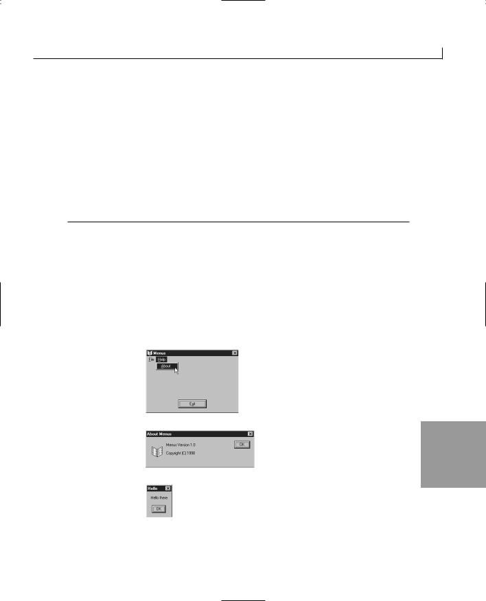
Creating Menus for Your Applications |
115 |
5:///////////////////////
6:// MY CODE STARTS HERE
7:///////////////////////
9:// Declare an instance of the About window
10: CAboutDlg dlgAbout; 11:
12:// Show the About window
13:dlgAbout.DoModal();
14:
15:///////////////////////
16:// MY CODE ENDS HERE
17:///////////////////////
18:}
You attached the File | Exit menu entry to an existing function that closes the application. On the File | Hello, you added a new function that called the MessageBox function to display a simple message to the user. With Help | About, you added another function that declared an instance of the About dialog window and called its DoModal method.
If you compile and run your application, you find that all the menu entries are working. If you select Help | About, as shown in Figure 6.8, you see the application About dialog (see Figure 6.9). If you select File | Hello, you see a Hello there message box, as shown in Figure 6.10. And if you select File | Exit, your application closes.
FIGURE 6.8.
The Help | About menu entry.
FIGURE 6.9. |
6 |
|
The About dialog. |
||
|
FIGURE 6.10.
The Hello there mes-
sage box.
116 |
Day 6 |
Creating Pop-Up Menus
Most Windows applications have what are called either pop-up or context menus, which are triggered by the user right-clicking an object. These are called pop-up menus because they pop up in the middle of the application area, not attached to a menu bar, the window frame, or anything else on the computer screen (not counting the mouse pointer). These menus are often referred to as context menus because the contents of a menu depend on the context in which it is opened; the elements available on the menu depend on what objects are currently selected in the application or what the mouse pointer is positioned over.
To provide a pop-up menu in your application, you have two approaches available. You can either design a menu specifically for use as a pop-up menu, or you can use one of the pull-down menus from the primary menu that you have already designed. If you design a menu specifically for use as a pop-up menu, you will need to skip the top-level, menu bar element by placing a space or some other text in the caption, knowing that it will not be seen. You will see how this works when you build a custom menu specifically for use as a pop-up menu on Day 11, “Creating Multiple Document Interface Applications,” in the section “Adding a Context Menu.”
Every drop-down portion of a menu can also be used as a pop-up menu. To use it in this way, you must get a handle to the submenu (the drop-down menu) and then call the TrackPopupMenu function on the submenu. The rest of the pop-up menu functionality is already covered in the other menu building and coding that you have already done. To add a pop-up menu to your application, follow these steps:
1.Using the Class Wizard, add a function for the WM_CONTEXTMENU event message in your dialog window.
Note
There are two dialog event messages that you can use to trigger your context menu. The event that you’d expect to use is the WM_RB UTTONDOWN event, which is triggered by the user right-clicking. The other event that can (and should) be used is the WM_CONTEXTMENU event, which is intended for use specifically to trigger a context menu. This event is triggered by a couple user actions: One of these is the release of the right mouse button, and another is the pressing of the context menu button on one of the newer Windows-enabled keyboards.
2. Edit the function, adding the code in Listing 6.3.

Creating Menus for Your Applications |
117 |
LISTING 6.3. THE ONCONTEXTM ENU FUNCTION.
1:void CMenusDlg:: OnContextMenu(CWnd* pWnd, CPoint point)
2:{
3:// TODO: Add your message handler code here
4:
5:///////////////////////
6:// MY CODE STARTS HERE
7:///////////////////////
9:// Declare local variables
10: |
CMenu *m_lMenu; |
// A pointer to the menu |
11: |
CPoint m_pPoint; |
// A copy of the mouse position |
12: |
|
|
13:// Copy the mouse position to a local variable
14:m_pPoint = point;
15:// Convert the position to a screen position
16:ClientToScreen(&m_pPoint);
17:// Get a pointer to the window menu
18:m_lMenu - GetMenu();
19:// Get a pointer to the first submenu
20:m_lMenu = m_lMenu->GetSubMenu(0);
21:// Show the Popup Menu
22:m_lMenu->TrackPopupMenu(TPM_CENTERALIGN + TPM_LEFTBUTTON,
23:m_pPoint.x, m_pPoint.y, this, NULL);
24:
25:///////////////////////
26:// MY CODE ENDS HERE
27:///////////////////////
28:}
In Listing 6.3, the first thing that you did was make a copy of the mouse position. This |
|
mouse position is a relative position within the window area. It must be converted to an |
|
absolute position on the entire screen area for displaying the pop-up menu. If you don’t |
|
convert the position coordinates, you can’t predict where your pop-up menu will appear. |
|
After you convert the position to an absolute position, you get a pointer to the window |
6 |
menu. This pointer should always be a local pointer within the function where you are going to use it because the location of the menu might change as the application runs. From the menu pointer, you next get a pointer to the first drop-down menu (submenu numbering begins with 0, like just about everything else in C/C++). After you have a pointer to the submenu, you can treat it as a regular CMenu class instance.
The final piece in this puzzle is the call to the CMenu member function TrackPopupMenu.
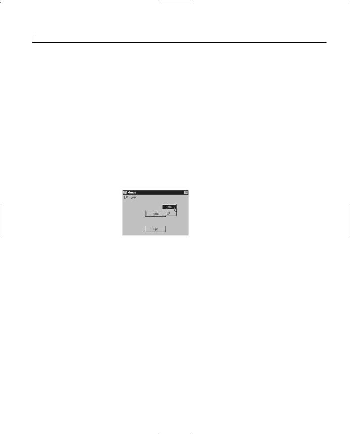
118 |
Day 6 |
This function takes five arguments and uses them to determine where and how to show the pop-up menu. The first argument is a combination of two flags. The first flag, TPM_CENTERALIGN, centers the pop-up menu on the mouse point. You can also use TPM_LEFTALIGN or TPM_RIGHTALIGN instead. These flags line up the left or right edge of the pop-up menu with the mouse position. The second part of this flag combination is TPM_LEFTBUTTON, which makes the pop-up menu trigger from the left mouse button. You can also use to make the menu trigger from the right mouse button.
The second and third arguments to the TrackPopupMenu function specify the screen position for the pop-up menu. This is the absolute position on the screen, not a relative position within the window area. The fourth argument is a pointer to the window that receives the menu command messages. The final argument is a rectangle that the user can click without closing the pop-up menu. By passing NULL, you specify that if the user
FIGURE 6.11.
The pop-up menu in action.
clicks outside the pop-up menu, the menu closes. This code enables you to include a pop-up menu in your application, as shown in Figure 6.11.
Creating a Menu with Accelerators
One of the original keyboard shortcuts for selecting menu entries were accelerator keys. As mentioned earlier in the chapter, accelerator keys are specific key combinations, usually the Ctrl key combined with another key, or function keys, that are unique within the entire application. Each of these key combinations triggers one menu event function.
The way that accelerator keys work is similar to the way menus work. They are also an application resource that is defined in a table in the resource tab of the workspace pane. Each table entry has an object ID and a key code combination. After you define the accelerators, you can attach functionality to the object IDs. You can also assign accelerator entries the same object ID as the corresponding menu entry so that you have to define only a single entry in the application message map.
After you define all your accelerator keys, you can add the key combination to the menu

Creating Menus for Your Applications |
119 |
entry so that the user will know about the accelerator key combination. Add \t to the end of the menu entry caption, followed by the key combination. The \t is replaced in the menu display by a tab, which separates the menu caption from the accelerator key combination.
Unfortunately, accelerator keys don’t work in dialog-style windows, so you cannot add them to today’s application. You will learn how to attach accelerator keys to menus in a few days when you learn about single and multi-document interface style applications.
Summary
Today you learned about menus in Visual C++ applications. You learned how to use the tools in Visual C++ to create a menu for use in your application and then how to attach the menu to a window in your application. After you had the menu attached to your window, you learned how to attach functionality to the various menu entries. Later in the day, you learned how you can use a portion of your menu as a pop-up, or context, menu. Finally, you learned how accelerator keys are added to most applications.
Q&A
QDo I have to name my menu items the same names everyone else uses?
For example, a lot of applications use File and Help. Can I name my menus something else?
AYou can name your top-level menus anything you want. However, there are accepted menu name conventions that place all file-oriented functionality under a menu labeled File and all help-related functionality under a menu labeled Help. If you have a menu with entries such as Broccoli, Corn, and Carrots, you will probably want to call the menu Vegetables, although an equally valid label would be Food or Plants. In general, if you want to make your application easy for your
users to learn, you will want to use menu labels that make sense for the entries o |
6 |
|
n the pull-down portion of the menu. |
||
|
Q Why can’t I specify a single character as an accelerator key?
AThe single character would trigger the WM_KEY messages, not the menu messages. When the designers of Windows were deciding how accelerator keys would work, they decided that single-character keys would most likely be input to the active

120 |
Day 6 |
application. If they had allowed single-character accelerators, Windows wouldn’t be able to determine whether the character was input or a shortcut. By requiring a key combination (with the exception of function keys), the designers ensured that Windows won’t have to make this determination.
Workshop
The Workshop provides quiz questions to help you solidify your understanding of the material covered and exercises to provide you with experience in using what you’ve learned. The answers to the quiz questions are provided in Appendix B, “Answers.”
Quiz
1.What event message does a menu selection send to the window message queue?
2.How do you attach a menu to a dialog window?
3.Which existing class do you specify for handling event messages for the menu?
4.What event message should a pop-up menu be triggered by?
Exercises
1.Add a button to the main window and have it call the same function as the Hello menu entry.
2.Add a pop-up menu to your application that uses the Help drop-down menu as the pop-up menu.
WEEK 1
DAY 7
Working with Text and Fonts
In most Windows applications, you don’t need to worry about specifying fonts, much less their weight, height, and so on. If you don’t specify the font to be used, Windows supplies a default font for your application. If you do need to use a particular font, you can specify a font to use for a particular dialog window through the dialog properties. Sometimes, however, you want or need to control the font used in your application. You might need to change the font being used or allow the user to select a font to use in a particular instance. It is for those circumstances that you will learn how to change and list fonts today. Among the things that you will learn are
•How to build a list of available fonts.
•How to specify a font for use.
•How to change fonts dynamically.

122 |
Day 7 |
Finding and Using Fonts
One of the first things that you need to know when working with fonts is that not every system that your applications run on will have the same fonts installed. Fonts are specified in files that can be installed and removed from Windows systems with relative ease. Every computer user can customize his system with whatever combination of fonts he wants. If you specify a font that doesn’t exist on the system, Windows will choose either the system default font or what the operating system considers to be a reasonably close alternative font.
What you can do instead is ask the operating system what fonts are available. This method allows you to make your own decisions on which font to use or let the user make the decision. When you ask what fonts are available, you can limit the types of fonts that are listed, or you can choose to list them all and select various fonts based on various attributes.
Listing the Available Fonts
To get a list of all available fonts on a computer, you call a Windows API (Application Programming Interface) function called EnumFontFamiliesEx. This function tells Windows that you want a list of the fonts on the system. Before you start using this function and expecting it to pass you a big list of available fonts, you need to understand how it gives you the list.
Callback Functions
One of the key arguments to the EnumFontFamiliesEx function is the address of another function. This second function is what is known as a callback function, which is called by the operating system. For almost every enumeration function in the Windows operating system, you pass the address of a callback function as an argument because the callback function is called once for each of the elements in the enumerated list. In other words, you have to include a function in your application to receive each individual font that is on the system and then build the list of fonts yourself.
When you create this function to receive each font and build your list, you cannot define your callback function in any way you want. All callback functions are already defined in the Windows API. You have to use a specific type of callback function to receive the list of fonts. For getting a list of fonts, the function type is EnumFontFamProc. This function type specifies how your function must be defined, what its arguments must be, and what type of return value it must return. It does not specify what your function should be named or how it needs to work internally. These aspects are left completely up to you.

Working with Text and Fonts |
123 |
The EnumFontFamiliesEx Function
The EnumFontFamiliesEx function, which you call to request the list of available fonts, takes five arguments. A typical use of this function follows:
// Create a device context variable CClientDC dc (this);
// Declare a LOGFONT structure LOGFONT lLogFont;
// Specify the character set lLogFont.lfCharSet = DEFAULT_CHARSET; // Specify all fonts lLogFont.lfFaceName[0] = NULL;
// Must be zero unless Hebrew or Arabic lLogFont.lfPitchAndFamily = 0;
// Enumerate the font families ::EnumFontFamiliesEx((HDC) dc, &lLogFont, (FONTENUMPROC) EnumFontFamProc, (LPARAM) this, 0);
The first argument is a device context, which can be an instance of the CClientDC class. Every application running within the Windows operating system has a device context. The device context provides a lot of necessary information to the operating system about what is available to the application and what is not.
The second argument is a pointer to a LOGFONT structure. This structure contains information about the fonts that you want listed. You can specify in this structure which character set you want to list or whether you want all the fonts in a particular font family. If you want all the fonts on the system, you pass NULL in the place of this argument.
The third argument is the address of the callback function that will be used to build your list of fonts. Passing the address of your callback function is a simple matter of using the function name as the argument. The Visual C++ compiler takes care of replacing the function name with the function address. However, you do need to cast the function as the type of callback function that the function requires.
The fourth argument is a LPARAM value that will be passed to the callback function. This parameter is not used by Windows but provides your callback function with a context in which to build the font list. In the example, the value being passed is a pointer to the window in which the code is being run. This way, the callback function can use this pointer to access any structures it needs to build the list of fonts. This pointer can also be
the first node in a linked list of fonts or other such structure. |
7 |
|
The fifth and final argument is always 0. This reserved argument may be used in future versions of Windows, but for now, it must be 0 so that your application passes a value that won’t cause the function to misbehave.

124 |
Day 7 |
The EnumFontFamProc Function Type
When you create your callback function, it must be defined as an independent function, not as a member of any C++ class. A typical EnumFontFamProc function declaration follows:
int CALLBACK EnumFontFamProc( LPENUMLOGFONT lpelf, LPNEWTEXTMETRIC lpntm,
DWORD nFontType, long lParam)
{
//Create a pointer to the dialog window CMyDlg* pWnd = (CMyDlg*) lParam;
//Add the font name to the list box
pWnd->m_ctlFontList.AddString(lpelf->elfLogFont.lfFaceName); // Return 1 to continue font enumeration
return 1;
}
The first argument to this function is a pointer to an ENUMLOGFONTEX structure. This structure contains information about the logical attributes of the font, including the font name, style, and script. You may have numerous fonts listed with the same name but different styles. You can have one for normal, one for bold, one for italic, and one for bold italic.
The second argument is a pointer to a NEWTEXTMETRICEX structure. This structure contains information about the physical attributes of the font, such as height, width, and space around the font. These values are all relative in nature because they need to scale as the font is made larger or smaller.
The third argument is a flag that specifies the type of font. This value may contain a combination of the following values:
•DEVICE_FONTYPE
•RASTER_FONTYPE
•TRUETYPE_FONTYPE
Finally, the fourth argument is the value that was passed into the EnumFontFamiliesEx function. In the example, it was a pointer to the dialog on which the list of fonts is being built. If you cast this value as a pointer to the dialog, the function can access a list box control to add the font names.
The return value from this function determines whether the listing of fonts continues. If 0 is returned from this function, the operating system quits listing the available fonts. If 1
Working with Text and Fonts |
125 |
is returned, the operating system continues to list the available fonts.
Using a Font
To use a particular font in an application, you call an instance of the CFont class. By calling the CreateFont method, you can specify the font to be used, along with the size, style, and orientation. Once you’ve created a font, you can tell a control or window to use the font by calling the object’s SetFont method. An example of this process follows:
CFont m_fFont; |
// The font to be used |
// Create the font to be used m_fFont.CreateFont(12, 0, 0, 0, FW_NORMAL,
0, 0, 0, DEFAULT_CHARSET, OUT_CHARACTER_PRECIS, CLIP_CHARACTER_PRECIS, DEFAULT_QUALITY, DEFAULT_PITCH | FF_DONTCARE, m_sFontName);
Tip
The CFont variable used in the previous code should be declared as a member variable of the class in which this code is placed. In the sample code, it is declared above where it is used to show how it is declared. This variable should not be declared or used as a local variable in a function.
// Set the font for the display area m_ctlDisplayText.SetFont(&m_fFont);
Seems simple enough—just two function calls—but that CreateFont function needs an awful lot of arguments passed to it. It is these arguments that make the CreateFont method a flexible function with a large amount of functionality. Once you create the font, using it is a simple matter of passing the font to the SetFont method, which is a member of the CWnd class and thus available to all window and control classes in Visual C++. This means that you can use this technique on any visible object within a Visual C++ application.
To understand how the CreateFont function works, let’s look at the individual arguments that you have to pass to it. The function is defined as
BOOL CreateFont( |
|
int nHeight, |
|
int nWidth, |
7 |
int nEscapement, |
int nOrientation, int nWeight,

126 |
Day 7 |
BYTE bItalic,
BYTE bUnderline,
BYTE cStrikeOut,
BYTE nCharSet,
BYTE nOutPrecision,
BYTE nClipPrecision,
BYTE nQuality,
BYTE nPitchAndFamily,
LPCTSTR lpszFaceName);
The first of these arguments, nHeight, specifies the height of the font to be used. This logical value is translated into a physical value. If the value is 0, a reasonable default value is used. If the value is greater or less than 0, the absolute height is converted into device units. It is key to understand that height values of 10 and -10 are basically the same.
The second argument, nWidth, specifies the average width of the characters in the font. This logical value is translated into a physical value in much the same way as the height is.
The third argument, nEscapement, determines the angle at which the text will be printed. This value is specified in 0.1-degree units in a counterclockwise pattern. If you want to print vertical text that reads from bottom to top, you supply 900 as the value for this argument. For printing normal horizontal text that flows from left to right, supply 0 as this value.
The fourth argument, nOrientation, determines the angle of each individual character in the font. This works on the same basis as the previous argument, but it controls the output on a character basis, not a line-of-text basis. To print upside-down characters, set this value to 1800. To print characters on their backs, set this value to 900.
The fifth argument, nWeight, specifies the weight, or boldness, of the font. This can be any value from 0 to 1000, with 1000 being heavily bolded. You can use constants defined for this argument to control this value with ease and consistency. These constants are
listed in Table 7.1.
TABLE 7.1. FONT WEIGHT CONSTANTS.
Constant |
Value |
FW_DONTCARE |
0 |
FW_THIN |
100 |
FW_EXTRALIGHT |
200 |
FW_ULTRALIGHT |
200 |

Working with Text and Fonts |
127 |
FW_LIGHT |
300 |
FW_NORMAL |
400 |
FW_REGULAR |
400 |
FW_MEDIUM |
500 |
Constant |
Value |
|
|
FW_SEMIBOLD |
600 |
FW_DEMIBOLD |
600 |
FW_BOLD |
700 |
FW_EXTRABOLD |
800 |
FW_ULTRABOLD |
800 |
FW_BLACK |
900 |
FW_HEAVY |
900 |
|
|
The actual interpretation and availability of these weights depend on the font. Some fonts only have FW_NORMAL, FW_REGULAR, and FW_BOLD weights. If you specify FW_DONTCARE, a default weight is used, just as with most of the rest of the arguments.
The sixth argument, bItalic, specifies whether the font is to be italicized. This is a boolean value; 0 indicates that the font is not italicized, and any other value indicates that the font is italicized.
The seventh argument, bUnderline, specifies whether the font is to be underlined. This is also a boolean value; 0 indicates that the font is not underlined, and any other value indicates that the font is underlined.
The eighth argument, cStrikeOut, specifies whether the characters in the font are displayed with a line through the character. This is another boolean value using a non-zero value as TRUE and 0 as FALSE.
|
The ninth argument, nCharSet, |
specifies the font’s character set. The available constants |
|
||
|
for this value are listed in Table 7.2. |
|
|||
TABLE 7.2. FONT CHARACTER SET CONSTANTS. |
|
||||
|
|
|
|
|
|
|
Constant |
Value |
|
||
7 |
|||||
|
|
|
|
||
|
ANSI_CHARSET |
0 |
|
||
|
|
|
|||
|
DEFAULT_CHARSET |
1 |
|
|
|
|
SYMBOL_CHARSET |
2 |
|
|
|
|
SHIFTJIS_CHARSET |
128 |
|
|
|
|
|
|
|
|
|

128 |
Day 7 |
OEM_CHARSET |
255 |
The system on which your application is running might have other character sets, and the OEM character set is system dependent, making it different for systems from different manufacturers. If you are using one of these character sets, it is risky to try to manipulate the strings to be output, so it’s best to just pass along the string to be displayed.
The tenth argument, nOutPrecision, specifies how closely the output must match the requested font’s height, width, character orientation, escapement, and pitch. The available values for this argument are
•OUT_CHARACTER_PRECIS
•OUT_DEFAULT_PRECIS
•OUT_DEVICE_PRECIS
•OUT_RASTER_PRECIS
•OUT_STRING_PRECIS
•OUT_STROKE_PRECIS
•OUT_TT_PRECIS
The OUT_DEVICE_PRECIS, OUT_RASTER_PRECIS, and OUT_TT_PRECIS values control which font is chosen if there are multiple fonts with the same name. For instance, if you use the OUT_TT_PRECIS value and specify a font with both a TrueType and raster version, then the TrueType version is used. In fact, the OUT_TT_PRECIS value forces the system to use a TrueType font, even when the specified font does not have a TrueType version.
The eleventh argument, nClipPrecision, specifies how to clip characters that are partially outside of the display area. The values for this argument are
•CLIP_CHARACTER_PRECIS
•CLIP_DEFAULT_PRECIS
•CLIP_ENCAPSULATE
•CLIP_LH_ANGLES
•CLIP_MASK
•CLIP_STROKE_PRECIS
•CLIP_TT_ALWAYS
These values can be O Red together to specify a combination of clipping techniques.
The twelfth argument, nQuality, specifies the output quality and how carefully the GDI (Graphics Device Interface) must attempt to match the logical font attributes to the phys-

Working with Text and Fonts |
129 |
ical font output. The available values for this argument are
•DEFAULT_QUALITY
•DRAFT_QUALITY
•PROOF_QUALITY
The thirteenth argument, nPitchAndFamily, specifies the pitch and family of the font. This value consists of two values that are O Red together to create a combination value. The first set of available values is
•DEFAULT_PITCH
•VARIABLE_PITCH
•FIXED_PITCH
This value specifies the pitch to be used with the font. The second set of available values specifies the family of fonts to be used. The available values for this portion of the argument are
•FF_DECORATIVE
•FF_DONTCARE
•FF_MODERN
•FF_ROMAN
•FF_SCRIPT
•FF_SWISS
The font family describes in a general way the appearance of a font. You can use the font family value to choose an alternative font when a specific font does not exist on a system. The final argument, lpszFacename, is a standard C-style string that contains the name of the font to be used. This font name comes from the font information received by the EnumFontFamProc callback function.
Using Fonts
Today you will build an application that allows the user to select from a list of available fonts to be displayed. The user will be able to enter some text to be displayed in the
selected font, allowing the user to see what the font looks like.
7
Creating the Application Shell
To begin today’s application, follow these steps:
1. Create a new project workspace using the MFC AppWizard. Name the project
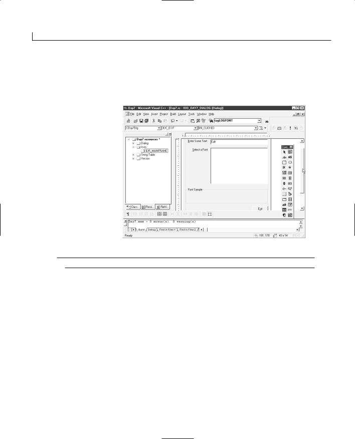
130 |
Day 7 |
FIGURE 7.1. Day7.
The main dialog
2. Use the same defaults that you used for the previous day’s projects, giving the
layout.
application a title of Fonts.
3. Design the main dialog as in Figure 7.1, using the properties in Table 7.3.
TABLE 7.3. CONTROL PROPERTY SETTINGS.
Object |
Property |
Setting |
Static Text
Edit Box
Static Text
List Box
Group Box
Static Text
(inside group box; size to fill the group box)
ID |
IDC_STATIC |
Caption |
&Enter Some Text: |
ID |
IDC_ESAMPTEXT |
ID |
IDC_STATIC |
Caption |
&Select a Font |
ID |
IDC_LFONTS |
ID |
IDC_STATIC |
Caption |
Font Sample |
ID |
IDC_DISPLAYTEXT |
Caption |
Empty string |
Command Button |
ID |
IDC_EXIT |
Working with Text and Fonts |
131 |
Caption |
E&xit |
4. Using the Class Wizard, add the variables in Table 7.4 to the controls on the dialog.
TABLE 7.4. CONTROL VARIABLES.
Object |
Name |
Category |
Type |
IDC_DISPLAYTEXT |
m_ctlDisplayText |
Control |
CStatic |
|
m_strDisplayText |
Value |
CString |
IDC_LFONTS |
m_ctlFontList |
Control |
CListBox |
|
m_strFontName |
Value |
CString |
IDC_ESAMPTEXT |
m_strSampText |
Value |
CString |
|
|
|
|
5.Attach a function to the IDC_EXIT button to close the application, as in the previous day’s applications.
Building a List of Fonts
To be able to create your list of fonts, you need to add your callback function to get each font list and add it to the list box that you placed on the dialog window. To do this, edit the Day7Dlg.h header file and add the function declaration in Listing 7.1 near the top of the file. This function cannot be added through any of the tools available in Visual C++. You need to open the file and add it yourself.
LISTING 7.1. THE CALLBACK FUNCTION DECLARATION IN THE Day7Dlg.h HEADER FILE.
1:#if _MSC_VER > 1000
2:#pragma once
3:#endif // _MSC_VER > 1000
5:int CALLBACK EnumFontFamProc(LPENUMLOGFONT lpelf,
6:LPNEWTEXTMETRIC lpntm, DWORD nFontType, long lParam);
8:////////////////////////////////////////////////////////////////////
9:// CDay7Dlg dialog
10:
11:class CDay7Dlg : public CDialog
12:.
13: . |
7 |
|
|
14: . |
|
132 |
Day 7 |
Once you add the function declaration to the header file, open the Day7Dlg.cpp sourcecode file, scroll to the bottom of the file, and add the function definition in Listing 7.2.
LISTING 7.2. THE CALLBACK FUNCTION DEFINITION IN THE Day7Dlg.cpp SOURCE FILE.
1:int CALLBACK EnumFontFamProc(LPENUMLOGFONT lpelf,
2:LPNEWTEXTMETRIC lpntm, DWORD nFontType, long lParam)
3:{
4:// Create a pointer to the dialog window
5:CDay7Dlg* pWnd = (CDay7Dlg*) lParam;
6:
7:// Add the font name to the list box
8:pWnd->m_ctlFontList.AddString(lpelf->elfLogFont.lfFaceName);
9:// Return 1 to continue font enumeration
10:return 1;
11:}
Now that you have the callback function defined, you need to add a function to request the list of fonts from the operating system. To add this function, follow these steps:
1.Select the Class View tab on the project workspace pane.
2.Select the CDay7Dlg class, right-click the mouse, and select Add Member Function from the pop-up menu.
3.Specify the function type as void, the function declaration as FillFontList, and the access as Private. Click the OK button to close the dialog and add the function.
4.Edit the function definition as in Listing 7.3.
LISTING 7.3. THE FillFontList FUNCTION.
1:void CDay7Dlg::FillFontList()
2:{
3:LOGFONT lf;
4:
5:// Initialize the LOGFONT structure
6:lf.lfCharSet = DEFAULT_CHARSET;
7:strcpy(lf.lfFaceName, “”);
8:// Clear the list box
9:m_ctlFontList.ResetContent();
10:// Create a device context variable
11:CClientDC dc (this);
12:// Enumerate the font families
13:::EnumFontFamiliesEx((HDC) dc, &lf,
14:(FONTENUMPROC) EnumFontFamProc, (LPARAM) this, 0);
15:}
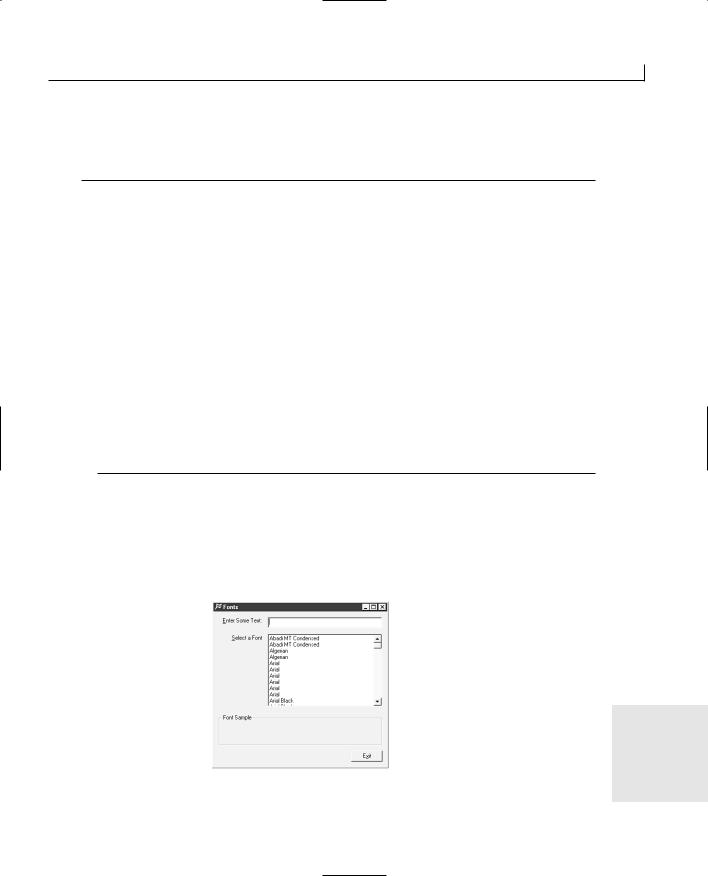
Working with Text and Fonts |
133 |
5. Edit the OnInitDialog function to call the FillFontList function, as in Listing 7.4.
LISTING 7.4. THE EDITED OnInitDialog FUNCTION.
1:BOOL CDay7Dlg::OnInitDialog()
2:{
3:CDialog::OnInitDialog();
7:// TODO: Add extra initialization here
9:///////////////////////
10:// MY CODE STARTS HERE
11:///////////////////////
13:// Fill the font list box
14:FillFontList();
15:
16:///////////////////////
17:// MY CODE ENDS HERE
18:///////////////////////
20:return TRUE; // return TRUE unless you set the focus to a control
21:}
If you compile and run your application now, you should find that your list box is filled with the names of all the fonts available on the system. However, there’s one aspect of this list that you probably don’t want in your application. Figure 7.2 shows many duplicate entries in the list of fonts in the list box. It would be nice if you could eliminate
FIGURE 7.2.
these duplicates and have only one line per font.
Listing all the fonts in the system.
7

134 |
Day 7 |
It turns out that the EnumFontFamiliesEx function call is synchronous in nature. This means that it doesn’t return until all the fonts in the system are listed in calls to your callback function. You can place code in the FillFontList function to remove all the duplicate entries once the list box is filled. To do this, modify the FillFontList function as in Listing 7.5.
LISTING 7.5. THE MODIFIED FillFontList FUNCTION.
1:void CDay7Dlg::FillFontList()
2:{
3: |
int iCount; |
// The number of fonts |
|
4: |
int iCurCount; |
// The current font |
|
5: |
CString strCurFont; |
|
// The current font name |
6: |
CString strPrevFont = “”; |
// The previous font name |
|
7: |
LOGFONT lf; |
|
|
8: |
|
|
|
9:// Initialize the LOGFONT structure
10:lf.lfCharSet = DEFAULT_CHARSET;
11:strcpy(lf.lfFaceName, “”);
12:// Clear the list box
13:m_ctlFontList.ResetContent();
14:// Create a device context variable
15:CClientDC dc (this);
16:// Enumerate the font families
17:::EnumFontFamiliesEx((HDC) dc, &lf,
18:(FONTENUMPROC) EnumFontFamProc, (LPARAM) this, 0);
19:// Get the number of fonts in the list box
20:iCount = m_ctlFontList.GetCount();
21:// Loop from the last entry in the list box to the first,
22:// searching for and deleting the duplicate entries
23:for (iCurCount = iCount; iCurCount > 0; iCurCount--)
24:{
25:// Get the current font name
26:m_ctlFontList.GetText((iCurCount - 1), strCurFont);
27:// Is it the same as the previous font name?
28:if (strCurFont == strPrevFont)
29:{
30:// If yes, then delete it
31:m_ctlFontList.DeleteString((iCurCount - 1));
32:}
33:// Set the previous font name to the current font name
34:strPrevFont = strCurFont;
35:}
36:}
Notice that the for loop started at the end of the list and worked backward. This allowed you to delete the current entry without worrying about manipulating the loop counter to

Working with Text and Fonts |
135 |
prevent skipping lines in the list box. If you compile and run your application, there shouldn’t be any duplicate entries in the list of available fonts.
Setting the Font Sample Text
Before you can display the font for the user, you need to place some text into the display area. The edit box near the top of the dialog is where the user enters text to be displayed in the font selected. To add the functionality, do the following:
1.Edit the OnInitDialog function to add code to initialize the edit box and display text, as in Listing 7.6.
LISTING 7.6. THE MODIFIED OnInitDialog FUNCTION.
1:BOOL CDay7Dlg::OnInitDialog()
2:{
3:CDialog::OnInitDialog();
7:// TODO: Add extra initialization here
9:///////////////////////
10:// MY CODE STARTS HERE
11:///////////////////////
13:// Fill the font list box
14:FillFontList();
15:
16:// Initialize the text to be entered
17:m_strSampText = “Testing”;
18:// Copy the text to the font sample area
19:m_strDisplayText = m_strSampText;
20:// Update the dialog
21:UpdateData(FALSE);
22:
23:///////////////////////
24:// MY CODE ENDS HERE
25:///////////////////////
27:return TRUE; // return TRUE unless you set the focus to a control
28:}
|
|
7 |
|
2. Using the Class Wizard, add a function on the EN_CHANGE event message for the |
|||
|
|||
IDC_ESAMPTEXT edit box control. |
|
||
|
|
|
|
136 |
Day 7 |
3. Edit the function you just added, adding the code in Listing 7.7.
LISTING 7.7. THE OnChangeEsamptext FUNCTION.
1:void CDay7Dlg::OnChangeEsamptext()
2:{
3:// TODO: If this is a RICHEDIT control, the control will not
4:// send this notification unless you override the
CDialog::OnInitialUpdate()
5:// function and call CRichEditCrtl().SetEventMask()
6:// with the EN_CHANGE flag ORed into the mask.
8: // TODO: Add your control notification handler code here 9:
10:///////////////////////
11:// MY CODE STARTS HERE
12:///////////////////////
14:// Update the variables with the dialog controls
15:UpdateData(TRUE);
16:
17:// Copy the current text to the font sample
18:m_strDisplayText = m_strSampText;
19:
20:// Update the dialog with the variables
21:UpdateData(FALSE);
22:
23:///////////////////////
24:// MY CODE ENDS HERE
25:///////////////////////
26:}
If you compile and run your application, you should be able to type text into the edit box and see it change in the font display area in the group box below.
Selecting a Font to Display
Before you can start changing the font for the display area, you’ll need to have a CFont member variable of the dialog class that you can use to set and change the display font. To add this variable, follow these steps:
1.In the Class View of the workspace pane, right-click the mouse on the CDay7Dlg class. Select Add Member Variable from the pop-up menu.
2.Specify the variable type as CFont, the variable name as m_fSampFont, and the access as Private. Click the OK button to close the dialog box and add the variable.
When adding the code to use the selected font, you’ll add it as a separate function that is
Working with Text and Fonts |
137 |
not attached to a control. Why you do this will become clear as you proceed further through building and running today’s application. To add the function to display and use the selected font, follow these steps:
1.In the Class View of the workspace pane, right-click the mouse on the CDay7Dlg class. Select Add Member Function from the pop-up menu.
2.Specify the function type as void, the function declaration as SetMyFont, and the access as Private. Click the OK button to close the dialog and add the function.
3.Edit the function, adding the code in Listing 7.8.
LISTING 7.8. THE SetMyFont FUNCTION.
1:void CDay7Dlg::SetMyFont()
2:{
3: |
CRect rRect; |
// The rectangle of the display area |
4: |
int iHeight; |
// The height of the display area |
5: |
|
|
6:// Has a font been selected?
7:if (m_strFontName != “”)
8:{
9:// Get the dimensions of the font sample display area
10:m_ctlDisplayText.GetWindowRect(&rRect);
11:// Calculate the area height
12:iHeight = rRect.top - rRect.bottom;
13:// Make sure the height is positive
14:if (iHeight < 0)
15:iHeight = 0 - iHeight;
16:// Release the current font
17:m_fSampFont.Detach();
18:// Create the font to be used
19:m_fSampFont.CreateFont((iHeight - 5), 0, 0, 0, FW_NORMAL,
20:0, 0, 0, DEFAULT_CHARSET, OUT_CHARACTER_PRECIS,
21:CLIP_CHARACTER_PRECIS, DEFAULT_QUALITY, DEFAULT_PITCH |
22:FF_DONTCARE, m_strFontName);
23:
24:// Set the font for the sample display area
25:m_ctlDisplayText.SetFont(&m_fSampFont);
26:}
27:}
4.Using the Class Wizard, add a function to the LBN_SELCHANGE event message for
the IDC_LFONTS list box. Edit the function, adding the code in Listing 7.9. |
7 |
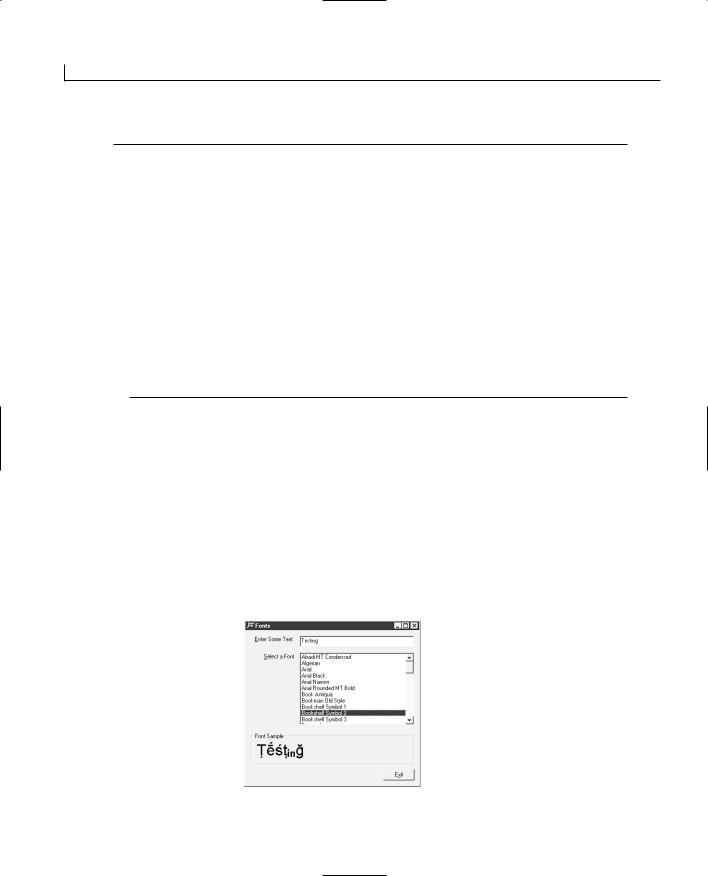
138 |
Day 7 |
LISTING 7.9. THE OnSelchangeLfonts FUNCTION.
1:void CDay7Dlg::OnSelchangeLfonts()
2:{
3:// TODO: Add your control notification handler code here
5:///////////////////////
6:// MY CODE STARTS HERE
7:///////////////////////
9:// Update the variables with the dialog controls
10: UpdateData(TRUE); 11:
12:// Set the font for the sample
13:SetMyFont();
14:
15:///////////////////////
16:// MY CODE ENDS HERE
17:///////////////////////
18:}
In the SetMyFont function, you first checked to make sure that a font had been selected. Next, you retrieved the area of the static text control that will be used to display the font. This enables you to specify a font height just slightly smaller than the height of the area you have available to display the font in. After you calculated the height of the static text control and made sure that it is a positive value, you created the selected font and told the static text control to use the newly created font.
In the OnSelchangeLfonts function, you copy the control values to the attached variables and then call the SetMyFont function to use the selected font. If you compile and run your application, you should be able to select a font and see it displayed in the sample static text control, as in Figure 7.3.
FIGURE 7.3.
Displaying the selected font.

Working with Text and Fonts |
139 |
Summary
Today you learned how to use fonts in Visual C++ applications. You learned how to get a list of the available fonts that are loaded on the system and then how to create a font for use on a display object. You learned how you can create and use callback functions to get a list of resources from the Windows operating system. You also learned how you can access controls from the callback function using a window pointer that you passed to the function requesting the resource list.
Q&A
QThe CreateFont function has a lot of arguments to specify and pass. Is there any other alternative to using this function?
AYes, there is, although you still specify all of the same information. A structure called LOGFONT contains all the same attributes that are passed to the CreateFont function. You can declare an instance of this structure, initializing the attributes to default values, and then pass this structure to the CreateFontIndirect function. If you make numerous font changes, this approach is preferable because you could use the same instance of the structure, modifying those attributes that are changing from the current settings and using it to create the various fonts.
The way that you use this alternative way of creating the font is to declare an instance of the LOGFONT structure as a member of the dialog class and then initialize all the attributes before calling the SetMyFont function. In the SetMyFont function, you modify it as shown in Listing 7.10.
LISTING 7.10. THE MODIFIED SetMyFont FUNCTION.
1:void CDay7Dlg::SetMyFont()
2:{
3:
4:// Has a font been selected?
5:if (m_strFontName != “”)
6:{
7:// Assume that the font size has already been initialized in the
8:// m_lLogFont structure. This allows you to only have to specify
9: |
// the font name. |
7 |
|
10:tcscpy(m_lLogFont.lfFaceName, m_strFontName);
11:// Create the font to be used
12:m_fSampFont.CreateFontIndirect(&m_lLogFont);
14:// Set the font for the sample display area
15:m_ctlDisplayText.SetFont(&m_fSampFont);

140 |
Day 7 |
16:}
17:}
Q How can I limit the fonts in my list to just the TrueType fonts?
AYou can check the nFontType argument to your callback function to determine the font type. For instance, if you want to include only TrueType fonts in your list of fonts, you modify your callback function to mask the nFontType argument with the TRUETYPE_FONTTYPE constant and check to see if the resulting value equals the TRUETYPE_FONTTYPE value, as in the following:
int CALLBACK EnumFontFamProc(LPENUMLOGFONT lpelf, LPNEWTEXTMETRIC lpntm, DWORD nFontType, long lParam)
{
//Create a pointer to the dialog window CDay7Dlg* pWnd = (CDay7Dlg*) lParam;
//Limit the list to TrueType fonts
if ((nFontType & TRUETYPE_FONTTYPE) == TRUETYPE_FONTTYPE)
{
// Add the font name to the list box pWnd->m_ctlFontList.AddString(
lpelf->elfLogFont.lfFaceName);
}
// Return 1 to continue font enumeration return 1;
}
Workshop
The Workshop provides quiz questions to help you solidify your understanding of the material covered and exercises to provide you with experience in using what you’ve learned. The answers to the quiz questions and exercises are provided in Appendix B, “Answers.”
Quiz
1.How can you specify that the text is to be underlined?
2.How can you print your text upside down?
3.How many times is the EnumFontFamProc callback function called by the operating system?
Working with Text and Fonts |
141 |
FIGURE 7.4. |
|
|
Exercises |
Displaying the selected |
|
|
1. Add a check box to switch between using the entered text to display the font and |
font with the font |
|
name. |
using the font name to display the font, as in Figure 7.4. |
|
|
FIGURE 7.5.
Displaying the selected
font in italics2. .Add a check box to display the font sample in italics, as in Figure 7.5.
7


WEEK 1
In Review
Well, you’ve made it through the first week. By this point, you’ve gotten a good taste for what’s possible when building applications with Visual C++. Now it’s time to look back over what’s been covered and what you should have learned up to this point.
What you might want to do at this point, to cement your understanding of how you can use these elements in your own applications, is to try designing and building a couple of simple applications of your own. You can use a variety of controls and add some additional dialogs, just so you can make sure that you do understand and are comfortable with these topics. In fact, you might want to try out all the topics that I’ve covered up to this point in small applications of your own design. That’s the true test of your understanding of how the concepts work. You might also want to dive into the MFC documentation to learn a little about some of the more advanced functionality that I haven’t covered to see if you can figure out how you can use and incorporate it into your applications.
One of the most important things that you should understand at this point is how you can use controls and dialog windows in your applications to get and display information to the user. This is an important part of any Windows application because just about every application interacts with the user in some way. You should be able to place any of the standard controls on a dialog in your application and be able to incorporate them into your application without any problem. Likewise, you should be comfortable with using the standard message box and dialog windows provided to your application by the Windows operating system. You should also be
1
2
3
4
5
6
7
|
144 |
Week 1 |
|
able to create and incorporate your own custom dialog windows into any application you might want to build. If you don’t feel comfortable with any of these topics, you might want to go back and review Day 2 to get a better understanding of how you can use controls and Day 5 to understand how you can incorporate standard and custom dialog windows into your applications.
Another key skill that you will be using in the majority of your applications is the ability to build and incorporate menus into your applications. You need to have a firm understanding of how to design a good menu, how to make sure that there are no conflicting mnemonics, and how you can attach application functionality to the menu selections. At this point, you should be able to create your own customized menus, with entries for each of the various functions that your application performs, and integrate it with your application with no problems. If you aren’t 100% comfortable with this topic, you might want to go back and study Day 6 a little more.
You will find that there are various situations in which you need to have some means of triggering actions on a regular basis or in which you need to keep track of how long some process has been running. For both of these situations, as well as numerous others, you’ll often find yourself turning to the use of timers in your application. If you are even slightly foggy on how you can integrate timers into your applications, you will definitely want to go back and review Day 4.
Understanding how you can use text and fonts in your applications will allow you to build more flexibility into the appearance of your applications—to give your users the ability to customize the appearance as they want. You will be able to examine the available fonts on the computer on which your application is running and, if a font that you want to use in your application isn’t available, choose another font that is close to use instead. If you still have any questions on how the font infrastructure in Windows works and how you can use it in your applications, you’ll want to go back and review Day 7 once more.
Depending on the nature of your application, being able to capture and track mouse and keyboard actions by the user can be very important. If you are building a drawing application, this is crucial information. If you are building an application that needs to include drag-and-drop capabilities, this is important once again. There are any number of situations in which you’ll want to include this functionality into your applications. By this point, you should understand how you can capture the various mouse events and determine which mouse buttons are involved in the event. You should also be able to capture keyboard events in situations where the keyboard input isn’t captured by any controls that are on the window. If you don’t feel like you have a complete grasp of this, you should take another look at Day 3.
In Review |
145 |
|
|
Finally, you should be familiar with the Visual C++ development environment, the Developer Studio. You should have a good understanding of what each area of the environment is for and how you can use the various tools and utilities in building your applications. You should be comfortable with using the workspace pane to navigate around your application project, locating and bringing into the various editors and designers any part of your application. You should be comfortable with locating and redesigning the icon that will be displayed to represent your application and with finding any member functions or variables in any of your application’s classes.
By now you should be getting fairly comfortable working with Visual C++. If you feel like you understand all the topics that I’ve covered so far, you are ready to continue forward, learning more about the various things that you can do, and functionality that you can build, using Visual C++ as your programming tool. With that said, it’s on to the second week…


WEEK 2
At a Glance
In the second week, you’ll dive into several more involved topics. These topics are still very much core to building Windows applications. You’ll find yourself using what you learn in this week, along with what you learned during the first week, in just about all the applications that you build with Visual C++.
To start the week, on Day 8, you’ll learn how to draw graphics in a Windows application. You’ll learn how to draw simple lines, rectangles, and ellipses. What’s more important—you’ll learn about the device context and how you can use it to draw your graphics without worrying
about the graphics hardware your users might or might not have in their computers.
On Day 9, you’ll learn how easy it is to incorporate ActiveX controls into your applications. You’ll see how Visual C++ builds custom C++ classes around the controls that you add to your project, enabling you to interact with an added control just as if it were another C++ object.
On Day 10, you’ll learn how to build a basic Single Document Interface (SDI) application. You’ll learn about the Document/View architecture that is used with Visual C++ for building this style of application, and you’ll learn how you can use it to build your own applications.
On Day 11, you’ll learn how you can apply what you learned about building SDI applications to building Multiple Document Interface (MDI) applications. You’ll see how you can use the same Document/View architecture to create MDI applications, some of the most common style of Windows applications available today.
8
9
10
11
12
13
14

148 |
Week 2 |
On Day 12, you’ll learn how you can create and modify your own toolbars and status bars. You’ll learn how you can attach toolbar buttons to menus in your application and how you can add additional toolbars. You’ll also learn how you can place your own informational elements on the status bar at the bottom of most Windows applications and how you can keep the status bar updated with the status of your application.
On Day 13, you’ll see how you can use the structure provided for you by the Document/View architecture to save and restore the data created in your application. You’ll learn how flexible this facility is and how you can store different data types in the same file, restoring them to your application just as they were when you first saved them.
Finally, rounding out the week on Day 14, you’ll learn how easy it is to build a database application with an ODBC database. You’ll learn how to query a set of records from the database and how to allow the user to edit and modify them, saving the changes back to the database.
When you finish this week, you’ll be well prepared for tackling most basic application development tasks with Visual C++. You might want to take a short break at that point to experiment a bit—trying to build various types of applications, pushing your skills, and learning what your limits are (and aren’t)—before jumping into the final week of more advanced topics.
WEEK 2
DAY 8
Adding Flash—
Incorporating Graphics,
Drawing, and Bitmaps
You’ve probably noticed that a large number of applications use graphics and display images. This adds a certain level of flash and polish to the application. With some applications, graphics are an integral part of their functionality. Having a good understanding of what’s involved in adding these capabilities to your applications is a key part of programming for the Windows platform. You’ve already learned how you can draw lines and how you can string a series of these lines together to make a continuous drawing. Today, you’re going to go beyond that capacity and learn how you can add more advanced graphics capabilities to your applications. Today, you will learn
•How Windows uses a device context to translate drawing instructions into graphics output.
•How you can determine the level of control you have over the graphics output through different mapping modes.

150 |
Day 8 |
•How Windows uses pens and brushes to draw different portions of the graphics image.
•How you can load and display bitmaps dynamically.
Understanding the Graphics Device Interface
The Windows operating system provides you with a couple of levels of abstraction for creating and using graphics in your applications. During the days of DOS programming, you needed to exercise a great deal of control over the graphics hardware to draw any kind of images in an application. This control required an extensive knowledge and understanding of the various types of graphics cards that users might have in their computers, along with their options for monitors and resolutions. There were a few graphics libraries that you could buy for your applications, but overall, it was fairly strenuous programming to add this capability to your applications.
With Windows, Microsoft has made the job much easier. First, Microsoft provides you with a virtual graphics device for all of your Windows applications. This virtual device doesn’t change with the hardware but remains the same for all possible graphics hardware that the user might have. This consistency provides you with the ability to create whatever kind of graphics you want in your applications because you know that the task of converting them to something that the hardware understands isn’t your problem.
Device Contexts
Before you can create any graphics, you must have the device context in which the graphics will be displayed. The device context contains information about the system, the application, and the window in which you are drawing any graphics. The operating system uses the device context to learn in which context a graphic is being drawn, how much of the area is visible, and where on the screen it is currently located.
When you draw graphics, you always draw them in the context of an application window. At any time, this window may be full view, minimized, partly hidden, or completely hidden. This status is not your concern because you draw your graphics on the window using its device context. Windows keeps track of each device context and uses it to determine how much and what part of the graphics you draw to actually display for the user. In essence, the device context you use to display your graphics is the visual context of the window in which you draw them.
The device context uses two resources to perform most of its drawing and graphics functions. These two resources are pens and brushes. Much like their real-world counterparts, pens and brushes perform similar yet different tasks. The device context uses pens to
Adding Flash—Incorporating Graphics, Drawing, and Bitmaps |
151 |
draw lines and shapes, whereas brushes paint areas of the screen. It’s the same idea as
working on paper when you use a pen to draw an outline of an image and then pick up a 8 paintbrush to fill in the color between the lines.
The Device Context Class
In Visual C++, the MFC device context class (CDC) provides numerous drawing functions for drawing circles, squares, lines, curves, and so on. All these functions are part of the device context class because they all use the device context information to draw on your application windows.
You create a device context class instance with a pointer to the window class that you want to associate with the device context. This allows the device context class to place all of the code associated with allocating and freeing a device context in the class constructor and destructors.
Note
Device context objects, as well as all of the various drawing objects, are classified as resources in the Windows operating system. The operating system has only a limited amount of these resources. Although the total number of resources is large in recent versions of Windows, it is still possible to run out of resources if an application allocates them and doesn’t free them correctly. This loss is known as a resource leak, and much like a memory leak, it can eventually lock up a user’s system. As a result, it’s advisable to create these resources in the functions where they will be used and then delete them as soon as you are finished with them.
Following this advised approach to using device contexts and their drawing resources, you use them almost exclusively as local variables within a single function. The only real exception is when the device context object is created by Windows and passed into the event-processing function as an argument.
The Pen Class
You have already seen how you can use the pen class, CPen, to specify the color and width for drawing lines onscreen. CPen is the primary resource tool for drawing any kind of line onscreen. When you create an instance of the CPen class, you can specify the line type, color, and thickness. After you create a pen, you can select it as the current drawing tool for the device context so that it is used for all of your drawing commands to the
152 |
Day 8 |
device context. To create a new pen, and then select it as the current drawing pen, you use the following code:
//Create the device context CDC dc(this);
//Create the pen
CPen lPen(PS_SOLID, 1, RGB(0, 0, 0));
// Select the pen as the current drawing pen dc.SelectObject(&lPen);
You can use a number of different pen styles. These pen styles all draw different patterns when drawing lines. Figure 8.1 shows the basic styles that can be used in your applications with any color.
FIGURE 8.1.
Windows pen styles.
Note
PS_SOLID
PS_DOT
PS_DASH
PS_DASDOT
PS_DASHDOTDOT
PS_NULL
PS_INSIDEFRAME
When you use any of these line styles with a pen thickness greater than 1, all of the lines appear as solid lines. If you want to use any line style other than PS_SOLID, you need to use a pen width of 1.
Along with the line style that the pen should draw, you also have to specify the pen’s width and color. The combination of these three variables specifies the appearance of the resulting lines. The line width can range from 1 on up, although when you reach a width of 32, it’s difficult to exercise any level of precision in your drawing efforts.
You specify the color as a RGB value, which has three separate values for the brightness of the red, green, and blue color components of the pixels on the computer screen. These three separate values can range from 0 to 255, and the RGB function combines them into a single value in the format needed by Windows. Some of the more common colors are listed in Table 8.1.

Adding Flash—Incorporating Graphics, Drawing, and Bitmaps |
153 |
TABLE 8.1. COMMON WINDOWS COLORS. |
|
|
|
|
||
|
Color |
Red |
Green |
Blue |
8 |
|
|
Black |
0 |
0 |
0 |
|
|
|
Blue |
0 |
0 |
255 |
|
|
|
Dark blue |
0 |
0 |
128 |
|
|
|
Green |
0 |
255 |
0 |
|
|
|
Dark green |
0 |
128 |
0 |
|
|
|
Cyan |
0 |
255 |
255 |
|
|
|
Dark cyan |
0 |
128 |
128 |
|
|
|
Red |
255 |
0 |
0 |
|
|
|
Dark red |
128 |
0 |
0 |
|
|
|
Magenta |
255 |
0 |
255 |
|
|
|
Dark magenta |
128 |
0 |
128 |
|
|
|
Yellow |
255 |
255 |
0 |
|
|
|
Dark yellow |
128 |
128 |
0 |
|
|
|
Dark gray |
128 |
128 |
128 |
|
|
|
Light gray |
192 |
192 |
192 |
|
|
|
White |
255 |
255 |
255 |
|
|
|
|
|
|
|
|
|
The Brush Class
The brush class, CBrush, allows you to create brushes that define how areas will be filled in. When you draw shapes that enclose an area and fill in the enclosed area, the outline is drawn with the current pen, and the interior of the area is filled by the current brush.
Brushes can be solid colors (specified using the same RGB values as with the pens), a pattern of lines, or even a repeated pattern created from a small bitmap. If you want to create a solid-color brush, you need to specify the color to use:
CBrush lSolidBrush(RGB(255, 0, 0));
To create a pattern brush, you need to specify not only the color but also the pattern to use:
CBrush lPatternBrush(HS_BDIAGONAL, RGB(0, 0, 255));
After you create a brush, you can select it with the device context object, just like you do with pens. When you select a brush, it is used as the current brush whenever you draw something that uses a brush.
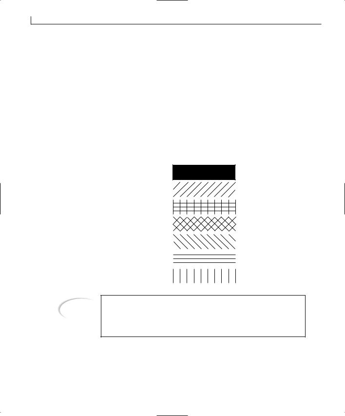
154 |
Day 8 |
As with pens, you can select a number of standard patterns when creating a brush, as shown in Figure 8.2. In addition to these patterns, an additional style of brush, HS_BITMAP, uses a bitmap as the pattern for filling the specified area. This bitmap is limited in size to 8 pixels by 8 pixels, which is a smaller bitmap than normally used for toolbars and other small images. If you supply it with a larger bitmap, it takes only the upper-left corner, limiting it to an 8-by-8 square. You can create a bitmap brush by creating a bitmap resource for your application and assigning it an object ID. After you do this, you can create a brush with it by using the following code:
CBitmap m_bmpBitmap;
// Load the image m_bmpBitmap.LoadBitmap(IDB_MYBITMAP); // Create the brush
CBrush lBitmapBrush(&m_bmpBitmap);
FIGURE 8.2.
Standard brush patterns.
Tip
HS_SOLID
HS_BDIAGONAL
HS_CROSS
HS_DIAGCROSS
HS_FDIAGONAL
HS_HORIZONTAL
HS_VERTICAL
If you want to create your own custom pattern for use as a brush, you can create the pattern as an 8-by-8 bitmap and use the bitmap brush. This allows you to extend the number of brush patterns far beyond the limited number of standard patterns.
The Bitmap Class
When you want to display images in your applications, you have a couple of options. You can add fixed bitmaps to your application, as resources with object IDs assigned to

Adding Flash—Incorporating Graphics, Drawing, and Bitmaps |
155 |
them and use static picture controls or an ActiveX control that displays images. You can |
|
|
also use the bitmap class, CBitmap, to exercise complete control over the image display. |
8 |
|
If you use the bitmap class, you can dynamically load bitmap images from files on the |
||
|
||
system disk, resizing the images as necessary to make them fit in the space you’ve |
|
|
allotted. |
|
|
If you add the bitmap as a resource, you can create an instance of the CBitmap class using |
|
|
|
||
the resource ID of the bitmap as the image to be loaded. If you want to load a bitmap |
|
|
from a file, you can use the LoadImage API call to load the bitmap from the file. After |
|
|
you load the bitmap, you can use the handle for the image to attach the image to the |
|
|
CBitmap class, as follows: |
|
|
// Load the bitmap file |
|
|
HBITMAP hBitmap = (HBITMAP)::LoadImage(AfxGetInstanceHandle(), |
|
|
m_sFileName, IMAGE_BITMAP, 0, 0, |
|
|
LR_LOADFROMFILE | LR_CREATEDIBSECTION); |
|
|
// Attach the loaded image to the CBitmap object. |
|
|
m_bmpBitmap.Attach(hBitmap); |
|
|
After you load the bitmap into the CBitmap object, you can create a second device con- |
|
|
text and select the bitmap into it. When you’ve created the second device context, you |
|
|
need to make it compatible with the primary device context before the bitmap is selected |
|
|
into it. Because device contexts are created by the operating system for a specific output |
|
|
device (screen, printer, and so on), you have to make sure that the second device context |
|
|
is also attached to the same output device as the first. |
|
|
// Create a device context |
|
|
CDC dcMem; |
|
|
// Make the new device context compatible with the real DC |
|
|
dcMem.CreateCompatibleDC(dc); |
|
|
// Select the bitmap into the new DC |
|
|
dcMem.SelectObject(&m_bmpBitmap); |
|
|
When you select the bitmap into a compatible device context, you can copy the bitmap |
|
|
into the regular display device context using the BitBlt function: |
|
|
// Copy the bitmap to the display DC |
|
|
dc->BitBlt(10, 10, bm.bmWidth, |
|
|
bm.bmHeight, &dcMem, 0, 0, |
|
|
SRCCOPY); |
|
|
You can also copy and resize the image using the StretchBlt function: |
|
|
// Resize the bitmap while copying it to the display DC |
|
|
dc->StretchBlt(10, 10, (lRect.Width() - 20), |
|
|
(lRect.Height() - 20), &dcMem, 0, 0, |
|
|
bm.bmWidth, bm.bmHeight, SRCCOPY); |
|

156 |
Day 8 |
By using the StretchBlt function, you can resize the bitmap so that it will fit in any area on the screen.
Mapping Modes and Coordinate Systems
When you are preparing to draw some graphics on a window, you can exercise a lot of control over the scale you are using and the area in which you can draw. You can control these factors by specifying the mapping mode and the drawing area.
By specifying the mapping mode, you can control how the coordinates that you specify are translated into locations on the screen. The different mapping modes translate each point into a different distance. You can set the mapping mode by using the SetMapMode device context function:
dc->SetMapMode(MM_ANSIOTROPIC);
The available mapping modes are listed in Table 8.2.
TABLE 8.2. MAPPING MODES.
Mode |
Description |
MM_ANSIOTROPIC MM_HIENGLISH
MM_HIMETRIC
MM_ISOTROPIC
MM_LOENGLISH
MM_LOMETRIC
MM_TEXT
MM_TWIPS
Logical units are converted into arbitrary units with arbitrary axes.
Each logical unit is converted into 0.001 inch. Positive x is to the right, and positive y is up.
Each logical unit is converted into 0.01 millimeter. Positive x is to the right, and positive y is up.
Logical units are converted into arbitrary units with equally scaled axes.
Each logical unit is converted into 0.01 inch. Positive x is to the right, and positive y is up.
Each logical unit is converted into 0.1 millimeter. Positive x is to the right, and positive y is up.
Each logical unit is converted into 1 pixel. Positive x is to the right, and positive y is down.
Each logical unit is converted into 1/20 of a point (approximately 1/1440 inch). Positive x is to the right, and positive y is up.
If you use either the MM_ANSIOTROPIC or MM_ISOTROPIC mapping modes, you can use either the SetWindowExt or SetViewportExt functions to specify the drawing area where your graphics should appear.

Adding Flash—Incorporating Graphics, Drawing, and Bitmaps |
157 |
Creating a Graphics Application
To get a good understanding of how you can put all of this information to use, you’ll |
8 |
build an application that incorporates a lot of what I’ve covered so far today. This application will have two independent windows, one with a number of options to choose for the shape, tool, and color to be displayed. The other window will act as a canvas, where all of the selected options will be drawn. The user can select whether to display lines, squares, circles, or a bitmap on the second window. The user can also specify the color and choose whether to display the pen or brush for the circles and squares.
Generating the Application Shell
As you have learned by now, the first step in building an application is generating the initial application shell. This shell provides the basic application functionality, displaying your first application dialog, along with all startup and shutdown functionality.
For the application that you will build today, you need to start with a standard dialogstyle application shell. You can create this for your application by starting a new AppWizard project, providing a suitable project name, such as Graphics. After you are in the AppWizard, specify that you are creating a dialog-style application. At this point, you can accept all of the default settings, although you won’t need ActiveX support, and you can specify a more descriptive window title if you want.
Designing the Main Dialog
After you make your way through the AppWizard, you’re ready to start designing your primary dialog. This window will contain three groups of radio buttons: one group for specifying the drawing tool, the next to specify the drawing shape, and the third to specify the color. Along with these groups of radio buttons, you’ll have two buttons on the window: one to open a File Open dialog, for selecting a bitmap to be displayed, and the other to close the application.
To add all these controls to your dialog, lay them out as shown in Figure 8.3 and specify the control properties listed in Table 8.3.
158 |
Day 8 |
FIGURE 8.3.
The main dialog layout.
TABLE 8.3. CONTROL PROPERTY SETTINGS.
Object |
Property |
Setting |
Group Box |
ID |
|
Caption |
Radio Button |
ID |
|
Caption |
|
Group |
Radio Button |
ID |
|
Caption |
Radio Button |
ID |
|
Caption |
Group Box |
ID |
|
Caption |
Radio Button |
ID |
|
Caption |
|
Group |
Radio Button |
ID |
|
Caption |
IDC_STATIC
Drawing Tool IDC_RTPEN &Pen Checked IDC_RTBRUSH &Brush IDC_RTBITMAP B&itmap IDC_STATIC Drawing Shape IDC_RSLINE &Line Checked IDC_RSCIRCLE &Circle

Adding Flash—Incorporating Graphics, Drawing, and Bitmaps |
159 |
Object |
Property |
Setting |
Radio Button |
ID |
|
Caption |
Group Box |
ID |
|
Caption |
Radio Button |
ID |
|
Caption |
|
Group |
Radio Button |
ID |
|
Caption |
Radio Button |
ID |
|
Caption |
Radio Button |
ID |
|
Caption |
Radio Button |
ID |
|
Caption |
Radio Button |
ID |
|
Caption |
Radio Button |
ID |
|
Caption |
Radio Button |
ID |
|
Caption |
Command Button |
ID |
|
Caption |
Command Button |
ID |
|
Caption |
IDC_RSSQUARE |
8 |
|
|
&Square |
|
IDC_STATIC |
|
Color |
|
IDC_RCBLACK |
|
Bl&ack |
|
Checked |
|
IDC_RCBLUE |
|
Bl&ue |
|
IDC_RCGREEN |
|
&Green |
|
IDC_RCCYAN |
|
Cya&n |
|
IDC_RCRED |
|
&Red |
|
IDC_RCMAGENTA |
|
&Magenta |
|
IDC_RCYELLOW |
|
&Yellow |
|
IDC_RCWHITE |
|
&White |
|
IDC_BBITMAP |
|
Bi&tmap |
|
IDC_BEXIT |
|
E&xit |
|
When you finish designing your main dialog, you need to assign one variable to each of the groups of radio buttons. To do this, open the Class Wizard and assign one integer variable to each of the three radio button object IDs there. Remember that only the object IDs for the radio buttons with the Group option checked will appear in the Class Wizard. All of the radio buttons that follow will be assigned to the same variable, with sequential values, in the order of the object ID values. For this reason, it is important to create all of the radio buttons in each group in the order that you want their values to be sequenced.

160 |
Day 8 |
To assign the necessary variables to the radio button groups in your application, open the Class Wizard and add the variables in Table 8.4 to the objects in your dialog.
TABLE 8.4. CONTROL VARIABLES.
Object |
Name |
Category |
Type |
IDC_RTPEN |
m_iTool |
Value |
int |
IDC_RSLINE |
m_iShape |
Value |
int |
IDC_RCBLACK |
m_iColor |
Value |
int |
|
|
|
|
While you have the Class Wizard open, you might want to switch back to the first tab and add an event-handler function to the Exit button, calling the OnOK function in the code for this button. You can compile and run your application now, making sure that you have all of the radio button groups defined correctly, that you can’t select two or more buttons in any one group, and that you can select one button in each group without affecting either of the other two groups.
Adding the Second Dialog
When you design the main dialog, you’ll add the second window that you’ll use as a canvas to paint your graphics on. This dialog will be a modeless dialog, which will remain open the entire time the application is running. You will put no controls on the dialog, providing a clean canvas for drawing.
To create this second dialog, go to the Resources tab in the workspace pane. Right-click the Dialogs folder in the resource tree. Select Insert Dialog from the pop-up menu. When the new dialog is open in the window designer, remove all of the controls from the window. After you remove all of the controls, open the properties dialog for the window and uncheck the System Menu option on the second tab of properties. This will prevent the user from closing this dialog without exiting the application. You’ll also want to give this dialog window an object ID that will describe its function, such as IDD_PAINT_DLG.
After you finish designing the second dialog, create a new class for this window by opening the Class Wizard. When you try to open the Class Wizard, you’ll be asked if you want to create a new class for the second dialog window. Leave this option at its default setting and click the OK button. When asked to specify the name of the new class on the next dialog, give the class a suitable name, such as CPaintDlg, and be sure that the base class is set to CDialog. After you click OK on this dialog and create the new class, you can close the Class Wizard.
Adding Flash—Incorporating Graphics, Drawing, and Bitmaps |
161 |
Note
You need to make sure that the new dialog is selected when you try to open |
|
8 |
the Class Wizard. If the dialog is not selected, and you’ve switched to another |
|
|
object, or even some code in your application, the Class Wizard will not |
|
|
know that you need a class for the second dialog in your application. |
|
|
|
|
|
|
|
|
Now that you have the second dialog defined, you need to add the code in the first dialog window to open the second dialog. You can accomplish this by adding two lines of code to the OnInitDialog function in the first window’s class. First, create the dialog using the Create method of the CDialog class. This function takes two arguments: the object ID of the dialog and a pointer to the parent window, which will be the main dialog. The second function will be the ShowWindow function, passing the value S W _ S H O W as the only argument. This function displays the second dialog next to the first dialog. Add a couple of lines of variable initialization to make your OnInitDialog function resemble Listing 8.1.
LISTING 8.1. THE OnInitDialog FUNCTION.
1:BOOL CGraphicsDlg::OnInitDialog()
2:{
3:CDialog::OnInitDialog();
4:
.
.
.
27:
28: // TODO: Add extra initialization here 29:
30:///////////////////////
31:// MY CODE STARTS HERE
32:///////////////////////
34:// Initialize the variables and update the dialog window
35:m_iColor = 0;
36:m_iShape = 0;
37:m_iTool = 0;
38:UpdateData(FALSE);
39:
40:// Create the second dialog window
41:m_dlgPaint.Create(IDD_PAINT_DLG, this);
42:// Show the second dialog window
43:m_dlgPaint.ShowWindow(SW_SHOW);
continues
162 |
Day 8 |
LISTING 8.1. CONTINUED
44:
45:///////////////////////
46:// MY CODE ENDS HERE
47:///////////////////////
49:return TRUE; // return TRUE unless you set the focus to a control
50:}
Before you can compile and run your application, you’ll need to include the header for the second dialog class in the source code for the first dialog. You’ll also need to add the second dialog class as a variable to the first—which is a simple matter of adding a member variable to the first dialog class, specifying the variable type as the class type, in this case CPaintDlg, giving the variable the name that you used in Listing 8.1, m_dlgPaint, and specifying the variable access as private. To include the header file in the first dialog, scroll to the top of the source code for the first dialog and add an include statement, as in Listing 8.2.
LISTING 8.2. THE INCLUDE STATEMENT OF THE MAIN DIALOG.
1:// GraphicsDlg.cpp : implementation file
2://
3:
4:#include “stdafx.h”
5:#include “Graphics.h”
6:#include “PaintDlg.h”
7:#include “GraphicsDlg.h”
Conversely, you’ll need to include the header file for the main dialog in the source code for the second dialog. You can edit this file, PaintDlg.cpp, making the include statements match those in Listing 8.2.
If you compile and run your application, you should see your second dialog window open along with the first window. What you’ll also noticed is that when you close the first dialog, and thus close the application, the second dialog window also closes, even though you didn’t add any code to make this happen. The second dialog is a child window to the first dialog. When you created the second dialog, on line 41 of the code listing, you passed a pointer to the first dialog window as the parent window for the second window. This set up a parent-child relationship between these two windows. When the

Adding Flash—Incorporating Graphics, Drawing, and Bitmaps |
163 |
parent closes, so does the child. This is the same relationship the first dialog window has
with all of the controls you placed on it. Each of those controls is a child window of the 8 dialog. In a sense, what you’ve done is make the second dialog just another control on
the first dialog.
Adding the Graphics Capabilities
Because all of the radio button variables are declared as public, the second dialog will be able to see and reference them as it needs to. You can place all of the graphic drawing functionality into the second dialog class. However, you do need to place some functionality into the first dialog to keep the variables synchronized and to tell the second dialog to draw its graphics. Accomplishing this is simpler than you might think.
Whenever a window needs to be redrawn (it may have been hidden behind another window and come to the front or minimized or off the visible screen and now in view), the operating system triggers the dialog’s OnPaint function. You can place all the functionality for drawing your graphics in this function and make persistent the graphics you display.
Now that you know where to place your code to display the graphics, how can you cause the second dialog to call its OnPaint function whenever the user changes one of the selections on the first dialog? Well, you could hide and then show the second dialog, but that might look a little peculiar to the user. Actually, a single function will convince the second window that it needs to redraw its entire dialog. This function, Invalidate, requires no arguments and is a member function of the CWnd class, so it can be used on any window or control. The Invalidate function tells the window, and the operating system, that the display area of the window is no longer valid and that it needs to be redrawn. You can trigger the OnPaint function in the second dialog at will, without resorting to any awkward tricks or hacks.
At this point, we have determined that all of the radio buttons can use the same functionality on their clicked events. You can set up a single event-handler function for the clicked event on all of the radio button controls. In this event function, you’ll need to synchronize the class variables with the dialog controls by calling the UpdateData function and then tell the second dialog to redraw itself by calling its Invalidate function. You can write a single event handler that does these two things with the code in Listing 8.3.

164 |
Day 8 |
LISTING 8.3. THE OnRSelection FUNCTION.
1:void CGraphicsDlg::OnRSelection()
2:{
3:// TODO: Add your control notification handler code here
5:// Synchronize the data
6:UpdateData(TRUE);
7:// Repaint the second dialog
8:m_dlgPaint.Invalidate();
9:}
Drawing Lines
You can compile and run your application at this point, and the second dialog redraws itself whenever you choose a different radio button on the main dialog, but you wouldn’t notice anything happening. At this point, you are triggering the redraws, but you haven’t told the second dialog what to draw, which is the next step in building this application.
The easiest graphics to draw on the second dialog will be different styles of lines because you already have some experience drawing them. What you’ll want to do is create one pen for each of the different pen styles, using the currently selected color. After you have created all of the pens, you’ll loop through the different pens, selecting each one in turn and drawing a line across the dialog with each one. Before you start this loop, you need to perform a few calculations to determine where each of the lines should be on the dialog, with their starting and stopping points.
To begin adding this functionality to your application, you first add a color table, with one entry for each of the colors in the group of available colors on the first dialog. To create this color table, add a new member variable to the second dialog class, CPaintDlg, and specify the variable type as static const COLORREF, the name as m_crColors[8], and the access as public. Open the source code file for the second dialog class, and add the color table in Listing 8.4 near the top of the file before the class constructor and destructor.
LISTING 8.4. THE COLOR TABLE.
1: const COLORREF CPaintDlg::m_crColors[8] = {
2: |
RGB( |
0, |
0, |
0), |
// Black |
3: |
RGB( |
0, |
0, 255), |
// Blue |
|
4: |
RGB( |
0, 255, |
0), |
// Green |
|
5: |
RGB( |
0, 255, 255), |
// Cyan |
||
6: |
RGB( 255, |
0, |
0), |
// Red |
|
7: |
RGB( 255, |
0, 255), |
// Magenta |
||
Adding Flash—Incorporating Graphics, Drawing, and Bitmaps |
165 |
8: |
RGB( 255, 255, 0), |
// Yellow |
|
9: |
RGB( 255, 255, 255) |
// White |
8 |
10: }; |
|
|
11:///////////////////////////////////////////////////////////////////
12:// CPaintDlg dialog
.
.
.
With the color table in place, you can add a new function for drawing the lines. To keep the OnPaint function from getting too cluttered and difficult to understand, it makes more sense to place a limited amount of code in it to determine what should be drawn
on the second dialog and then call other more specialized functions to draw the various shapes. With this in mind, you need to create a new member function for the second dialog class for drawing the lines. Declare this as a void function, and specify its declaration as DrawLine(CPaintDC *pdc, int iColor) and its access as private. You can edit this function, adding the code in Listing 8.5.
LISTING 8.5. THE DrawLine FUNCTION.
1:void CPaintDlg::DrawLine(CPaintDC *pdc, int iColor)
2:{
3:// Declare and create the pens
4:CPen lSolidPen (PS_SOLID, 1, m_crColors[iColor]);
5:CPen lDotPen (PS_DOT, 1, m_crColors[iColor]);
6:CPen lDashPen (PS_DASH, 1, m_crColors[iColor]);
7:CPen lDashDotPen (PS_DASHDOT, 1, m_crColors[iColor]);
8:CPen lDashDotDotPen (PS_DASHDOTDOT, 1, m_crColors[iColor]);
9:CPen lNullPen (PS_NULL, 1, m_crColors[iColor]);
10:CPen lInsidePen (PS_INSIDEFRAME, 1, m_crColors[iColor]);
11:
12:// Get the drawing area
13:CRect lRect;
14:GetClientRect(lRect);
15:lRect.NormalizeRect();
17:// Calculate the distance between each of the lines
18:CPoint pStart;
19:CPoint pEnd;
20:int liDist = lRect.Height() / 8;
21:CPen *lOldPen;
22:// Specify the starting points
23:pStart.y = lRect.top;
24:pStart.x = lRect.left;
continues

166 |
Day 8 |
LISTING 8.5. CONTINUED
25:pEnd.y = pStart.y;
26:pEnd.x = lRect.right;
27:int i;
28:// Loop through the different pens
29:for (i = 0; i < 7; i++)
30:{
31:// Which pen are we on?
32:switch (i)
33:{
34:case 0: // Solid
35:lOldPen = pdc->SelectObject(&lSolidPen);
36:break;
37:case 1: // Dot
38:pdc->SelectObject(&lDotPen);
39:break;
40:case 2: // Dash
41:pdc->SelectObject(&lDashPen);
42:break;
43:case 3: // Dash Dot
44:pdc->SelectObject(&lDashDotPen);
45:break;
46:case 4: // Dash Dot Dot
47:pdc->SelectObject(&lDashDotDotPen);
48:break;
49:case 5: // Null
50:pdc->SelectObject(&lNullPen);
51:break;
52:case 6: // Inside
53:pdc->SelectObject(&lInsidePen);
54:break;
55:}
56:// Move down to the next position
57:pStart.y = pStart.y + liDist;
58:pEnd.y = pStart.y;
59:// Draw the line
60:pdc->MoveTo(pStart);
61:pdc->LineTo(pEnd);
62:}
63:// Select the original pen
64:pdc->SelectObject(lOldPen);
65:}
Now you need to edit the OnPaint function so that the OnLine function is called when it needs to be called. Add this function through the Class Wizard as an event-handler function for the WM_PAINT message. You’ll notice that the generated code for this function creates a CPaintDC variable instead of the normal CDC class. The CPaintDC class is a
Adding Flash—Incorporating Graphics, Drawing, and Bitmaps |
167 |
descendent of the CDC device context class. It automatically calls the BeginPaint and
EndPaint API functions that all Windows applications must call before drawing any 8 graphics during the WM_PAINT event message processing. It can be treated just like a reg-
ular device context object, calling all of the same functions.
When you are in the OnPaint function, you need to get a pointer to the parent window so that you can check the values of the variables tied to the groups of radio buttons to determine the color, tools, and shape to be drawn on the second dialog. This information tells you whether to call the DrawLine function or another function that you haven’t written yet.
To add this functionality to your application, add an event handler for the WM_PAINT message on the second dialog class, adding the code in Listing 8.6 to the function created in your class.
LISTING 8.6. THE OnPaint FUNCTION.
1:void CPaintDlg::OnPaint()
2:{
3:CPaintDC dc(this); // device context for painting
5: // TODO: Add your message handler code here 6:
7:// Get a pointer to the parent window
8:CGraphicsDlg *pWnd = (CGraphicsDlg*)GetParent();
9:// Do we have a valid pointer?
10:if (pWnd)
11:{
12:// Is the tool a bitmap?
13:if (pWnd->m_iTool == 2)
14:{
15:}
16: |
else |
// No, we’re drawing a shape |
17:{
18:// Are we drawing a line?
19:if (pWnd->m_iShape == 0)
20:DrawLine(&dc, pWnd->m_iColor);
21:}
22:}
23:// Do not call CDialog::OnPaint() for painting messages
24:}
At this point, if you compile and run your application, you should be able to draw lines across the second dialog, as shown in Figure 8.4.
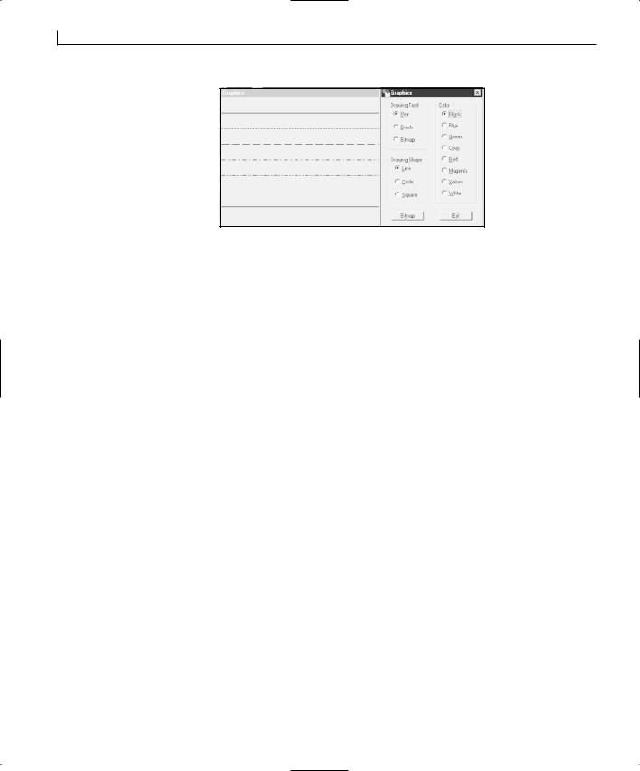
168 |
Day 8 |
FIGURE 8.4.
Drawing lines on the second dialog.
Drawing Circles and Squares
Now that you have the basic structure in place, and you can see how you can change what is drawn on the second dialog at will, you are ready to add code to the second dialog to draw the circles and squares. To draw these figures, you use the Ellipse and Rectangle device context functions. These functions will use the currently selected pen and brush to draw these figures at the specified location. With both functions, you pass a CRect object to specify the rectangle in which to draw the specified figure. The Rectangle function fills the entire space specified, and the Ellipse function draws a circle or ellipse where the middle of each side of the rectangle touches the edge of the ellipse. Because these functions use both the pen and brush, you’ll need to create and select an invisible pen and invisible brush to allow the user to choose either the pen or the brush. For the pen, you can use the null pen for this purpose, but for the brush, you’ll need to create a solid brush the color of the window background (light gray).
When you calculate the position for each of these figures, you need to take a different approach from what you used with the lines. With the lines, you were able to get the height of the window, divide it by 8, and then draw a line at each of the divisions from the left edge to the right edge. With the ellipses and rectangles, you’ll need to divide the dialog window into eight even rectangles. The easiest way to do this is to create two rows of figures with four figures in each row. Leave a little space between each figure so that the user can see the different pens used to outline each figure.
To add this functionality to your application, add a new function to the second dialog class. Specify the function type as void, the declaration as DrawRegion(CPaintDC *pdc, int iColor, int iTool, int iShape), and the access as private. Edit the code in this function, adding the code in Listing 8.7.

Adding Flash—Incorporating Graphics, Drawing, and Bitmaps
LISTING 8.7. THE DrawRegion FUNCTION.
1:void CPaintDlg::DrawRegion(CPaintDC *pdc, int iColor, int iTool, intiShape)
2:{
3:// Declare and create the pens
4:CPen lSolidPen (PS_SOLID, 1, m_crColors[iColor]);
5:CPen lDotPen (PS_DOT, 1, m_crColors[iColor]);
6:CPen lDashPen (PS_DASH, 1, m_crColors[iColor]);
7:CPen lDashDotPen (PS_DASHDOT, 1, m_crColors[iColor]);
8:CPen lDashDotDotPen (PS_DASHDOTDOT, 1, m_crColors[iColor]);
9:CPen lNullPen (PS_NULL, 1, m_crColors[iColor]);
10:CPen lInsidePen (PS_INSIDEFRAME, 1, m_crColors[iColor]);
11:
12:// Declare and create the brushes
13:CBrush lSolidBrush(m_crColors[iColor]);
14:CBrush lBDiagBrush(HS_BDIAGONAL, m_crColors[iColor]);
15:CBrush lCrossBrush(HS_CROSS, m_crColors[iColor]);
16:CBrush lDiagCrossBrush(HS_DIAGCROSS, m_crColors[iColor]);
17:CBrush lFDiagBrush(HS_FDIAGONAL, m_crColors[iColor]);
18:CBrush lHorizBrush(HS_HORIZONTAL, m_crColors[iColor]);
19:CBrush lVertBrush(HS_VERTICAL, m_crColors[iColor]);
20:CBrush lNullBrush(RGB(192, 192, 192));
21:
22:// Calculate the size of the drawing regions
23:CRect lRect;
24:GetClientRect(lRect);
25:lRect.NormalizeRect();
26:int liVert = lRect.Height() / 2;
27:int liHeight = liVert - 10;
28:int liHorz = lRect.Width() / 4;
29:int liWidth = liHorz - 10;
30:CRect lDrawRect;
31:CPen *lOldPen;
32:CBrush *lOldBrush;
33:int i;
34:// Loop through all of the brushes and pens
35:for (i = 0; i < 7; i++)
36:{
37:switch (i)
38:{
39:case 0: // Solid
40:// Determine the location for this figure.
41:// Start the first row
42:lDrawRect.top = lRect.top + 5;
43:lDrawRect.left = lRect.left + 5;
44:lDrawRect.bottom = lDrawRect.top + liHeight;
45:lDrawRect.right = lDrawRect.left + liWidth;
46:// Select the appropriate pen and brush
169
8

170 |
Day 8 |
continues
LISTING 8.7. CONTINUED
47:lOldPen = pdc->SelectObject(&lSolidPen);
48:lOldBrush = pdc->SelectObject(&lSolidBrush);
49:break;
50:case 1: // Dot - Back Diagonal
51:// Determine the location for this figure.
52:lDrawRect.left = lDrawRect.left + liHorz;
53:lDrawRect.right = lDrawRect.left + liWidth;
54:// Select the appropriate pen and brush
55:pdc->SelectObject(&lDotPen);
56:pdc->SelectObject(&lBDiagBrush);
57:break;
58:case 2: // Dash - Cross Brush
59:// Determine the location for this figure.
60:lDrawRect.left = lDrawRect.left + liHorz;
61:lDrawRect.right = lDrawRect.left + liWidth;
62:// Select the appropriate pen and brush
63:pdc->SelectObject(&lDashPen);
64:pdc->SelectObject(&lCrossBrush);
65:break;
66:case 3: // Dash Dot - Diagonal Cross
67:// Determine the location for this figure.
68:lDrawRect.left = lDrawRect.left + liHorz;
69:lDrawRect.right = lDrawRect.left + liWidth;
70:// Select the appropriate pen and brush
71:pdc->SelectObject(&lDashDotPen);
72:pdc->SelectObject(&lDiagCrossBrush);
73:break;
74:case 4: // Dash Dot Dot - Forward Diagonal
75:// Determine the location for this figure.
76:// Start the second row
77:lDrawRect.top = lDrawRect.top + liVert;
78:lDrawRect.left = lRect.left + 5;
79:lDrawRect.bottom = lDrawRect.top + liHeight;
80:lDrawRect.right = lDrawRect.left + liWidth;
81:// Select the appropriate pen and brush
82:pdc->SelectObject(&lDashDotDotPen);
83:pdc->SelectObject(&lFDiagBrush);
84:break;
85:case 5: // Null - Horizontal
86:// Determine the location for this figure.
87:lDrawRect.left = lDrawRect.left + liHorz;
88:lDrawRect.right = lDrawRect.left + liWidth;
89:// Select the appropriate pen and brush
90:pdc->SelectObject(&lNullPen);
91:pdc->SelectObject(&lHorizBrush);
92:break;
Adding Flash—Incorporating Graphics, Drawing, and Bitmaps |
171 |
93: |
case 6: |
// Inside - Vertical |
|
94: |
// Determine the location for this figure. |
8 |
|
95: |
lDrawRect.left = lDrawRect.left + liHorz; |
||
96:lDrawRect.right = lDrawRect.left + liWidth;
97:// Select the appropriate pen and brush
98:pdc->SelectObject(&lInsidePen);
99:pdc->SelectObject(&lVertBrush);
100:break;
101:}
102:// Which tool are we using?
103:if (iTool == 0)
104:pdc->SelectObject(lNullBrush);
105:else
106:pdc->SelectObject(lNullPen);
107:// Which shape are we drawing?
108:if (iShape == 1)
109:pdc->Ellipse(lDrawRect);
110:else
111:pdc->Rectangle(lDrawRect);
112:}
113:// Reset the original brush and pen
114:pdc->SelectObject(lOldBrush);
115:pdc->SelectObject(lOldPen);
116:}
Now that you have the capability to draw the circles and squares in the second dialog, you’ll need to call this function when the user has selected either of these two figures with either a pen or a brush. To do this, add the two lines starting at line 21 in Listing 8.8 to the OnPaint function.
LISTING 8.8. THE MODIFIED OnPaint FUNCTION.
1:void CPaintDlg::OnPaint()
2:{
3:CPaintDC dc(this); // device context for painting
5: // TODO: Add your message handler code here 6:
7:// Get a pointer to the parent window
8:CGraphicsDlg *pWnd = (CGraphicsDlg*)GetParent();
9:// Do we have a valid pointer?
10:if (pWnd)
11:{
12:// Is the tool a bitmap?
13:if (pWnd->m_iTool == 2)
14:{
15:}
16: |
else |
// No, we’re drawing a shape |
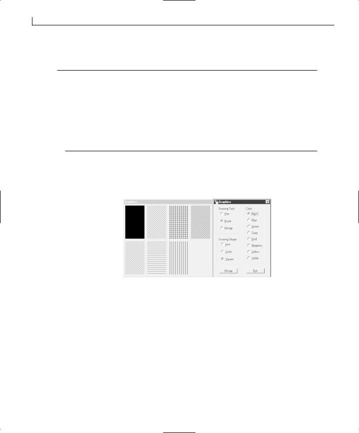
172 |
Day 8 |
continues
LISTING 8.8. CONTINUED
17:{
18:// Are we drawing a line?
19:if (m_iShape == 0)
20:DrawLine(&dc, pWnd->m_iColor);
21: |
else |
// We’re drawing a ellipse or rectangle |
22:DrawRegion(&dc, pWnd->m_iColor, pWnd->m_iTool,pWnd->m_iShape);
23:}
24:}
25:// Do not call CDialog::OnPaint() for painting messages
26:}
Now you should be able to compile and run your application and display not only lines, but also squares and circles, switching between displaying the outlines and the filled-in
figure without any outline, as shown in Figure 8.5.
FIGURE 8.5.
Drawing rectangles on the second dialog.
Loading Bitmaps
Now that you can draw various graphic images on the second dialog window, all that’s left is to add the functionality to load and display bitmaps. You could easily add the bitmaps to the resources in the application, give them their own object IDs, and then use the LoadBitmap and MAKEINTRESOURCE functions to load the bitmap into a CBitmap class object, but that isn’t extremely useful when you start building your own applications. What would be really useful is the ability to load bitmaps from files on the computer disk. To provide this functionality, you use the LoadImage API function to load the bitmap images into memory and then attach the loaded image to the CBitmap object.
To do this in your application, you can attach a function to the bitmap button on the first dialog that displays the File Open dialog to the user, allowing the user to select a bitmap

Adding Flash—Incorporating Graphics, Drawing, and Bitmaps |
173 |
|
to be displayed. You’ll want to build a filter for the dialog, limiting the available files to |
|
|||
|
bitmaps that can be displayed in the second dialog. After the user selects a bitmap, you’ll |
8 |
|||
|
get the file and path name from the dialog and load the bitmap using the LoadImage func- |
||||
|
|
||||
|
tion. When you have a valid handle to the bitmap that was loaded into memory, you’ll |
|
|||
|
delete the current bitmap image from the CBitmap object. If there was a bitmap loaded |
|
|||
|
into the CBitmap object, you’ll detach the CBitmap object from the now deleted image. |
|
|||
|
|||||
|
After you make sure that there isn’t already an image loaded in the CBitmap object, you |
|
|||
|
attach the image you just loaded into memory, using the Attach function. At this point, |
|
|||
|
you want to invalidate the second dialog so that if it’s displaying a bitmap, it displays the |
|
|||
|
newly loaded bitmap. |
|
|
|
|
|
To support this functionality, you need to add a string variable to hold the bitmap name, |
|
|||
|
and a CBitmap variable to hold the bitmap image, to the first dialog class. Add these two |
|
|||
|
variables as listed in Table 8.5. |
|
|
|
|
TABLE 8.5. BITMAP VARIABLES. |
|
|
|
|
|
|
|
|
|
|
|
|
Name |
Type |
Access |
|
|
|
|
|
|
|
|
|
m_sBitmap |
CString |
Public |
|
|
|
m_bmpBitmap |
CBitmap |
Public |
|
|
|
|
|
|
|
|
After you add the variables to the first dialog class, add an event-handler function to the clicked event of the Bitmap button using the Class Wizard. After you add this function, edit it, adding the code in Listing 8.9.
LISTING 8.9. THE OnBbitmap FUNCTION.
1:void CGraphicsDlg::OnBbitmap()
2:{
3:// TODO: Add your control notification handler code here
5:// Build a filter for use in the File Open dialog
6:static char BASED_CODE szFilter[] = “Bitmap Files (*.bmp)|*.bmp||”;
7:// Create the File Open dialog
8:CFileDialog m_ldFile(TRUE, “.bmp”, m_sBitmap,
9:OFN_HIDEREADONLY | OFN_OVERWRITEPROMPT, szFilter);
10:
11:// Show the File Open dialog and capture the result
12:if (m_ldFile.DoModal() == IDOK)
13:{
14:// Get the filename selected
15:m_sBitmap = m_ldFile.GetPathName();
16:// Load the selected bitmap file
174 |
Day 8 |
continues
LISTING 8.9. CONTINUED
17:HBITMAP hBitmap = (HBITMAP) ::LoadImage(AfxGetInstanceHandle(),
18:m_sBitmap, IMAGE_BITMAP, 0, 0,
19:LR_LOADFROMFILE | LR_CREATEDIBSECTION);
20:
21:// Do we have a valid handle for the loaded image?
22:if (hBitmap)
23:{
24:// Delete the current bitmap
25:if (m_bmpBitmap.DeleteObject())
26:// If there was a bitmap, detach it
27:m_bmpBitmap.Detach();
28:// Attach the currently loaded bitmap to the bitmap object
29:m_bmpBitmap.Attach(hBitmap);
30:}
31:// Invalidate the second dialog window
32:m_dlgPaint.Invalidate();
33:}
34:}
Displaying Bitmaps
Now that you can load bitmaps into memory, you need to display them for the user. You need to copy the bitmap from the CBitmap object to a BITMAP structure, using the GetBitmap function, which will get the width and height of the bitmap image. Next, you’ll create a new device context that is compatible with the screen device context. You’ll select the bitmap into the new device context and then copy it from this second device context to the original device context, resizing it as it’s copied, using the
StretchBlt function.
To add this functionality to your application, add a new member function to the second dialog class. Specify the function type as void, the function declaration as
Note
Notice that you have declared the window pointer being passed in as a pointer to a CWnd object, instead of the class type of your main dialog. To declare it as a pointer to the class type of the first dialog, you’d need to declare the class for the first dialog before the class declaration for the second dialog. Meanwhile, the first dialog requires that the second dialog class be declared first. This affects the order in which the include files are added to the source code at the top of each file. You cannot have both classes
Adding Flash—Incorporating Graphics, Drawing, and Bitmaps |
175 |
|
|
|
|
|
|
|
|
|
8 |
|
declared before the other; one has to be first. Although there are ways to |
|
|
|
|
get around this problem, by declaring a place holder for the second class |
|
|
|
|
before the declaration of the first class, it’s easier to cast the pointer as a |
|
|
|
|
pointer to the first dialog class in the function in this instance. To learn how |
|
|
|
|
to declare a place holder for the second class, see Appendix A, “C++ |
|
|
|
|
Review.” |
|
|
|
|
|
|||
|
|
|
|
|
ShowBitmap(CPaintDC *pdc, CWnd *pWnd), and the function access as private. Edit the function, adding the code in Listing 8.10.
LISTING 8.10. THE ShowBitmap FUNCTION.
1:void CPaintDlg::ShowBitmap(CPaintDC *pdc, CWnd *pWnd)
2:{
3:// Convert the pointer to a pointer to the main dialog class
4:CGraphicsDlg *lpWnd = (CGraphicsDlg*)pWnd;
5:BITMAP bm;
6:// Get the loaded bitmap
7:lpWnd->m_bmpBitmap.GetBitmap(&bm);
8:CDC dcMem;
9:// Create a device context to load the bitmap into
10:dcMem.CreateCompatibleDC(pdc);
11:// Select the bitmap into the compatible device context
12:CBitmap* pOldBitmap = (CBitmap*)dcMem.SelectObject(lpWnd->m_bmpBitmap);
13:CRect lRect;
14:// Get the display area available
15:GetClientRect(lRect);
16:lRect.NormalizeRect();
17:// Copy and resize the bitmap to the dialog window
18:pdc->StretchBlt(10, 10, (lRect.Width() - 20),
19:(lRect.Height() - 20), &dcMem, 0, 0,
20:bm.bmWidth, bm.bmHeight, SRCCOPY);
21:}
Now that you have the ability to display the currently selected bitmap on the dialog, you’ll need to add the functionality to call this function to the OnPaint function in the second dialog. You can determine whether a bitmap has been specified by checking
the value of the m_sBitmap variable on the first dialog. If this string is empty, there is no bitmap to be displayed. If the string is not empty, you can call the ShowBitmap function.

176 |
Day 8 |
To add this last bit of functionality to this application, edit the OnPaint function, adding lines 15 through 18 from Listing 8.11.
LISTING 8.11. THE MODIFIED OnPaint FUNCTION.
1:void CPaintDlg::OnPaint()
2:{
3:CPaintDC dc(this); // device context for painting
5: // TODO: Add your message handler code here 6:
7:// Get a pointer to the parent window
8:CGraphicsDlg *pWnd = (CGraphicsDlg*)GetParent();
9:// Do we have a valid pointer?
10:if (pWnd)
11:{
12:// Is the tool a bitmap?
13:if (pWnd->m_iTool == 2)
14:{
15:// Is there a bitmap selected and loaded?
16:if (pWnd->m_sBitmap != “”)
17:// Display it
18:ShowBitmap(&dc, pWnd);
19:}
20: |
else |
// No, we’re drawing a shape |
21:{
22:// Are we drawing a line?
23:if (m_iShape == 0)
24:DrawLine(&dc, pWnd->m_iColor);
25: |
else |
// We’re drawing a ellipse or rectangle |
26:DrawRegion(&dc, pWnd->m_iColor, pWnd->m_iTool,
27: pWnd->m_iShape);
28:}
29:}
30:// Do not call CDialog::OnPaint() for painting messages
31:}
FIGURE 8.6.
At this point, you should be able to select a bitmap from your system and display it in
Showing a bitmap in
the second dialog, as shown in Figure 8.6. the second dialog.
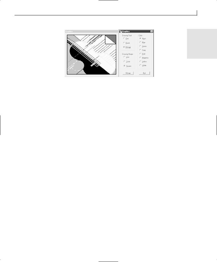
Adding Flash—Incorporating Graphics, Drawing, and Bitmaps |
177 |
8
Summary
What a way to start the week! You learned a lot today. You learned how Windows uses device context objects to allow you to draw graphics in the same way every time, without having to worry about what hardware users might have in their computers. You learned about some of the basic GDI objects, such as pens and brushes, and how they are used to draw figures on windows and dialogs. You also learned how you can load bitmaps from the system disk and display them onscreen for the user to see. You learned about the different pen and brush styles and how you can use these to draw the type of figure you want to draw. You also learned how you can specify colors for use with pens and brushes so that you can control how images appear to the user.
Q&A
QWhy do I need to specify both a pen and a brush if I just want to display one or the other?
AYou are always drawing with both when you draw any object that is filled in. The pen draws the outline, and the brush fills in the interior. You cannot choose to use one or the other; you have to use both. If you only want to display one or the other, you need to take special steps.
QWhy do all of the pen styles become solid when I increase the pen width above 1?
AWhen you increase the pen width, you are increasing the size of the dot that is used to draw with. If you remember Day 3, “Allowing User Interaction—Integrating the Mouse and Keyboard in Your Application,” when you first tried to draw by captur-

178 |
Day 8 |
ing each spot the mouse covered, all you drew were a bunch of dots. Well, when you increase the size of the dots that you are drawing the line with, the gaps between the dots are filled in from both sides, providing an unbroken line.
Workshop
The Workshop provides quiz questions to help you solidify your understanding of the material covered and exercises to provide you with experience in using what you’ve learned. The answers to the quiz questions and exercises are provided in Appendix B, “Answers.”
Quiz
1.What are the three values that are combined to specify a color?
2.What do you use to draw on windows without needing to know what graphics card the user has?
3.What size bitmap can you use to make a brush from it?
4.What event message is sent to a window to tell it to redraw itself?
5.How can you cause a window to repaint itself?
Exercises
1.Make the second dialog window resizable, and make it adjust the figures drawn on it whenever it’s resized.
2.Add a bitmap brush to the set of brushes used to create the rectangles and ellipses.

WEEK 2
DAY 9
Adding ActiveX Controls to Your Application
In today’s application develop market, there are thousands of prebuilt components that you can plug into your applications, extending the functionality of your applications instantaneously. Originally the domain of Visual Basic programmers, now you can use readily available ActiveX controls with just about any Windows programming language, including Visual C++. Today you will learn how you can add ActiveX controls to your Visual C++ applications, taking advantage of their existing functionality. Some of the topics that you will cover today are
•What ActiveX controls are and how they work.
•How you can add ActiveX controls to your project workspace.
•How you can use the ActiveX control in your Visual C++ application.
•How to call the various methods associated with the ActiveX control.
•How to handle events that are triggered by the ActiveX control.
180 |
Day 9 |
What Is an ActiveX Control?
An ActiveX control is a software component that can be plugged into many different programs and used as if it were a native part of the program. It’s similar to the concept of separate stereo components. If you buy a new tape deck, you can just plug it into the rest of your stereo and it works with everything else you already have. ActiveX controls bring this same type of interoperability to software applications.
ActiveX used to be called OLE 2.0. OLE 2.0 was Microsoft’s technology for combining two or more applications to make them work as one (or at least to switch between the various applications within the same application shell). This idea was an expansion from the original OLE (Object Linking and Embedding) technology, which only enabled you to combine documents created with different applications into a single document. When revamping OLE technologies to work in a distributed environment (such as on the Internet), Microsoft decided to also revamp the name. Thus, ActiveX was born.
ActiveX and the IDispatch Interface
The ActiveX technology is built on top of Microsoft’s COM (Component Object Model) technology, utilizing its interface and interaction model for making ActiveX control integration fairly seamless. The COM technology defines how ActiveX objects are constructed and how their interfaces are designed. The ActiveX technology defines a layer that is built on top of COM, what interfaces various objects should support, and how different types of objects should interact.
Note
Microsoft’s COM technology defines how applications and components can interact through the use of interfaces. An interface is like a function call into an ActiveX component. However, COM specifies how that function call must be built and called, and what supporting functionality must accompany the function call.
There are interfaces, like the IUnknown interface, that are required in every COM object, and which are used to query the component to find out what other interfaces are supported by the component. Each interface supports a specific set of functionality; you might have one interface to handle the visual appearance of the control, another to control how the control appearance interacts with the surrounding application, another that triggers events in the surrounding application, and so on.
Adding ActiveX Controls to Your Application |
181 |
One of the key technologies in ActiveX controls is automation. Automation enables an application embedded within another application to activate itself and control its part of the user interface or document, making its changes and then shutting itself down when the user moves on to another part of the application that isn’t controlled by the embedded application.
This process is what happens when you have an Excel spreadsheet embedded within a
Word document. If you click the spreadsheet, Excel becomes active and you can edit the 9 spreadsheet using Excel, even though you’re still working in Word. Then, once you finish
making your changes to the spreadsheet, Excel closes itself down and you can continue working in Word.
One of the keys to making automation work is a special interface called the IDispatch (also known as the dispinterface) interface. The IDispatch interface consists of a pointer to a table of available methods that can be run in the ActiveX control or embedded application. These methods have ID numbers, called DISPIDs, which are also loaded into a table that can be used to look up the ID for a specific method. Once you know the DISPID for a specific method, you can call that method by calling the Invoke method of the IDispatch interface, passing the DISPID to identify the method to be run. Figure 9.1 shows how the IDispatch interface uses the Invoke method to run methods in the ActiveX object.
FIGURE 9.1.
The IDispatch ActiveX interface.
182 |
Day 9 |
ActiveX Containers and Servers
To embed one ActiveX object within another ActiveX object, you have to implement the embedded object as an ActiveX server, and the object containing the first object must be an ActiveX container. Any ActiveX object that can be embedded within another is an ActiveX server, whether it is an entire application or just a small ActiveX control. Any ActiveX object that can have other ActiveX objects embedded within it is an ActiveX container.
Note
Don’t confuse the use of the terms container and server with the term client in the previous figure. The client is the object calling the other object’s IDispatch interface. As you’ll learn in a page or so, both the container and server call the other’s IDispatch interfaces, making each one the client of the other.
These two types of ActiveX objects are not mutually exclusive. An ActiveX server can also be an ActiveX container. A good example of this concept is Microsoft’s Internet Explorer Web browser. Internet Explorer is implemented as an ActiveX server that runs within an ActiveX container shell (that can also house Word, Excel, PowerPoint, or any other ActiveX server application). At the same time that Internet Explorer is an ActiveX server running within the browser shell, it can contain other ActiveX controls.
ActiveX controls are a special instance of an ActiveX server. Some ActiveX servers are also applications that can run on their own. ActiveX controls cannot run on their own and must be embedded within an ActiveX container. By using ActiveX components in your Visual C++ application, you automatically make your application an ActiveX container.
Most of the interaction between the ActiveX container and an ActiveX control takes place through three IDispatch interfaces. One of these IDispatch interfaces is on the control, and it is used by the container to make calls to the various methods that the ActiveX control makes available to the container.
The container provides two IDispatch interfaces to the control. The first of these IDispatch interfaces is used by the control to trigger events in the container application. The second interface is used to set properties of the control, as shown in Figure 9.2. Most properties of an ActiveX control are actually provided by the container but are maintained by the control. When you set a property for the control, the container calls a method in the control to tell the control to read the properties from the container. Most of this activity is transparent to you because Visual C++ builds a series of C++ classes around the ActiveX control’s interfaces. You will interact with the methods exposed by the C++ classes, not directly calling the control’s IDispatch interface.
|
Adding ActiveX Controls to Your Application |
183 |
||
FIGURE 9.2. |
|
IDispatch |
|
|
|
|
|
|
|
An ActiveX container |
|
(events) |
|
|
and control interact |
|
|
|
|
primarily through |
|
IDispatch |
|
|
a few IDispatch |
ActiveX |
ActiveX |
|
|
(properties) |
|
|||
interfaces. |
Container |
Control |
|
|
|
|
|||
IDispatch |
9 |
|
Adding an ActiveX Control to Your Project
Looking into how ActiveX controls work can be deceptive because of how easy it really is to use them in your applications. Visual C++ makes it easy to add ActiveX controls to your applications and even easier to use them. Before you begin adding the ActiveX control to your application, let’s create an application shell into which you will add an ActiveX control:
1.Create a new MFC AppWizard project named ActiveX.
2.Use the same defaults on the AppWizard as in previous days, but leave the check box for ActiveX Controls checked on the second AppWizard step. Give your application the title ActiveX Controls.
3.Once you generate an application shell, remove all the controls and add a single command button.
4.Set the button’s ID to IDC_EXIT and its caption to E&xit.
5.Using the Class Wizard, add a function to your command button on the BN_CLICKED event message.
6.Edit the function you just created, calling the OnOK function, as on earlier days.
Registering the Control
Before you add an ActiveX control to your dialog window, you need to register the control, both with Windows and with Visual C++. There are two possible ways to register the ActiveX control with Windows. The first way is to run any installation routine that came with the ActiveX control. If you do not have an installation routine, you need to register the control manually. To register the control manually, follow these steps:
1.Open a DOS shell.
2.Change directory to where the ActiveX control is on your system.
3.Run the regsvr32 command, specifying the name of the ActiveX control as the
184 |
Day 9 |
only command-line argument. For instance, if you were registering a control named MYCTL.OCX and it was located in your WINDOWS\SYSTEM directory, you would perform the following:
C:\WINDOWS> CD system
C:\WINDOWS\SYSTEM> regsvr32 MYCTL.OCX
Caution |
It is preferable to run any installation routine that comes with the control |
|
because registering the control manually might not enable the control for |
||
|
||
|
development usage. Controls can be licensed for development or deploy- |
|
|
ment. If a control is licensed for deployment, you will not be able to use it in |
|
|
your Visual C++ applications. This is a mechanism that protects control devel- |
|
|
opers by requiring that developers purchase a development license for con- |
|
|
trols; they can’t just use the controls they may have installed on their system |
|
|
with another application. |
|
|
|
Note
COM and ActiveX objects store a lot of information in the Windows Registry database. Whenever an application uses an ActiveX object, the operating system refers to the information in the Windows Registry to find the object and to determine whether the application can use the object in the way that it requested. Using the regsvr32.exe utility to register an ActiveX control places most of the required information about the control into the system Registry. However, there may be additional information about the control that needs to be in the Registry for the control to function properly.
Now that the ActiveX control that you want to use is registered with the operating system, you need to register it with Visual C++ and add it to your project. To do this, follow these steps:
1.Select Project | Add To Project | Components and Controls from the Visual C++ menu.
2.In the Components and Controls Gallery dialog, navigate to the Registered ActiveX Controls folder, as in Figure 9.3.
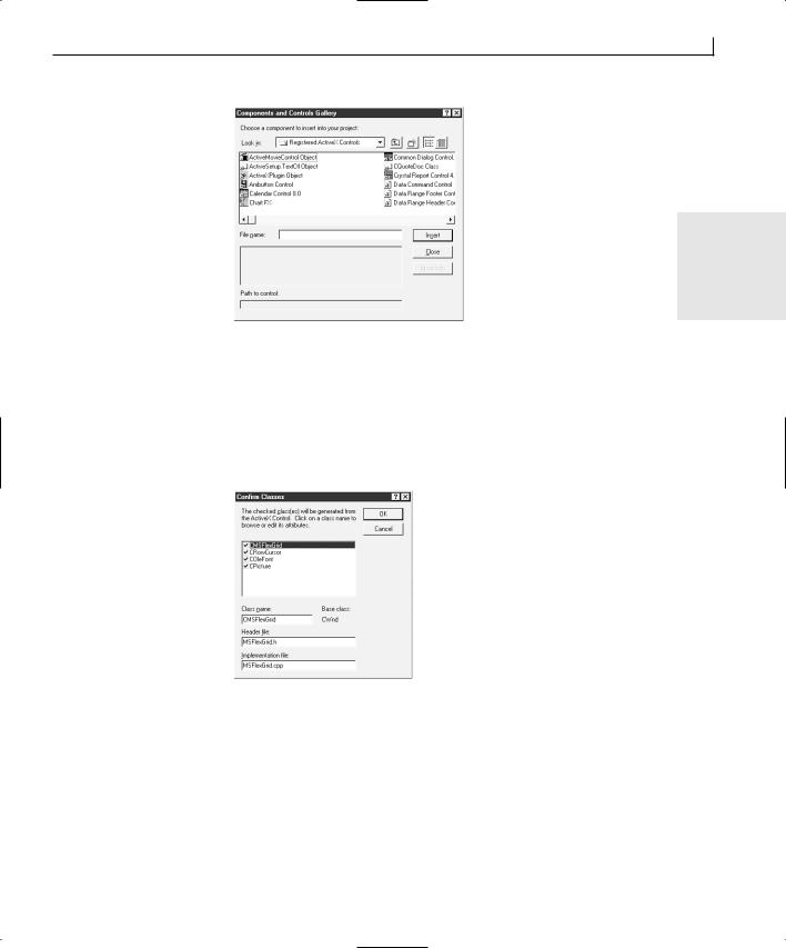
Adding ActiveX Controls to Your Application |
185 |
FIGURE 9.3.
The ActiveX controls that can be added to your project.
9
3.Select the control you want to register, such as the Microsoft FlexGrid control, and click the Insert button.
4.Click OK on the message box asking whether you want to insert this component in your project.
5.On the Confirm Classes dialog, click the OK button to add the C++ classes specified, as in Figure 9.4.
FIGURE 9.4.
Visual C++ tells you what classes will be added to your project.
6.Click the Close button on the Components and Controls Gallery dialog to finish adding controls to your project.
7.The FlexGrid control should have been added to the Control Palette for your dialog window, as in Figure 9.5.
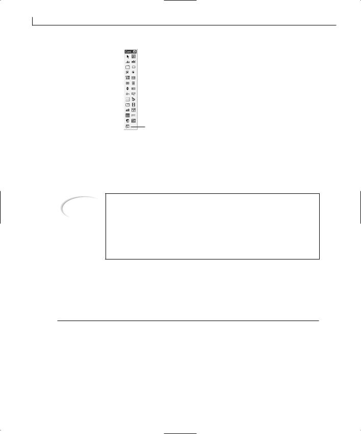
186 |
Day 9 |
FIGURE 9.5.
The ActiveX control
FlexGrid is added to the Control Palette for use on your dialog windows.
The FlexGrid control
If you examine the Class View area of the workspace pane, you see the four classes that Visual C++ added to your project. Expand the class trees and you see numerous methods for these classes. Visual C++ created these classes and methods by examining the ActiveX control that you just added and created class methods to call each of the methods in the control’s IDispatch interface.
Note
If you use older ActiveX controls in your Visual C++ applications, Visual C++ might not be able to generate the classes and methods to encapsulate the control’s functionality. The information in the control that provided Visual C++ with the information necessary to build these classes and methods is a more recent addition to the ActiveX specification. As a result, older controls might not provide this information, making them more difficult to use with Visual C++.
Adding the Control to Your Dialog
Now that you have added the FlexGrid control to your project, you can add it to your dialog window just as you would any other control. Set the control properties as in Table 9.1.
TABLE 9.1. CONTROL PROPERTY SETTINGS.
Object |
Property |
Setting |
FlexGrid control |
ID |
IDC_MSFGRID |
|
Rows |
20 |
|
Cols |
4 |
|
MergeCells |
2 - Restrict Rows |
|
Format |
< Region |< Product |
|
(FormatString) |
|< Employee |>Sales |
|
|
|
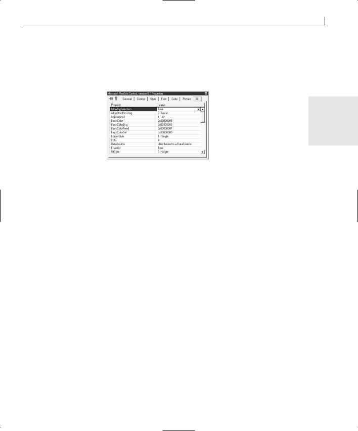
Adding ActiveX Controls to Your Application |
187 |
Once you add the control to your dialog window, you will notice that there is an additional tab on the properties dialog with all the control properties, as in Figure 9.6. You can choose to use this tab to set all the properties on the control, or you can go through the other tabs to set the properties, just as you would with the standard controls.
FIGURE 9.6.
ActiveX controls have |
9 |
a property tab that |
|
contains all control |
|
properties.
Once you have finished setting all the properties for the control, you’ll need to add a variable for the control so that you can interact with the control in your code. To add this variable, open the Member Variables tab on the Class Wizard and add a variable for the control. Because you are adding a variable for an ActiveX control, you can only add a control variable, so the only thing available for you to specify is the variable name. For this example application, name the variable m_ctlFGrid.
Using an ActiveX Control in Your Application
Once Visual C++ has generated all the classes to encapsulate the ActiveX control, working with the control is a simple matter of calling the various methods and responding to control events just like the standard controls. You’ll start with using the control methods to get information about the control and to modify data within the control. Then you’ll learn how to respond to control events with Visual C++.
Interacting with the Control
The application that you are building today will generate a number of product sales over five sales regions with four salespeople. You will be able to scroll through the data, which will be sorted by region and product, to compare how each salesperson did for each product.
To make this project, you will build an array of values that will be loaded into cells in the grid. The grid will then be sorted in ascending order, using the FlexGrid control’s internal sorting capabilities.

188 |
Day 9 |
Loading Data into the Control
The first thing you will do is create a function to load data into the FlexGrid control. Add a new function to the CActiveXDlg class by right-clicking the Class View of the workspace and choosing Add Member Function. Specify the Function Type as void, the Function Declaration as LoadData, and the access as Private. Click the OK button and edit the function, adding the code in Listing 9.1.
LISTING 9.1. THE LoadData FUNCTION.
1:void CActiveXDlg::LoadData()
2:{
3: |
int liCount; |
// The grid row count |
4: |
CString lsAmount; |
// The sales amount |
5: |
|
|
6:// Initialize the random number generator
7:srand((unsigned)time(NULL));
8:// Create Array in the control
9:for (liCount = m_ctlFGrid.GetFixedRows();
10:liCount < m_ctlFGrid.GetRows(); liCount++)
11:{
12:// Generate the first column (region) values
13:m_ctlFGrid.SetTextArray(GenID(liCount, 0), RandomStringValue(0));
14:// Generate the second column (product) values
15:m_ctlFGrid.SetTextArray(GenID(liCount, 1), RandomStringValue(1));
16:// Generate the third column (employee) values
17:m_ctlFGrid.SetTextArray(GenID(liCount, 2), RandomStringValue(2));
18:// Generate the sales amount values
19:lsAmount.Format(“%5d.00”, rand());
20:// Populate the fourth column
21:m_ctlFGrid.SetTextArray(GenID(liCount, 3), lsAmount);
22:}
23:
24:// Merge the common subsequent rows in these columns
25:m_ctlFGrid.SetMergeCol(0, TRUE);
26:m_ctlFGrid.SetMergeCol(1, TRUE);
27:m_ctlFGrid.SetMergeCol(2, TRUE);
28:
29:// Sort the grid
30:DoSort();
31:}
In this function, the first thing that you do is initialize the random number generator. Next, you loop through all of the rows in the control, placing data in each of the cells. You get the total number of rows in the control by calling the GetRows method and the number of the header row by calling the GetFixedRows method. You are able to add data
Adding ActiveX Controls to Your Application |
189 |
to the control cells by calling the SetTextArray method, which has the cell ID as the first argument and the cell contents as the second argument, both of which are generated by functions you’ll be creating in a few moments.
Once you have data in the grid cells, you call SetMergeCol, which tells the control that it |
|
can merge cells in the first three columns if adjacent rows contain the same value. |
|
Finally, you sort the control, using another function you have yet to create. |
|
Calculating the Cell ID |
9 |
The cells in the FlexGrid control are numbered sequentially from left to right, top to bottom. With your control, the first row, which contains the headers (and is already populated), has cells 0 through 3, the second row cells 4 through 7, and so on. Therefore, you can calculate the ID of a cell by adding its column number to the total number of columns in the control, multiplied by the current row number. For instance, if your control has four columns, and you are in the third column and fourth row, you can calculate your cell ID as 2 + (4 * 3) = 14. (Remember that the column and row numbers start with 0, so the third column is 2 and the fourth row is number 3.)
Now that you understand how you can calculate the cell ID, you need to implement that formula in a function. Add a new function to the CActiveXDlg class using the same method as for the LoadData function. The type of this function should be int and the description should be GenID(int m_iRow, int m_iCol). Once you add the function, edit it with the code in Listing 9.2.
LISTING 9.2. THE GenID FUNCTION.
1:int CActiveXDlg::GenID(int m_iRow, int m_iCol)
2:{
3:// Get the number of columns
4:int liCols = m_ctlFGrid.GetCols();
5:
6:// Generate an ID based on the number of columns,
7:// the current column, and the current row
8:return (m_iCol + liCols * m_iRow);
9:}
Generating Random Data
To populate the first three columns in the grid, you want to randomly generate data. In the first column, you want to put region names. In the second column, you want to put product names. And in the third column, you want to put salesperson names. By using a switch statement to determine which column you are generating data for and then using a

190 |
Day 9 |
modulus division on a randomly generated number in another switch statement, you can randomly select between a limited set of data strings.
To implement this functionality, add another function to the CActiveXDlg class with a type of CString and a description of RandomStringValue(int m_iColumn). Edit the resulting function, adding the code in Listing 9.3.
LISTING 9.3. THE RandomStringValue FUNCTION.
1:CString CActiveXDlg::RandomStringValue(int m_iColumn)
2:{
3: |
CString lsStr; |
// The return string |
4: |
int liCase; |
// A random value ID |
5: |
|
|
6:// Which column are we generating for?
7:switch (m_iColumn)
8:{
9:case 0: // The first column (region)
10:// Generate a random value between 0 and 4
11:liCase = (rand() % 5);
12:// What value was generated?
13:switch (liCase)
14:{
15:case 0:
16:// 0 - Northwest region
17:lsStr = “Northwest”;
18:break;
19:case 1:
20:// 1 - Southwest region
21:lsStr = “Southwest”;
22:break;
23:case 2:
24:// 2 - Midwest region
25:lsStr = “Midwest”;
26:break;
27:case 3:
28:// 3 - Northeast region
29:lsStr = “Northeast”;
30:break;
31:default:
32:// 4 - Southeast region
33:lsStr = “Southeast”;
34:break;
35:}
36:break;
37:case 1: // The second column (product)
38:// Generate a random value between 0 and 4
39:liCase = (rand() % 5);
40:// What value was generated?
41:switch (liCase)
Adding ActiveX Controls to Your Application
42:{
43:case 0:
44:// 0 - Dodads
45:lsStr = “Dodads”;
46:break;
47:case 1:
48:// 1 - Thingamajigs
49:lsStr = “Thingamajigs”;
50:break;
51:case 2:
52:// 2 - Whatchamacallits
53:lsStr = “Whatchamacallits”;
54:break;
55:case 3:
56:// 3 - Round Tuits
57:lsStr = “Round Tuits”;
58:break;
59:default:
60:// 4 - Widgets
61:lsStr = “Widgets”;
62:break;
63:}
64:break;
65:case 2: // The third column (employee)
66:// Generate a random value between 0 and 3
67:liCase = (rand() % 4);
68:// What value was generated?
69:switch (liCase)
70:{
71:case 0:
72:// 0 - Dore
73:lsStr = “Dore”;
74:break;
75:case 1:
76:// 1 - Harvey
77:lsStr = “Harvey”;
78:break;
79:case 2:
80:// 2 - Pogo
81:lsStr = “Pogo”;
82:break;
83:default:
84:// 3 - Nyra
85:lsStr = “Nyra”;
86:break;
87:}
88:break;
89:}
90:// Return the generated string
91:return lsStr;
92:}
191
9

192 |
Day 9 |
Sorting the Control
To sort the Grid control, you need to select all the columns and then set the sort to ascending. To implement this functionality, add one more function to the CActiveXDlg class with a type of void and a definition of DoSort. Edit the function as in Listing 9.4.
LISTING 9.4. THE DoSort FUNCTION.
1:void CActiveXDlg::DoSort()
2:{
3:// Set the current column to column 0
4:m_ctlFGrid.SetCol(0);
5:// Set the column selection to all columns
6:m_ctlFGrid.SetColSel((m_ctlFGrid.GetCols() - 1));
7:// Generic Ascending Sort
8:m_ctlFGrid.SetSort(1);
9:}
In the DoSort function, you set the current column to the first column using the SetCol method. Next you select from the current column to the last column using the SetColSel method, effectively selecting all columns in the control. Finally, you tell the control to sort the columns in ascending order by using the SetSort method, passing 1 as the flag for the sort order.
Now that you have all the functionality necessary to load the control with data, you need to call the LoadData function in the OnInitDialog function to load the data before the control is visible to the user. Edit the OnInitDialog function as in Listing 9.5 to load the data.
LISTING 9.5. THE OnInitDialog FUNCTION.
1:BOOL CActiveXDlg::OnInitDialog()
2:{
3:CDialog::OnInitDialog();
4:. 5:. 6:.
7: // TODO: Add extra initialization here 8:
9:///////////////////////
10:// MY CODE STARTS HERE
11:///////////////////////
13:// Load data into the Grid control
14:LoadData();
15:
16:///////////////////////
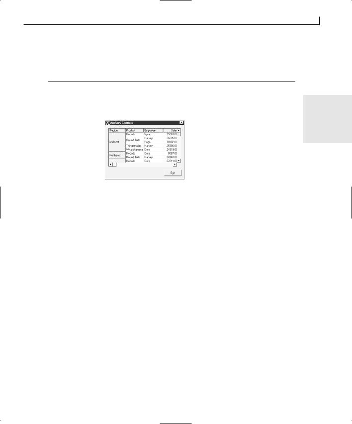
Adding ActiveX Controls to Your Application |
193 |
17:// MY CODE ENDS HERE
18:///////////////////////
20:return TRUE; // return TRUE unless you set the focus to a control
21:}
If you compile and run your application at this point, you find that it is loading the data |
|
and sorting it, as in Figure 9.7. |
9 |
|
FIGURE 9.7.
The FlexGrid populated with data.
Responding to Control Events
If you play with your application at this point, you know that the Grid control does not respond to any input that you might try to give it. If you click one of the cells and try to change the value, it doesn’t respond. What you need to do is add a control event to handle the input. ActiveX controls make several events available for use in Visual C++ applications. You can use the Class Wizard to browse through the available events and determine which events you need to give functionality and which to ignore. Most ActiveX controls don’t have any default functionality attached to the available events but instead expect you to tell the control what to do on each event.
You are going to add two control events to capture the mouse clicks and movements. You will add functionality to allow the user to click a column header and drag it to another position, thus rearranging the column order. To implement this functionality, you have to capture two control events, when the mouse button is pressed down and when it is released. On the first event, you need to check whether the user clicked a header, and if so, you capture the column selected. On the second event, you need to move the selected column to the column on which the mouse button was released.
To accomplish this functionality, you need to create a new class variable to maintain the clicked column number between the two events. Add a new variable to the CActiveXDlg class, just like you added the functions earlier, specifying the type as int, the variable name as m_iMouseCol, and the access as Private.
Capturing the Column Selected
194 |
Day 9 |
To capture the mouse click event for the control, follow these steps:
1. Using the Class Wizard, add a function for the MouseDown event message for the
IDC_MSFGRID object.
2. Edit the function using the code in Listing 9.6.
LISTING 9.6. THE OnMouseDownMsfgrid FUNCTION.
1: void CActiveXDlg::OnMouseDownMsfgrid(short Button, short Shift, long |
x, |
|
long y) |
|
|
2: { |
|
|
3: |
// TODO: Add your control notification handler code here |
|
4: |
|
|
5:///////////////////////
6:// MY CODE STARTS HERE
7:///////////////////////
9:// Did the user click on a data row and not the
10:// header row?
11:if (m_ctlFGrid.GetMouseRow() != 0)
12:{
13:// If so, then zero out the column variable
14:// and exit
15:m_iMouseCol = 0;
16:return;
17:}
18:// Save the column clicked on
19:m_iMouseCol = m_ctlFGrid.GetMouseCol();
21:///////////////////////
22:// MY CODE ENDS HERE
23:///////////////////////
24:}
In this function, you checked the row clicked by calling the GetMouseRow method. If the row is not the first row, then zero out the column-holding variable and exit the function. Otherwise, you need to get the column clicked by calling the GetMouseCol method. You can store the returned column number in the m_iMouseCol variable that you just added to the class.
Moving the Column Where Released
Now that you are capturing the selected column number, you need to capture the column on which the mouse is released. To capture the mouse release event for the control, follow these steps:
1. Using the Class Wizard, add a function for the MouseUp event message for the
Adding ActiveX Controls to Your Application |
195 |
IDC_MSFGRID object.
2. Edit the function using the code in Listing 9.7.
LISTING 9.7. THE OnMouseUpMsfgrid FUNCTION.
1: void CActiveXDlg::OnMouseUpMsfgrid(short Button, short Shift, long x, |
|
|
long y) |
9 |
|
2: { |
|
|
3: |
// TODO: Add your control notification handler code here |
|
4: |
|
|
5:///////////////////////
6:// MY CODE STARTS HERE
7:///////////////////////
9:// If the selected column was the first column,
10:// there’s nothing to do
11:if (m_iMouseCol == 0)
12:return;
13:// Turn the control redraw off
14:m_ctlFGrid.SetRedraw(FALSE);
15:// Change the selected column position
16:m_ctlFGrid.SetColPosition(m_iMouseCol, m_ctlFGrid.GetMouseCol());
17:// Resort the grid
18:DoSort();
19:// Turn redraw back on
20:m_ctlFGrid.SetRedraw(TRUE);
21:
22:///////////////////////
23:// MY CODE ENDS HERE
24:///////////////////////
25:}
In this function, you first check to see if there is a selected column to be moved. If not, you exit the function with nothing to do. If there is a column selected, you turn off the redraw on the control using the SetRedraw method so that none of the movement is seen by the user. Next, you move the selected column to the release column using the SetColPosition method. Once you move the column, you resort the grid by calling the DoSort function. Finally, you turn the control’s redraw back on so that the control is refreshed to show the user the moved column. If you compile and link your application, you should now be able to grab column headers and move the columns about, as in Figure 9.8.
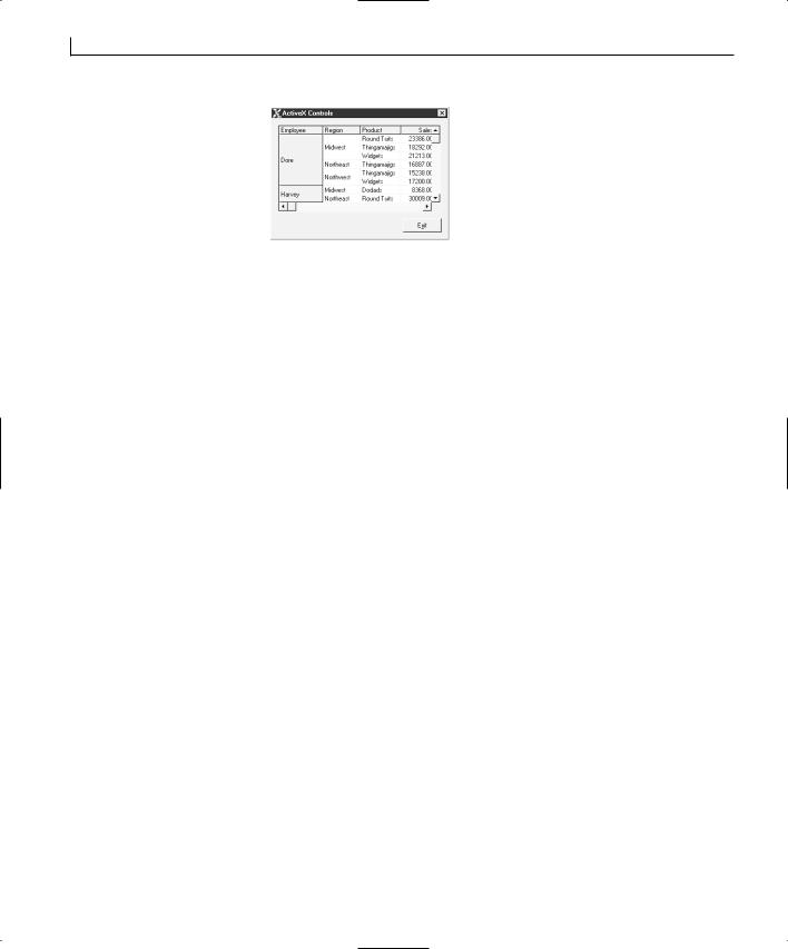
196 |
Day 9 |
FIGURE 9.8.
The FlexGrid with reordered columns.
Summary
Today you learned how you can use ActiveX controls in your Visual C++ applications to easily extend your application’s functionality. You learned the basics of how ActiveX controls work and how they interact with the containing application. You also learned how you can add an ActiveX control to your development project so that you can use it in your application. You saw how Visual C++ creates C++ classes to encapsulate the ActiveX controls that you add and how you can interact with the control through the exposed methods of these generated C++ classes. You also saw how you can capture events that are generated by the ActiveX control so that you can program your application to react to the events.
Q&A
QHow can I determine what methods are available to me when working with an ActiveX control?
ABy examining the C++ classes that Visual C++ builds to encapsulate the control, you can get a good idea of what functionality is available to you. If you have documentation for the control, you can compare it to the C++ class to determine which class method calls which control method. You can examine the events listed for the control in the Class Wizard to determine which events are also available.
QHow can I use the ActiveX controls that were installed on my machine with another application in my Visual C++ applications?
AIt depends on how the controls are licensed and what application installed the controls. If the controls were installed by another application development tool, chances are that you have a development license for the control, in which case you should be able to use them in your Visual C++ applications. If the controls were installed by an end-user application, such as Word or Quicken, then odds are that you have only a runtime license for the control. If you want to use these controls in your own applications, you need to contact the control developer to acquire a development license for the controls.

Adding ActiveX Controls to Your Application |
197 |
QBecause the FlexGrid control does not allow me to enter data directly into the control, how can I let my users enter data into the grid as if they were using a spreadsheet?
A To implement this functionality for the FlexGrid control, you need to add a floating |
|
Edit Box control to your window. Your code needs to determine which cell the user |
|
wants to edit and float the edit box in front of that cell. This arrangement allows |
|
|
|
the user to feel as if he is entering data directly into the cell. Another approach is to |
9 |
have a data-entry field outside the grid, much like is used in Excel, into which the |
|
user enters the data. You can highlight the cells as the user maneuvers around the |
|
Grid control to give the user visceral feedback for her actions. |
|
|
|
Workshop
The Workshop provides quiz questions to help you solidify your understanding of the material covered and exercises to provide you with experience in using what you’ve learned. The answers to the quiz questions and exercises are provided in Appendix B, “Answers.”
Quiz
1.How does an ActiveX container call methods in an ActiveX control?
2.How does an ActiveX control trigger events in the container application?
3.What AppWizard option must be selected for ActiveX controls to work properly in a Visual C++ application?
4.How does Visual C++ make it easy to work with ActiveX controls?
5.Why might it be difficult to work with older controls in Visual C++?
Exercise
Modify the application so that the user can double-click a column header and make it the first column in the grid.


WEEK 2
DAY 10
Creating Single Document
Interface Applications
Today you will learn a different way of approaching application development with Visual C++ than you have used with the previous days’ lessons. Today you will learn how to create Single Document Interface (SDI) applications. An SDI application is a document-centric application that can only work with one document at a time, and can only work with one type of document.
Some good examples of SDI applications are Notepad, WordPad, and Paint. All of these applications can do only one type of task and can only work on one task at a time. WordPad is almost like an SDI version of Word. It’s able to perform a large number of the tasks that Word does, but although Word allows you to work on numerous documents at the same time, WordPad limits you to only one document.
Some of the things that you will learn today are
• The Document/View architecture that Visual C++ uses for creating SDI applications.

200 |
Day 10 |
•How to create an SDI application shell.
•How to separate your data from the visual representation of the data.
•How to encapsulate your data in its own C++ class.
•How to create interaction between the data and the menus.
The Document/View Architecture
When you create an SDI application, more classes are created for an SDI application than for a dialog-style application. Each of these classes serves a specific purpose in how SDI applications operate. Ignoring the About window dialog class, four specific classes make up an SDI application:
•The CWinApp-derived class
•The CFrameView-derived class
•The CDocument-derived class
•The CView-derived class
The CWinApp class creates all the other components in the application. It is the class that receives all the event messages and then passes the messages to the CFrameView and CView classes.
The CFrameView class is the window frame. It holds the menu, toolbar, scrollbars, and any other visible objects attached to the frame. This class determines how much of the document is visible at any time. Very little (if any) of your programming efforts on SDI applications will require making any modifications or additions to either of these first two classes.
The CDocument class houses your document. This class is where you will build the data structures necessary to house and manipulate the data that makes up your document. This class receives input from the CView class and passes display information to the CView class. This class is also responsible for saving and retrieving the document data from files.
The CView class is the class that displays the visual representation of your document for the user. This class passes input information to the CDocument class and receives display information from the CDocument class. Most of the coding that you will do for this class consists of drawing the document for the user and handling the input from the user. The CView class has several descendent classes that can be used as the ancestor for the view class. These descendent classes are listed in Table 10.1.
Creating Single Document Interface Applications |
201 |
TABLE 10.1. THE CView DESCENDENT CLASSES. |
|
||
|
Class |
Description |
|
|
|
|
|
|
CEditView |
Provides the functionality of a edit box control. Can be used to |
|
|
|
implement simple text-editor functionality. |
|
|
CFormView |
The base class for views containing controls. Can be used to provide |
|
|
|
form-based documents in applications. |
|
|
CHtmlView |
Provides the functionality of a Web browser. This view directly han- |
|
|
|
dles the URL navigation, hyperlinking, and so on. Maintains a history |
|
|
|
list for browsing forward and back. |
|
|
CListView |
Provides list-control functionality in the Document/View architecture. |
|
|
CRichEditView |
Provides character and paragraph formatting functionality. Can be |
|
|
|
used to implement a word-processor application. |
10 |
|
CScrollView |
Provides scrolling capabilities to a CView class. |
|
|
CTreeView |
Provides tree-control functionality in the Document/View architecture. |
|
|
|
|
|
All four of these classes work together to make up the full functionality of an SDI application, as shown in Figure 10.1. By taking advantage of this architecture, you can build powerful document-centric applications with relative ease.
FIGURE 10.1.
The Document/View architecture.
Application object
(CWinApp)
Document object
Messages passed to the frame window and view object
(CFrameView) |
Frame window |
View object |
(CView) |
(CDocument)
Two-way flow of information between the document and the view objects
202 |
Day 10 |
Note
Don’t let the term document mislead you. This doesn’t mean that you can only create applications such as word processors and spreadsheets. In this situation, the term document refers to the data that is processed by your application, whereas view refers to the visual representation of that data. For instance, the Solitaire application could be implemented as a Document/View application, with the document being the cards and their position in the playing area. In this case, the view is the display of the cards, drawing each card where the document specifies it should be.
Creating an SDI Application
To get a good idea of how the Document/View architecture works, and of how you can use it to build applications, you will build a new version of the drawing application you created on Day 3, “Allowing User Interaction—Integrating the Mouse and Keyboard in Your Application.” In this version, the user’s drawing will be persistent, which means it is not erased each time another window is placed in front of the application. This version will also be able to save and restore drawings.
Building the Application Shell
To create the application shell for today’s application, follow these steps:
1.Create a new AppWizard project. Name the project Day10.
2.On the first step of the AppWizard, select Single Document.
3.Use the default values on the second step of the AppWizard.
4.On the third step of the AppWizard, uncheck the support for ActiveX Controls.
5.On the fourth step of the AppWizard, leave all the default values. Click the Advanced button.
6.In the Advanced Options dialog, enter a three-letter file extension for the files that your application will generate (for example, dhc or dvp). Click the Close button to close the dialog and then click Next to move to the next step of the AppWizard.
7.Use the default settings on the fifth step of the AppWizard.
8.On the sixth and final AppWizard step, you can choose the base class on which your view class will be based. Leave the base class as CView and click Finish. The AppWizard will generate the application shell.
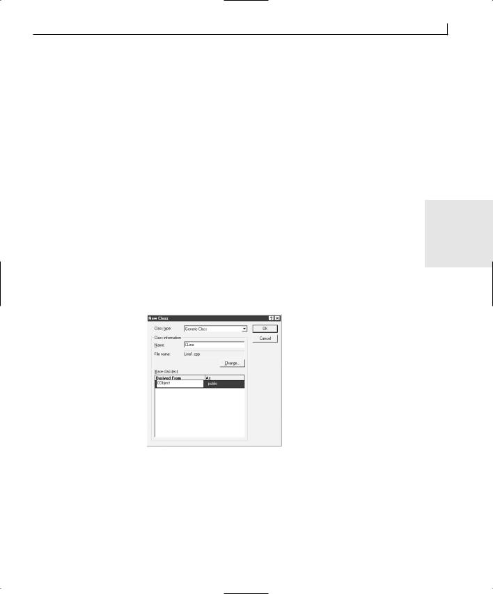
Creating Single Document Interface Applications |
203 |
Creating a Line Class
One of the first issues that you will need to tackle is how to represent your data in the document class. For the drawing application, you have a series of lines. Each line consists of a starting point and ending point. You might think that you can use a series of points for the data representation. If you do this, you also have to make special accommodations for where one series of lines between points ends and the next begins. It makes much more sense to represent the drawing as a series of lines. This allows you to store each individual line that is drawn on the window without having to worry where one set of contiguous lines ends and where the next begins.
Unfortunately, the Microsoft Foundation Classes (MFC) does not have a line object |
|
class, although it does have a point object class (CPoint). I guess you’ll just have to create |
|
your own line class by following these steps: |
10 |
|
1.In the Class View tab of the workspace pane, select the top-level object in the tree (Day10 classes). Right-click the mouse and select New Class from the pop-up menu.
2.In the New Class dialog, select Generic Class for the class type. Enter CLine for the class name and click in the first line in the Base Class list box. Enter CObject as the base class, leaving the class access as public, as in Figure 10.2.
FIGURE 10.2.
The New Class Wizard.
3.When you click the OK button to add the CLine class, you may be told that the Class Wizard cannot find the appropriate header file for inheriting the CLine class from the CObject class, as in Figure 10.3. Click on the OK button on this message box.
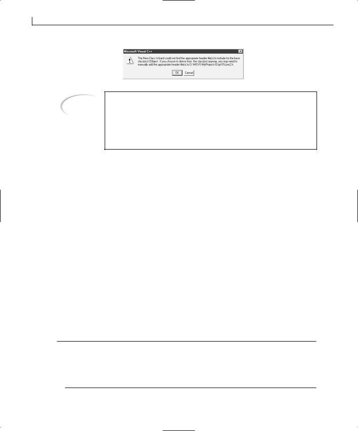
204 |
Day 10 |
FIGURE 10.3.
Warning about including the base class definition.
Note
The appropriate header class is already included in the CLine class files. Until your compiler complains because it can’t find the definition for the CObject class, don’t worry about this message. However, if you are using a base class that’s a bit further down the MFC class hierarchy, you might need to heed this message and add the appropriate header file to the include statements in the class source code file.
Constructing the CLine Class
At this time, your CLine class needs to hold only two data elements, the two end points of the line that it represents. You want to add those two data elements and add a class constructor that sets both values when creating the class instance. To do this, follow these steps:
1.In the Class View tab of the workspace pane, select the CLine class.
2.Right-click the CLine class and choose Add Member Variable from the pop-up menu.
3.Enter CPoint as the variable type and m_ptFrom as the variable name, and mark the access as Private. Click OK to add the variable.
4.Repeat steps 2 and 3, naming this variable m_ptTo.
5.Right-click the CLine class and choose Add Member Function from the pop-up menu.
6.Leave the function type blank, and enter CLine(CPoint ptFrom, CPoint ptTo) for the function declaration. Click OK to add the function.
7.Edit the new function, adding the code in Listing 10.1.
LISTING 10.1. THE CLine CONSTRUCTOR.
1:CLine::CLine(CPoint ptFrom, CPoint ptTo)
2:{
3://Initialize the from and to points
4:m_ptFrom = ptFrom;
5:m_ptTo = ptTo;
6:}
Creating Single Document Interface Applications |
205 |
In this object constructor, you are initializing the from and to points with the points that were passed in to the constructor.
Drawing the CLine Class
To follow correct object-oriented design, your CLine class should be able to draw itself so that when the view class needs to render the line for the user, it can just pass a message to the line object, telling it to draw itself. To add this functionality, follow these steps:
1.Add a new function to the CLine class by selecting Add Member Function from the pop-up menu.
2.Specify the function type as void and the function declaration as Draw(CDC *pDC).
3.Add the code in Listing 10.2 to the Draw function you just added.
LISTING 10.2. THE CLine Draw FUNCTION. |
10 |
|
1:void CLine::Draw(CDC * pDC)
2:{
3:// Draw the line
4:pDC->MoveTo(m_ptFrom);
5:pDC->LineTo(m_ptTo);
6:}
This function is taken almost directly from the application you built a week ago. It’s a simple function that moves to the first point on the device context and then draws a line to the second point on the device context.
Implementing the Document Functionality
Now that you have an object to use for representing the drawings made by the user, you can store these CLine objects on the document object in a simple dynamic array. To hold this array, you can add a CObArray member variable to the document class.
The CObArray class is an object array class that dynamically sizes itself to accommodate the number of items placed in it. It can hold any objects that are descended from the CObject class, and it is limited in size only by the amount of memory in the system. Other dynamic array classes in MFC include CStringArray, CByteArray, CWordArray, CDWordArray, and CPtrArray. These classes differ by the type of objects they can hold.
Add the CObArray to CDay10Doc, using the Add Member Variable Wizard and giving it a
name of m_oaLines.
Adding Lines
206 |
Day 10 |
The first functionality that you need to add to the document class is the ability to add new lines. This should be a simple process of getting the from and to points, creating a new line object, and then adding it to the object array. To implement this function, add a new member function to the CDay10Doc class, specifying the type as CLine* and the declaration as AddLine(CPoint ptFrom, CPoint ptTo) with public access. Edit the function, adding the code in Listing 10.3.
LISTING 10.3. THE CDay10Doc AddLine FUNCTION.
1:CLine * CDay10Doc::AddLine(CPoint ptFrom, CPoint ptTo)
2:{
3:// Create a new CLine object
4:CLine *pLine = new CLine(ptFrom, ptTo);
5:try
6:{
7:// Add the new line to the object array
8:m_oaLines.Add(pLine);
9:// Mark the document as dirty
10:SetModifiedFlag();
11:}
12:// Did we run into a memory exception?
13:catch (CMemoryException* perr)
14:{
15:// Display a message for the user, giving him or her the
16:// bad news
17:AfxMessageBox(“Out of memory”, MB_ICONSTOP | MB_OK);
18:// Did we create a line object?
19:if (pLine)
20:{
21:// Delete it
22:delete pLine;
23:pLine = NULL;
24:}
25:// Delete the exception object
26:perr->Delete();
27:}
28:return pLine;
29:}
At first, this function is understandable. You create a new CLine instance, passing the from and to points as constructor arguments. Right after that, however, you have something interesting, the following flow control construct:
1:try
2:{

Creating Single Document Interface Applications |
207 |
6:}
7:catch (...)
8:{
10:.
11:.
12:}
What is this? This construct is an example of structured exception handling. Some code could fail because of a factor beyond your control, such as running out of memory or disk space, you can place a try section around the code that might have a problem. The try section should always be followed by one or more catch sections. If a problem occurs during the code in the try section, the program immediately jumps to the catch sections. Each catch section specifies what type of exception it handles (in the case of the AddLine
function, it specifically handles memory exceptions only), and if there is a matching 10 catch section for the type of problem that did occur, that section of code is executed to
give the application a chance to recover from the problem. If there is no catch section for the type of problem that did occur, your program jumps to a default exception handler, which will most likely shut down your application. For more information on structured exception handling, see Appendix A, “C++ Review.”
Within the try section, you add the new CLine instance to the array of line objects. Next, you call the SetModifiedFlag function, which marks the document as “dirty” (unsaved) so that if you close the application or open another file without saving the current drawing first, the application prompts you to save the current drawing (with the familiar Yes, No, Cancel message box).
In the catch section, you inform the user that the system is out of memory and then clean up by deleting the CLine object and the exception object.
Finally, at the end of the function, you return the CLine object to the calling routine. This enables the view object to let the line object draw itself.
Getting the Line Count
The next item you will add to the document class is a function to return the number of lines in the document. This functionality is necessary because the view object needs to loop through the array of lines, asking each line object to draw itself. The view object will need to be able to determine the total number of lines in the document and retrieve any specific line from the document.
Returning the number of lines in the document is a simple matter of returning the number of lines in the object array, so you can just return the return value from the GetSize method of the CObArray class. To implement this function, add a new member function to
208 |
Day 10 |
the CDay10Doc class, specifying the type as int and the declaration as GetLineCount with public access. Edit the function, adding the code in Listing 10.4.
LISTING 10.4. THE CDay10Doc GetLineCount FUNCTION.
1:int CDay10Doc::GetLineCount()
2:{
3:// Return the array count
4:return m_oaLines.GetSize();
5:}
Retrieving a Specific Line
Finally, you need to add a function to return a specific line from the document. This is a simple matter of returning the object at the specified position in the object array. To implement this function, add a new member function to the CDay10Doc class, specifying the type as CLine* and the declaration as GetLine(int nIndex) with public access. Edit the function, adding the code in Listing 10.5.
LISTING 10.5. THE CDay10Doc GetLine FUNCTION.
1:CLine * CDay10Doc::GetLine(int nIndex)
2:{
3:// Return a pointer to the line object
4:// at the specified point in the object array
5:return (CLine*)m_oaLines[nIndex];
6:}
Note
Notice that the object being returned had to be cast as a pointer to a CLine object. Because the CObArray class is an array of CObjects, every element that is returned by the array is a CObject instance, not a CLine object instance.
Showing the User
Now that you have built the capability into the document class to hold the drawing, you need to add the functionality to the view object to read the user’s drawing input and to draw the image. The mouse events to capture the user input are almost identical to those you created a week ago. The second part of the functionality that you need to implement

Creating Single Document Interface Applications |
209 |
is drawing the image. You will make an addition to a function that already exists in the view object class.
Before adding these functions, you need to add a member variable to the CDay10View class to maintain the previous mouse point, just as you did a week ago. Add a member variable to the CDay10View class through the workspace pane, specifying the type as CPoint, the name as m_ptPrevPos, and the access as private.
Adding the Mouse Events
To add the mouse events to capture the user’s drawing efforts, open the Class Wizard and add functions to the CDay10View class for the WM_LBUTTONDOWN, WM_LBUTTONUP, and
WM_MOUSEMOVE event messages. Edit the functions as in Listing 10.6.
LISTING 10.6. THE CDay10View MOUSE FUNCTIONS. |
10 |
1:void CDay10View::OnLButtonDown(UINT nFlags, CPoint point)
2:{
3:// TODO: Add your message handler code here and/or call default
5:///////////////////////
6:// MY CODE STARTS HERE
7:///////////////////////
9:// Capture the mouse, so no other application can
10:// grab it if the mouse leaves the window area
11:SetCapture();
12:// Save the point
13:m_ptPrevPos = point;
14:
15:///////////////////////
16:// MY CODE ENDS HERE
17:///////////////////////
19:CView::OnLButtonDown(nFlags, point);
20:}
21:
22:void CDay10View::OnLButtonUp(UINT nFlags, CPoint point)
23:{
24:// TODO: Add your message handler code here and/or call default
26:///////////////////////
27:// MY CODE STARTS HERE
28:///////////////////////
30:// Have we captured the mouse?
continues

210 |
Day 10 |
LISTING 10.6. CONTINUED
31:if (GetCapture() == this)
32:// If so, release it so other applications can
33:// have it
34:ReleaseCapture();
35:
36:///////////////////////
37:// MY CODE ENDS HERE
38:///////////////////////
40:CView::OnLButtonUp(nFlags, point);
41:}
42:
43:void CDay10View::OnMouseMove(UINT nFlags, CPoint point)
44:{
45:// TODO: Add your message handler code here and/or call default
47:///////////////////////
48:// MY CODE STARTS HERE
49:///////////////////////
51:// Check to see if the left mouse button is down
52:if ((nFlags & MK_LBUTTON) == MK_LBUTTON)
53:{
54:// Have we captured the mouse?
55:if (GetCapture() == this)
56:{
57:// Get the Device Context
58:CClientDC dc(this);
59:
60:// Add the line to the document
61:CLine *pLine = GetDocument()->AddLine(m_ptPrevPos, point);
63:// Draw the current stretch of line
64:pLine->Draw(&dc);
65:
66:// Save the current point as the previous point
67:m_ptPrevPos = point;
68:}
69:}
70:
71:///////////////////////
72:// MY CODE ENDS HERE
73:///////////////////////
75:CView::OnMouseMove(nFlags, point);
76:}
Creating Single Document Interface Applications |
211 |
In the OnLButtonDown function, the first thing you do is call the SetCapture function. This function “captures” the mouse, preventing any other applications from receiving any mouse events, even if the mouse leaves the window space of this application. This enables the user to drag the mouse outside the application window while drawing and then drag the mouse back into the application window, without stopping the drawing. All mouse messages are delivered to this application until the mouse is released in the OnLButtonUp function, using the ReleaseCapture function. In the meantime, by placing the GetCapture function in an if statement and comparing its return value to this, you can determine whether your application has captured the mouse. If you capture the mouse, you want to execute the rest of the code in those functions; otherwise, you don’t.
In the OnMouseMove function, after you create your device context, you do several things in a single line of code. The line
10
CLine *pLine = GetDocument()->AddLine(m_ptPrevPos, point);
creates a new pointer to a CLine class instance. Next, it calls the GetDocument function, which returns a pointer to the document object. This pointer is used to call the document class’s AddLine function, passing the previous and current points as arguments. The return value from the AddLine function is used to initialize the CLine object pointer. The CLine pointer can now be used to call the line object’s Draw function.
Note
A pointer is the address of an object. It is used to pass an object more efficiently around a program. Passing a pointer to an object, instead of the object itself, is like telling someone that the remote control is “on the couch between the second and third cushion, beside the loose pocket change” instead of handing the remote to the person. Actually, in programming terms, handing the remote to the person requires making an exact copy of the remote and handing the copy to the other person. It is obviously more efficient to tell the person where to find the remote than to manufacture an exact copy of the remote.
The notation -> denotes that the object’s functions or properties are accessed through a pointer, as opposed to directly through the object itself with the period (.) notation.
Drawing the Painting
In the view class, the function OnDraw is called whenever the image presented to the user needs to be redrawn. Maybe another window was in front of the application window, the window was just restored from being minimized, or a new document was just loaded from a file. Why the view needs to be redrawn doesn’t matter. All you need to worry

212 |
Day 10 |
about as the application developer is adding the code to the OnDraw function to render the document that your application is designed to create.
Locate the OnDraw function in the CDay10View class and add the code in Listing 10.7.
LISTING 10.7. THE CDay10View OnDraw FUNCTION.
1:void CDay10View::OnDraw(CDC* pDC)
2:{
3:CDay10Doc* pDoc = GetDocument();
4:ASSERT_VALID(pDoc);
5:
6: // TODO: add draw code for native data here 7:
8:///////////////////////
9:// MY CODE STARTS HERE
10: ///////////////////////
11:
12:// Get the number of lines in the document
13:int liCount = pDoc->GetLineCount();
14:
15:// Are there any lines in the document?
16:if (liCount)
17:{
18:int liPos;
19:CLine *lptLine;
20:
21:// Loop through the lines in the document
22:for (liPos = 0; liPos < liCount; liPos++)
23:{
24:// Get the from and to point for each line
25:lptLine = pDoc->GetLine(liPos);
26:// Draw the line
27:lptLine->Draw(pDC);
28:}
29:}
30:
31:///////////////////////
32:// MY CODE ENDS HERE
33:///////////////////////
34:}
In this function, the first thing you did was find out how many lines are in the document to be drawn. If there aren’t any lines, then there is nothing to do. If there are lines in the document, you loop through the lines using a for loop, getting each line object from
the document and then calling the line object’s Draw function.
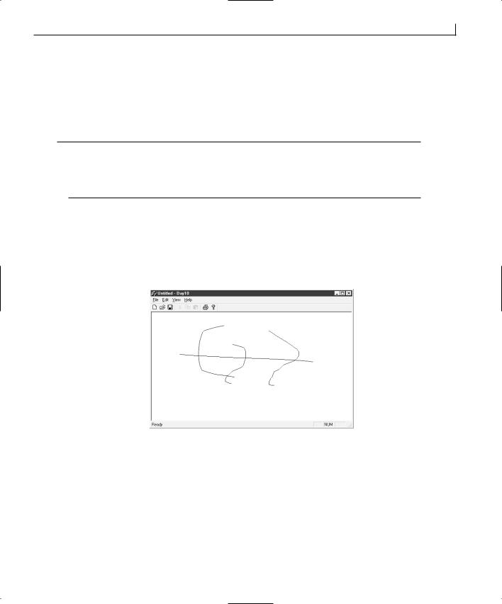
Creating Single Document Interface Applications |
213 |
Before you can compile and run your application, you’ll need to include the header file for the Cline class in the source code file for the document and view classes. To add this to your application, edit both of these files (Day10Doc.cpp and Day10View.cpp), adding the Line.h file to the includes, as shown in Listing 10.8.
LISTING 10.8. THE CDay10Doc includes.
1: #include “stdafx.h” 2: #include “Day10.h” 3: #include “MainFrm.h” 4: #include “Line.h”
5: #include “Day10Doc.h”
At this point, you should be able to compile and run your application, drawing figures in |
10 |
|
it as shown in Figure 10.4. If you minimize the window and then restore it, or if you |
||
|
||
place another application window in front of your application window, your drawing |
|
|
should still be there when your application window is visible again (unlike the applica- |
|
|
tion you built a week ago). |
|
|
|
FIGURE 10.4.
Drawing with your application.
Saving and Loading the Drawing
Now that you can create drawings that don’t disappear the moment you look away, it’d be nice if you could make them even more persistent. If you play with the menus on your application, it appears that the Open, Save, and Save As menu entries on the File menu activate, but they don’t seem to do anything. The printing menu entries all work, but the entries for saving and loading a drawing don’t. Not even the New menu entry works! Well, you can do something to fix this situation.
214 |
Day 10 |
Deleting the Current Drawing
If you examine the CDay10Doc class, you’ll see the OnNewDocument function that you can edit to clear out the current drawing. Wrong! This function is intended for initializing any class settings for starting work on a new drawing and not for clearing out an existing drawing. Instead, you need to open the Class Wizard and add a function on the DeleteContents event message. This event message is intended for clearing the current contents of the document class. Edit this new function, adding the code in Listing 10.9.
LISTING 10.9. THE CDay10Doc DeleteContents FUNCTION.
1:void CDay10Doc::DeleteContents()
2:{
3:// TODO: Add your specialized code here and/or call the base class
5:///////////////////////
6:// MY CODE STARTS HERE
7:///////////////////////
9:// Get the number of lines in the object array
10:int liCount = m_oaLines.GetSize();
11:int liPos;
12:
13:// Are there any objects in the array?
14:if (liCount)
15:{
16:// Loop through the array, deleting each object
17:for (liPos = 0; liPos < liCount; liPos++)
18:delete m_oaLines[liPos];
19:// Reset the array
20:m_oaLines.RemoveAll();
21:}
22:
23:///////////////////////
24:// MY CODE ENDS HERE
25:///////////////////////
27:CDocument::DeleteContents();
28:}
This function loops through the object array, deleting each line object in the array. Once all the lines are deleted, the array is reset by calling its RemoveAll method. If you compile and run your application, you’ll find that you can select File | New, and if you decide not to save your current drawing, your window is wiped clean.
Creating Single Document Interface Applications |
215 |
Saving and Restoring the Drawing
Adding the functionality to save and restore your drawings is pretty easy to implement, but it might not be so easy to understand. That’s okay; you’ll spend an entire day on understanding saving and restoring files, also known as serialization, in three days. In the meantime, find the Serialize function in the CDay10Doc class. The function should look something like
1:void CDay10Doc::Serialize(CArchive& ar)
2:{
3:if (ar.IsStoring())
4:{
5:// TODO: add storing code here
6:}
7:else
8: |
{ |
10 |
9: |
// TODO: add loading code here |
|
10: |
} |
|
11: } |
|
|
Remove all the contents of this function, and edit the function so that it looks like Listing 10.10.
LISTING 10.10. THE CDay10Doc Serialize FUNCTION.
1:void CDay10Doc::Serialize(CArchive& ar)
2:{
3:///////////////////////
4:// MY CODE STARTS HERE
5:///////////////////////
6:
7:// Pass the serialization on to the object array
8:m_oaLines.Serialize(ar);
9:
10:///////////////////////
11:// MY CODE ENDS HERE
12:///////////////////////
13:}
This function takes advantage of the functionality of the CObArray class. This object array will pass down its array of objects, calling the Serialize function on each of the objects. This means that you need to add a Serialize function to the CLine class. Specify it as a void function type with the declaration of Serialize(CArchive& ar). Edit the function, adding the code in Listing 10.11.
216 |
Day 10 |
LISTING 10.11. THE CLine Serialize FUNCTION.
1:void CLine::Serialize(CArchive &ar)
2:{
3:CObject::Serialize(ar);
4:
5:if (ar.IsStoring())
6:ar << m_ptFrom << m_ptTo;
7:else
8:ar >> m_ptFrom >> m_ptTo;
9:}
This function follows basically the same flow that the original Serialize function would have followed in the CDay10Doc class. It uses the I/O stream functionality of C++ to save and restore its contents.
At this point, if you compile and run your application, you expect the save and open functions to work. Unfortunately, they don’t (yet). If you run your application and try to save a drawing, a message box will tell you that the application was unable to save the file, as in Figure 10.5.
FIGURE 10.5.
Unable to save drawings.
The reason that you are unable to save your drawing is that Visual C++ must be told that a class should be serializable. To do this, you add one line to the CLine class header file and one line to the CLine source code file. Open the CLine header file (Line.h), and add the
line in Listing 10.12 just after the first line of the class definition.
LISTING 10.12. THE Line.h EDIT FOR SERIALIZATION.
1:class CLine : public CObject
2:{
3:DECLARE_SERIAL (CLine)
4:public:
5:CLine(CPoint ptFrom, CPoint ptTo, UINT nWidth, COLORREF crColor);
Next, open the CLine source code file, and add the IMPLEMENT_SERIAL line in Listing 10.13 just before the class constructor functions.
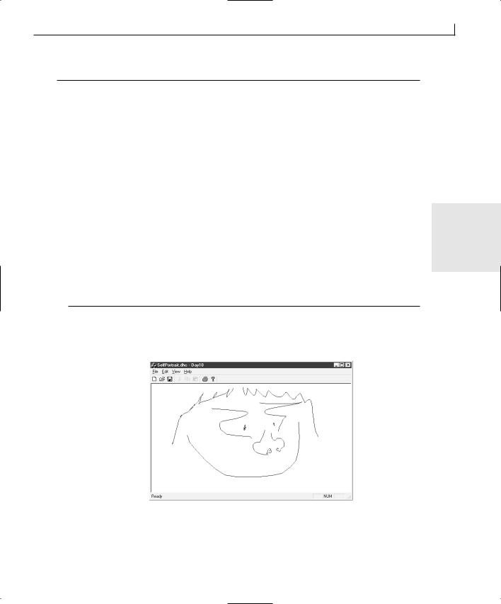
Creating Single Document Interface Applications |
217 |
LISTING 10.13. THE Line.cpp EDIT FOR SERIALIZATION.
1:// Line.cpp: implementation of the CLine class.
2://
3://////////////////////////////////////////////////////////////////////
5:#include “stdafx.h”
6:#include “Day10.h”
7:#include “Line.h”
9:#ifdef _DEBUG
10: #undef THIS_FILE |
|
11: static char THIS_FILE[]=__FILE__; |
|
12: #define new DEBUG_NEW |
|
13: #endif |
|
14: |
10 |
15: IMPLEMENT_SERIAL (CLine, CObject, 1) |
16://////////////////////////////////////////////////////////////////////
17:// Construction/Destruction
18://////////////////////////////////////////////////////////////////////
20:CLine::CLine()
21:{
23:}
Now if you compile and run your application, you should be able to draw your own selfportrait and save it for posterity, as shown in Figure 10.6.
FIGURE 10.6.
My self-portrait.

218 |
Day 10 |
Interacting with the Menu
Now that you have a working drawing program, it would be nice if the user could choose the color with which she wants to draw. Adding this functionality requires making changes in the CLine class to associate the color with the line and to CDay10Doc to maintain the currently selected color. Finally, you need to add a pull-down menu to select the desired color.
Adding Color to the CLine Class
The changes to the CLine class are fairly straightforward. The first thing that you need to do is to add another member variable to the CLine class to hold the color of each line. Next, you need to modify the class constructor to add color to the list of attributes to be passed in. Third, you need to modify the Draw function to use the specified color. Finally, you need to modify the Serialize function to save and restore the color information along with the point information. To do all these things, follow these steps:
1.Select the CLine class in the Class View tab of the workspace pane. Right-click the mouse and select Add Member Variable from the pop-up menu.
2.Specify the variable type as COLORREF, the name as m_crColor, and the access as private. Click OK to add the variable.
3.Right-click the CLine constructor in the Class View tree. Select Go to Declaration from the pop-up menu.
4.Add COLORREF crColor as a third argument to the constructor declaration.
5.Right-click the CLine constructor in the Class View tree. Select Go to Definition from the pop-up menu.
6.Modify the constructor to add the third argument and to set the m_crColor member to the new argument, as in Listing 10.14.
LISTING 10.14. THE MODIFIED CLine CONSTRUCTOR.
1:CLine::CLine(CPoint ptFrom, CPoint ptTo, COLORREF crColor)
2:{
3://Initialize the from and to points
4:m_ptFrom = ptFrom;
5:m_ptTo = ptTo;
6:m_crColor = crColor;
7:}
7. Scroll down to the Draw function and modify it as in Listing 10.15.
Creating Single Document Interface Applications |
219 |
LISTING 10.15. THE MODIFIED Draw FUNCTION.
1:void CLine::Draw(CDC * pDC)
2:{
3:// Create a pen
4:CPen lpen (PS_SOLID, 1, m_crColor);
6:// Set the new pen as the drawing object
7:CPen* pOldPen = pDC->SelectObject(&lpen);
8:// Draw the line
9:pDC->MoveTo(m_ptFrom);
10:pDC->LineTo(m_ptTo);
11:// Reset the previous pen
12:pDC->SelectObject(pOldPen);
13:}
10
8. Scroll down to the Serialize function and modify it as in Listing 10.16.
LISTING 10.16. THE MODIFIED Serialize FUNCTION.
1:void CLine::Serialize(CArchive &ar)
2:{
3:CObject::Serialize(ar);
4:
5:if (ar.IsStoring())
6:ar << m_ptFrom << m_ptTo << (DWORD) m_crColor;
7:else
8:ar >> m_ptFrom >> m_ptTo >> (DWORD) m_crColor;
9:}
The only part of any of these steps that should be a surprise is that you are capturing the return value from the SelectObject function when you are specifying the pen to use in drawing the lines. You didn’t do this last week. The return value from the SelectObject function is the pen that was in use before you changed it. This way, you can use the previous pen to restore it to the device context when you are done drawing.
Adding Color to the Document
The changes that you need to make to the CDay10Doc class are just slightly more extensive than those made to the CLine class. You need to add a member variable to hold the current color and a color table to convert color IDs into RGB values. You need to initialize the current color variable in the OnNewDocument function. Then, you need to modify the AddLine function to add the current color to the CLine constructor. Finally, you add a function to return the current color. That’s all that you need to do for now until you start

220 |
Day 10 |
adding menu message handlers for setting the current color. To do these things, follow these steps:
1.Select the CDay10Doc class in the Class View tab on the workspace pane. Rightclick the mouse and choose Add Member Variable from the pop-up menu.
2.Specify the variable type as UINT, the name as m_nColor, and the access as private. Click OK to add the variable.
3.Repeat step 1.
4.Specify the variable type as “ static const COLORREF,” the name as m_crColors[8], and the access as public.
5.Open the CDay10Doc source code (Day10Doc.cpp) and add the population of the m_crColors color table as in Listing 10.17.
LISTING 10.17. THE COLOR TABLE SPECIFICATION.
1://}}AFX_MSG_MAP
2:END_MESSAGE_MAP()
4:const COLORREF CDay10Doc::m_crColors[8] = {
5: |
RGB( |
0, |
0, |
0), // Black |
|
6: |
RGB( |
0, |
0, 255), |
// Blue |
|
7: |
RGB( |
0, 255, |
0), |
// Green |
|
8: |
RGB( |
0, 255, 255), |
// Cyan |
||
9: |
RGB( 255, |
0, |
0), |
// Red |
|
10: |
RGB( 255, |
0, 255), |
// Magenta |
||
11: |
RGB( 255, 255, |
0), |
// Yellow |
||
12: |
RGB( 255, 255, 255) |
// White |
|||
13: }; |
|
|
|
|
|
14: |
|
|
|
|
|
15://////////////////////////////////////////////////////////////////////
16:// CDay10Doc construction/destruction
17:
18:CDay10Doc::CDay10Doc()
19:.
20:.
21:.
22:}
6.Scroll down to the OnNewDocument function and edit it as in Listing 10.18.
Creating Single Document Interface Applications |
221 |
LISTING 10.18. THE MODIFIED OnNewDocument FUNCTION.
1:BOOL CDay10Doc::OnNewDocument()
2:{
3:if (!CDocument::OnNewDocument())
4:return FALSE;
5:
6:// TODO: add reinitialization code here
7:// (SDI documents will reuse this document)
9:///////////////////////
10:// MY CODE STARTS HERE
11:///////////////////////
13: |
// Initialize the color to black |
14: |
m_nColor = ID_COLOR_BLACK - ID_COLOR_BLACK; |
15: |
10 |
16:///////////////////////
17:// MY CODE ENDS HERE
18:///////////////////////
20:return TRUE;
21:}
7.Scroll down to the AddLine function, and modify it as in Listing 10.19.
LISTING 10.19. THE MODIFIED AddLine FUNCTION.
1:CLine * CDay10Doc::AddLine(CPoint ptFrom, CPoint ptTo)
2:{
3:// Create a new CLine object
4:CLine *pLine = new CLine(ptFrom, ptTo, m_crColors[m_nColor]);
5:try
6:{
7:// Add the new line to the object array
8:m_oaLines.Add(pLine);
9:// Mark the document as dirty
10:SetModifiedFlag();
11:}
12:// Did we run into a memory exception?
13:catch (CMemoryException* perr)
14:{
15:// Display a message for the user, giving him or her the
16:// bad news
17:AfxMessageBox(“Out of memory”, MB_ICONSTOP | MB_OK);
18:// Did we create a line object?
19:if (pLine)
continues
222 |
Day 10 |
LISTING 10.19. CONTINUED
20:{
21:// Delete it
22:delete pLine;
23:pLine = NULL;
24:}
25:// Delete the exception object
26:perr->Delete();
27:}
28:return pLine;
29:}
8.Add a new member function to the CDay10Doc class. Specify the function type as UINT, the declaration as GetColor, and the access as public.
9.Edit the GetColor function, adding the code in Listing 10.20.
LISTING 10.20. THE GetColor FUNCTION.
1:UINT CDay10Doc::GetColor()
2:{
3:// Return the current color
4:return ID_COLOR_BLACK + m_nColor;
5:}
In the OnNewDocument and the GetColor functions, the color is added and subtracted from ID_COLOR_BLACK. This is the lowest numbered color menu ID when you add the menu entries. These calculations maintain the variable as a number between 0 and 7, but when working with the menus, they allow comparison with the actual menu IDs.
Modifying the Menu
Now comes the fun part. You need to add a new pull-down menu to the main menu. You need to add menu entries for all the colors in the color table. You need to add message handlers for all the color menu entries. Finally, you need to add event handlers to check the menu entry that is the current color. To do all of this, follow these steps:
1.Select the Resource View tab in the workspace pane. Expand the tree so that you can see the contents of the Menu folder. Double-click the menu resource.
2.Grab the blank top-level menu (at the right end of the menu bar) and drag it to the left, dropping it in front of the View menu entry.
3.Open the properties for the blank menu entry. Specify the caption as &Color. Close the properties dialog.
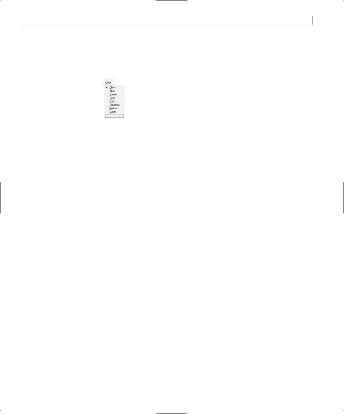
Creating Single Document Interface Applications |
223 |
4.Add submenu entries below the Color top-level menu. Specify the submenus in order, setting their properties as specified in Table 10.2. You should wind up with a menu looking like Figure 10.7.
FIGURE 10.7.
The Color menu as designed.
TABLE 10.2. MENU PROPERTY SETTINGS. |
|
|
|
|||
|
Object |
Property |
Setting |
|
||
10 |
||||||
|
|
|
|
|
||
|
Menu Entry |
ID |
ID_COLOR_BLACK |
|||
|
|
|||||
|
|
Caption |
&Black |
|
||
|
Menu Entry |
ID |
ID_COLOR_BLUE |
|
||
|
|
Caption |
B&lue |
|
||
|
Menu Entry |
ID |
ID_COLOR_GREEN |
|
||
|
|
Caption |
&Green |
|
||
|
Menu Entry |
ID |
ID_COLOR_CYAN |
|
||
|
|
Caption |
&Cyan |
|
||
|
Menu Entry |
ID |
ID_COLOR_RED |
|
||
|
|
Caption |
&Red |
|
||
|
Menu Entry |
ID |
ID_COLOR_MAGENTA |
|
||
|
|
Caption |
&Magenta |
|
||
|
Menu Entry |
ID |
ID_COLOR_YELLOW |
|
||
|
|
Caption |
&Yellow |
|
||
|
Menu Entry |
ID |
ID_COLOR_WHITE |
|
||
|
|
Caption |
&White |
|
||
|
|
|
|
|
|
|
5.Open the Class Wizard. Select the CDay10Doc in the Class Name combo box.
6.Add functions for both the C O M M A N D and UPDATE_COMMAND_UI event messages for all the color menu entries.
7.After the final menu entry function has been added, click Edit Code.
8.Edit the Black menu functions as in Listing 10.21.

224 |
Day 10 |
LISTING 10.21. THE BLACK MENU FUNCTIONS.
1:void CDay10Doc::OnColorBlack()
2:{
3:// TODO: Add your command handler code here
5:///////////////////////
6:// MY CODE STARTS HERE
7:///////////////////////
9:// Set the current color to black
10: m_nColor = ID_COLOR_BLACK - ID_COLOR_BLACK; 11:
12:///////////////////////
13:// MY CODE ENDS HERE
14:///////////////////////
15:}
16:
17:void CDay10Doc::OnUpdateColorBlack(CCmdUI* pCmdUI)
18:{
19:// TODO: Add your command update UI handler code here
21:///////////////////////
22:// MY CODE STARTS HERE
23:///////////////////////
25:// Determine if the Black menu entry should be checked
26:pCmdUI->SetCheck(GetColor() == ID_COLOR_BLACK ? 1 : 0);
28:///////////////////////
29:// MY CODE ENDS HERE
30:///////////////////////
31:}
9.Edit the Blue menu functions as in Listing 10.22. Edit the remaining menu functions in the same way, substituting their menu IDs for ID_COLOR_BLUE.
LISTING 10.22. THE BLUE MENU FUNCTIONS.
1:void CDay10Doc::OnColorBlue()
2:{
3:// TODO: Add your command handler code here
5:///////////////////////
6:// MY CODE STARTS HERE
7:///////////////////////
9:// Set the current color to blue

Creating Single Document Interface Applications |
225 |
10: m_nColor = ID_COLOR_BLUE - ID_COLOR_BLACK; 11:
12:///////////////////////
13:// MY CODE ENDS HERE
14:///////////////////////
15:}
16:
17:void CDay10Doc::OnUpdateColorBlue(CCmdUI* pCmdUI)
18:{
19:// TODO: Add your command update UI handler code here
21:///////////////////////
22:// MY CODE STARTS HERE
23:///////////////////////
25:// Determine if the Blue menu entry should be checked
26: |
pCmdUI->SetCheck(GetColor() == ID_COLOR_BLUE ? 1 : 0); |
10 |
|
||
27: |
|
|
28:///////////////////////
29:// MY CODE ENDS HERE
30:///////////////////////
31:}
In the first of the two menu functions, the C OMMAN D function, the current color variable is set to the new color. If you add the menu entries in the correct order, their ID numbers are sequential, starting with ID_COLOR_BLACK. Subtracting ID_COLOR_BLACK from the menu ID should always result in the correct position in the color table for the selected color. For example, the Black color is position 0 in the color table. ID_COLOR_BLACK − ID_COLOR_BLACK = 0. Blue is position 1 in the color table. Because ID_COLOR_BLUE should be one greater than ID_COLOR_BLACK, ID_COLOR_BLUE — ID_COLOR_BLACK = 1.
The second function, the UPDATE_COMMAND_UI function, may need a little explaining. The UPDATE_COMMAND_UI event is called for each menu entry just before it is displayed. You can use this event message function to check or uncheck the menu entry, based on whether it is the current color. You can also use this event to enable or disable menu entries or make other modifications as necessary. The code in this function
pCmdUI->SetCheck(GetColor() == ID_COLOR_BLUE ? 1 : 0);
does several things. First, the pCmdUI object that is passed in as the only argument is a pointer to a menu object. The SetCheck function can check or uncheck the menu entry, depending on whether the argument passed is 1 or 0 (1 checks, 0 unchecks). The argument portion for the SetCheck function is a flow-control construct that can be somewhat
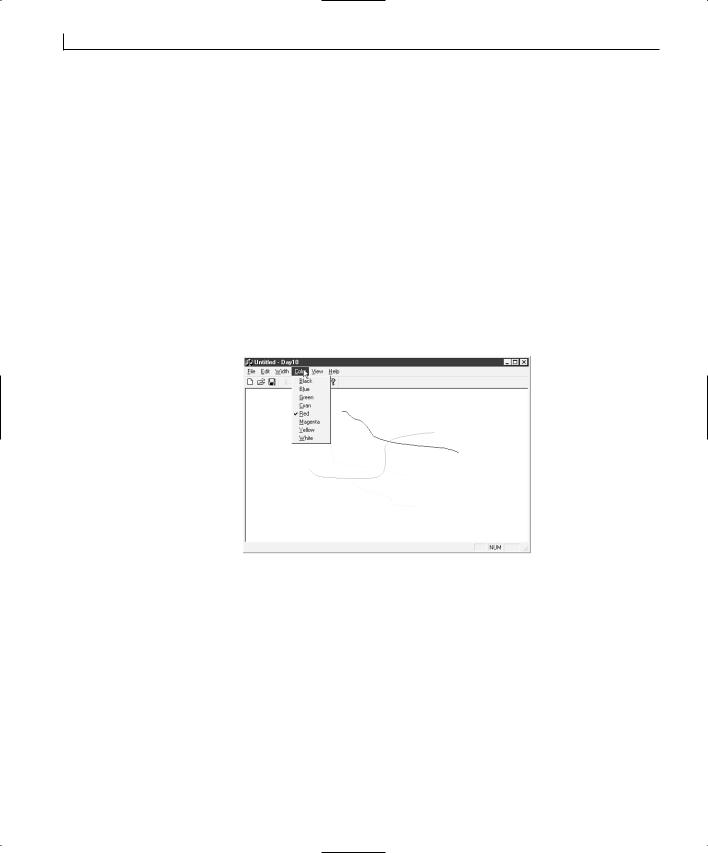
226 |
Day 10 |
confusing if you haven’t spent a large amount of time programming in C/C++. The first half
GetColor() == ID_COLOR_BLUE
is a simple boolean conditional statement. It results in a true or false result. The portion following this conditional statement
? 1 : 0
is basically an if...else statement in shorthand. If the conditional statement is true, then the value is 1, and if the statement is false, the value is 0. This is a fancy way of placing an if..else flow control within the argument to another function.
If you compile and run your application, you should be able to change the color that you are drawing with. When you pull down the color menu, you should see the current drawing color checked on the menu, as in Figure 10.8.
FIGURE 10.8.
Specifying the current color on the menu.
Summary
Whew! What a day! You learned quite a bit today because this was a packed chapter. You initially learned about the SDI style application and about a couple of standard applications that you have probably used that are SDI applications. You next learned about the Document/View architecture that Visual C++ uses for SDI applications. You learned to create a simple class of your own for use in your drawing application. You created a drawing application that can maintain the images drawn using it. You learned how you can save and restore documents in the Document/View architecture. You also learned about the CObArray object array class and how you can use it to create a dynamic object array for storing various classes. Finally, you learned how you can check and uncheck menu entries in MFC applications.

Creating Single Document Interface Applications |
227 |
Q&A
QIs there any way that you can reduce the number of C O M M A N D and UPDATE_ COMMAND_UI functions for the menus?
AYes, you can send all the color C O M M A N D events to the same function. From there, you can examine the nID value (which is passed as an argument) and compare it to the menu IDs to determine which menu is calling the function. As a result, you can write the C O M M A N D function for the color menus as follows:
void CDay10Doc::OnColorCommand(UINT nID)
{
// TODO: Add your command handler code here |
|
/////////////////////// |
|
// MY CODE STARTS HERE |
10 |
/////////////////////// |
// Set the current color to blue m_nColor = nID - ID_COLOR_BLACK;
///////////////////////
// MY CODE ENDS HERE
///////////////////////
}
For the UPDATE_COMMAND_UI functions, you can do the same thing, only slightly differently. In this case, you can examine the pCmdUI->m_nID value to determine which menu the function is being called for. This makes the UPDATE_COMMAND_UI function look like the following:
void CDay10Doc::OnUpdateColor(CCmdUI* pCmdUI)
{
// TODO: Add your command update UI handler code here
///////////////////////
//MY CODE STARTS HERE
///////////////////////
//Determine if the Blue menu entry should be checked pCmdUI->SetCheck(GetColor() == pCmdUI->m_nID ? 1 : 0);
///////////////////////
// MY CODE ENDS HERE
///////////////////////
}

228 |
Day 10 |
Q What’s the difference between SDI and MDI applications?
AAlthough SDI applications can perform only one task, MDI (Multiple Document Interface) applications can have multiple documents open at the same time. Plus, in an MDI application, not all document types need be the same. You’ll learn more about MDI applications tomorrow.
Workshop
The Workshop provides quiz questions to help you solidify your understanding of the material covered and exercises to provide you with experience in using what you’ve learned. The answers to the quiz questions and exercises are provided in Appendix B, “Answers.”
Quiz
1.What does SDI stand for?
2.What functionality is in the view class?
3.What function is called to redraw the document if the window has been hidden behind another window?
4.Where do you place code to clear out the current document before starting a new document?
5.What is the purpose of the document class?
Exercise
Add another pull-down menu to control the width of the pen used for drawing. Give it the following settings:
Menu Entry |
Width Setting |
Very Thin |
1 |
Thin |
8 |
Medium |
16 |
Thick |
24 |
Very Thick |
32 |
Tip
In the pen constructor, the second argument is the width.

WEEK 2
DAY 11
Creating Multiple
Document Interface
Applications
Today, you will learn how to build Multiple Document Interface (MDI) applications using Visual C++. You will be able to build applications that allow users to work on multiple documents at one time, switching between the windows of the application to do their work. In this chapter, you will learn
•The difference between SDI and MDI applications.
•How to create an MDI application.
•How to send multiple menu entries to a single event-handling function.
•How to add a context menu to a Document/View style application.
What Is an MDI Application?
As far as coding an MDI application with Visual C++, there’s little difference between creating an SDI and an MDI application. However, when you get
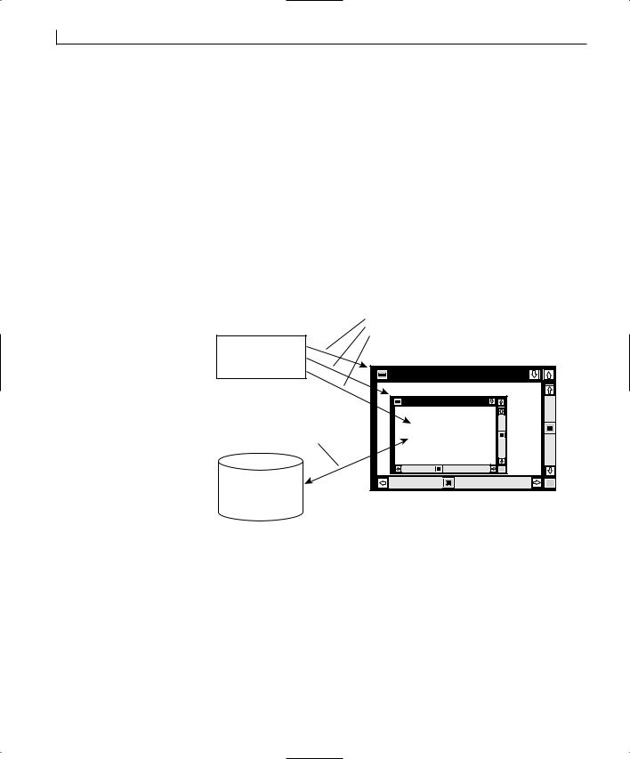
230 |
Day 11 |
deeper into the two application styles, you’ll find quite a few differences. Although an SDI application allows the user to work on only one document at a time, it also normally limits the user to working on a specific type of document. MDI applications not only enable the user to work on multiple documents at the same time, but also MDI applications can allow the user to work on multiple types of documents.
An MDI application uses a window-in-a-window style, where there is a frame window around one or more child windows. This is a common application style with many popular software packages, including Word and Excel.
Architecturally, an MDI application is similar to an SDI application. In fact, with a simple MDI application, the only difference is the addition of a second frame class to the other classes that the AppWizard creates, as shown in Figure 11.1. As you can see, the Document/View architecture is still very much the approach you use for developing MDI applications as well as SDI applications.
FIGURE 11.1. |
|
Messages passed to the |
The MDI Document/ |
|
frame window and view |
|
object |
|
View architecture. |
|
|
Application object |
|
|
|
|
|
|
(CWinApp) |
|
|
|
Main Frame window |
|
|
(CMainFrame) |
|
Two-way flow of |
Child Frame window |
|
(CChildView) |
|
|
information between |
|
|
|
|
|
the document and the |
View object |
|
view objects |
|
|
(CView) |
|
|
|
|
|
Document object |
|
|
(CDocument) |
|
When you create an MDI application, you will create just one more class than you created with an SDI application. The classes are
•The CWinApp derived class
•The CMDIFrameWnd derived class
•The CMDIChildWnd derived class
•The CDocument derived class
•The CView derived class
Creating Multiple Document Interface Applications |
231 |
The two MDI derived classes, CMDIFrameWnd (the CMainFrame class in your project) and CMDIChildWnd (the CChildFrame class in your project), are the only two classes that are different from the SDI application that you created.
The first of these two classes, the CMDIFrameWnd-derived CMainFrame, is the main frame of the application. It provides an enclosed space on the desktop within which all application interaction takes place. This frame window is the frame to which the menu and toolbars are attached.
The second of these two classes, the CMDIChildWnd-derived CChildFrame class, is the frame that holds the CView class. It is the frame that passes messages and events to the view class for processing or display.
In a sense, the functionality of the frame class in the SDI application has been split into these two classes in an MDI application. There is additional support for running multiple child frames with their own document/view class instances at the same time.
Creating an MDI Drawing Program
To get a good understanding of just how alike the Document/View architectures are for |
11 |
||
the SDI and MDI applications, today you will implement that same drawing application |
|||
|
|||
that you created yesterday, only this time as an MDI application. |
|
||
Building the Application Shell |
|
||
To create the application shell for today’s application, follow these steps: |
|
||
1. |
Create a new AppWizard project. Name the project Day11. |
|
|
2. |
On the first step of the AppWizard, select Multiple Documents, as shown in |
|
|
|
Figure 11.2. |
|
|
FIGURE 11.2.
Specifying an MDI application.

232 |
Day 11 |
3.Use the default values on the second step of the AppWizard.
4.On the third step of the AppWizard, uncheck the support for ActiveX Controls.
5.On the fourth step of the AppWizard, leave all the default values. Click the Advanced button.
6.In the Advanced Options dialog, enter a three-letter file extension for the files that your application will generate (for example, dhc or dvp). Click the Close button to close the dialog and then click Next to move to the next step of the AppWizard.
7.Use the default settings on the fifth step of the AppWizard.
8.On the sixth and final AppWizard step, leave the base class as CView and click Finish. The AppWizard generates the application shell.
Building the Drawing Functionality
Because you are creating the same application that you created yesterday, only as an MDI application this time, you need to add the same functionality to the application that you added yesterday. To save time, and to reemphasize how alike these two application architectures are, perform the same steps you did yesterday to create the CLine class and add the functionality to the CDay11Doc and CDay11View classes. Add the support into the CDay11Doc and CLine classes for selecting colors and widths, but do not add any menu event message handlers or create the color menu. When you finish adding all that functionality, you should have an application in which you can open multiple drawings, all drawing with only the color black.
Caution |
Because you haven’t created the menus yet, and the color initialization uses |
|
the color menu IDs, you will probably have to hard-code the initialization of |
||
|
||
|
the color to 0 to get your application to compile. Once you add the color |
|
|
menu, the menu IDs should have been added, so you will be able to return |
|
|
to using the IDs in your code. For the time being, change the line of code in |
|
|
the OnNewDocument function in the CDay11Doc class from |
|
|
m_nColor = ID_COLOR_BLACK - ID_COLOR_BLACK; |
|
|
to |
|
|
m_nColor = 0; |
|
|
You will also need to make the same sort of change to the GetColor function |
|
|
because it uses one of the color menu IDs also. |
|
|
|
Creating Multiple Document Interface Applications |
233 |
Adding Menu Handling Functionality
Now that you’ve got all the functionality in your application, you would probably like to add the color menu so you can use all those available colors in your drawings. When you expand the Resource View tree and look in the Menu folder, you’ll find not one, but two menus defined. Which one do you add the color menu to?
The IDR_MAINFRAME menu is the menu that is available when no child windows are open. If you run your application and close all child windows, you’ll see the menu change, removing all the menus that apply to child windows. Once you open another document, either by creating a new document or by opening an existing document, the menu changes back, returning all the menus that apply to the documents.
The IDR_DAY11TYPE menu is the menu that appears when a child window is open. This menu contains all the functions that apply to documents. Therefore, this is the menu that you need to add the color menu to. Add the color menu by following the same directions as yesterday, using the same menu properties.
Once you add all the menus, you need to add the menu event handlers. Today, you are going to take a different approach to implementing the menu event handlers than you did
yesterday. The Q&A section at the end of yesterday’s chapter had a discussion of using a 11 single event-handler function for all the color menus. That is what you are going to
implement today. Unfortunately, the Class Wizard doesn’t understand how to route multiple menu event messages to the same function correctly, so you’re going to implement this yourself by following these steps:
1.Open the Day11Doc.h header file.
2.Scroll down toward the bottom of the header file until you find the protected section where the AFX_MSG message map is declared (search for
//{{AFX_MSG(CDay11Doc)).
3.Add the function declarations in Listing 11.1 before the line that you searched for. (The string that you searched for is the beginning marker for the Class Wizard maintained message map. Anything you place between it and the end marker, //}}AFX_MSG, is likely to be removed or corrupted by the Class Wizard.)
LISTING 11.1. THE EVENT-HANDLER DECLARATIONS IN Day11Doc.h.
.
.
.
1:#ifdef _DEBUG
2:virtual void AssertValid() const;
continues

234 |
Day 11 |
LISTING 11.1. CONTINUED
3:virtual void Dump(CDumpContext& dc) const;
4:#endif
5:
6: protected: 7:
8:// Generated message map functions
9:protected:
10:afx_msg void OnColorCommand(UINT nID);
11:afx_msg void OnUpdateColorUI(CCmdUI* pCmdUI);
12://{{AFX_MSG(CDay11Doc)
13:// NOTE - the ClassWizard will add and remove member functions here.
14:// DO NOT EDIT what you see in these blocks of generated code !
15://}}AFX_MSG
16:DECLARE_MESSAGE_MAP()
17:private:
18:UINT m_nColor;
19:CObArray m_oaLines;
20:};
4.Open the Day11Doc.cpp source-code file.
5.Search for the line BEGIN_MESSAGE_MAP and add the lines in Listing 11.2 just after it. It’s important that this code be between the BEGIN_MESSAGE_MAP line and the //{{AFX_MSG_MAP line. If these commands are between the //{{AFX_MSG_MAP and //}}AFX_MSG_MAP lines, then the Class Wizard will remove or corrupt them.
LISTING 11.2. THE EVENT-HANDLER MESSAGE MAP ENTRIES IN Day11Doc.cpp.
1://////////////////////////////////////////////////////////////////////
2:// CDay11Doc
3:
4: IMPLEMENT_DYNCREATE(CDay11Doc, CDocument) 5:
6:BEGIN_MESSAGE_MAP(CDay11Doc, CDocument)
7:ON_COMMAND_RANGE(ID_COLOR_BLACK, ID_COLOR_WHITE, OnColorCommand)
8:ON_UPDATE_COMMAND_UI_RANGE(ID_COLOR_BLACK, ID_COLOR_WHITE,
OnUpdateColorUI)
9://{{AFX_MSG_MAP(CDay11Doc)
10:// NOTE - the ClassWizard will add and remove mapping macros here.
11:// DO NOT EDIT what you see in these blocks of generated code!
12://}}AFX_MSG_MAP
13:END_MESSAGE_MAP()
Creating Multiple Document Interface Applications |
235 |
14:
15: const COLORREF CDay11Doc::m_crColors[8] = {
16: |
RGB( |
0, |
0, 0), |
// Black |
17: |
RGB( |
0, |
0, 255), |
// Blue |
18:.
19:.
20:.
6.Scroll to the bottom of the file and add the two event message handler functions in Listing 11.3.
LISTING 11.3. THE COLOR MENU EVENT-HANDLER FUNCTIONS.
1:void CDay11Doc::OnColorCommand(UINT nID)
2:{
3:// Set the current color
4:m_nColor = nID - ID_COLOR_BLACK;
5:}
6:
7:void CDay11Doc::OnUpdateColorUI(CCmdUI* pCmdUI)
8:{
9: |
// Determine if the menu entry should be checked |
11 |
|
10:pCmdUI->SetCheck(GetColor() == pCmdUI->m_nID ? 1 : 0);
11:}
In Listing 11.1, the two function declarations that you added are specified as event message handlers by the afx_msg function type declarations. These type of function declarations need to have protected access. Otherwise, they are virtually identical to any other class member function declaration.
In Listing 11.2, the two message map entries, ON_COMMAND_RANGE and
ON_UPDATE_COMMAND_UI_RANGE, are standard message map entries, but the Class Wizard does not support or understand them. If you examine the message map entries from the previous day’s applications, you will notice that there are ON_ COMMAND and ON_UPDATE_COMMAND_UI message map entries. These macros have two arguments, the message ID and the event-handler function name that should be called for the event message. These new message map entries function in the same way, but they have two event ID arguments instead of one. The two event ID arguments mark the two ends of a range of event IDs that should be passed to the function specified. These two event IDs should be the first and last menu entries you created when building the color menu.
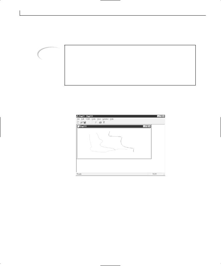
236 |
Day 11 |
When you use the ON_COMMAND_RANGE message-map entry, the event message ID is automatically passed as an argument to the event-handler function. This allows you to
Note
The message map is a mechanism used by Visual C++ and MFC to easily specify event messages and the functions that should be called to handle the event. These message-map commands are converted by the Visual C++ compiler into a fast and efficient map for calling the appropriate event functions when a message is received by the application. Whenever you add a function through the Class Wizard, you are not only adding the function to the code, but you are also adding an entry into the message map for that class.
create the function in Listing 11.3 to handle the color selection event messages. If you compile and run your application at this point, you should find that the color selection functionality is all working just as it did yesterday, as shown in Figure 11.3.
FIGURE 11.3.
Running the MDI application.
Adding a Context Menu
In most Windows applications, you can right-click the mouse and what is known as a context menu, or pop-up menu, appears. Back on Day 6, “Creating Menus for Your Application,” you implemented a simple pop-up menu. However, there is a mechanism for creating and using these context menus when Windows thinks that the menu should be opened. This process allows you to add context menus that behave more consistently with other Windows applications (and if Microsoft changes how the context menus are triggered with a new version of Windows, yours will still behave according to the
Creating Multiple Document Interface Applications |
237 |
Windows standard).
An event message WM_CONTEXTMENU is passed to the event queue when the right mouse button is released or when the context menu button is pressed (if you have a newer Windows-enabled keyboard with the context menu button). If you place an event-handler function on the WM_CONTEXTMENU event message, you can display a pop-up menu with confidence that you are showing it at the appropriate time.
To add the context menu to your application, you create a new menu for use as the context menu. To do this, follow these steps:
1. |
In the Resource View tab on the workspace pane, right-click the Menu folder. |
|
2. |
Select Insert Menu from the pop-up menu (or should I say context menu). |
|
3. |
Select the new menu (still in the workspace pane), open its properties dialog, and |
|
|
name the menu IDR_CONTEXTMENU. |
|
4. |
In the Menu Designer, specify the top-level menu caption as a single space. This |
|
|
causes Visual C++ to add the first entry in the drop-down portion of the menu. |
|
5. |
In the first drop-down menu entry, specify the caption as &Width and check the |
|
|
Pop-up check box. (This causes the ID combo box to be disabled and an arrow to |
11 |
|
display beside the caption, along with another menu entry to the right of the menu |
entry you are modifying.)
6.Do not add any menu entries into the Width cascading menu at this time (that is left for an exercise at the end of the chapter). Instead, select the menu entry below the Width entry and open its properties dialog. Specify the caption as &Colors and check the Pop-up check box.
7.In the colors cascading menu, add the color menu entries as you did for the IDR_DAY11TYPE menu, using the same property settings. You can select the ID from the drop-down list of IDs, if you would rather search for them instead of type. When you finish, your menu should look like the one in Figure 11.4.
8.Select the Class View tab in the workspace pane.
9.Select the CDay11View class. Open the Class Wizard by selecting View | ClassWizard from the menu.
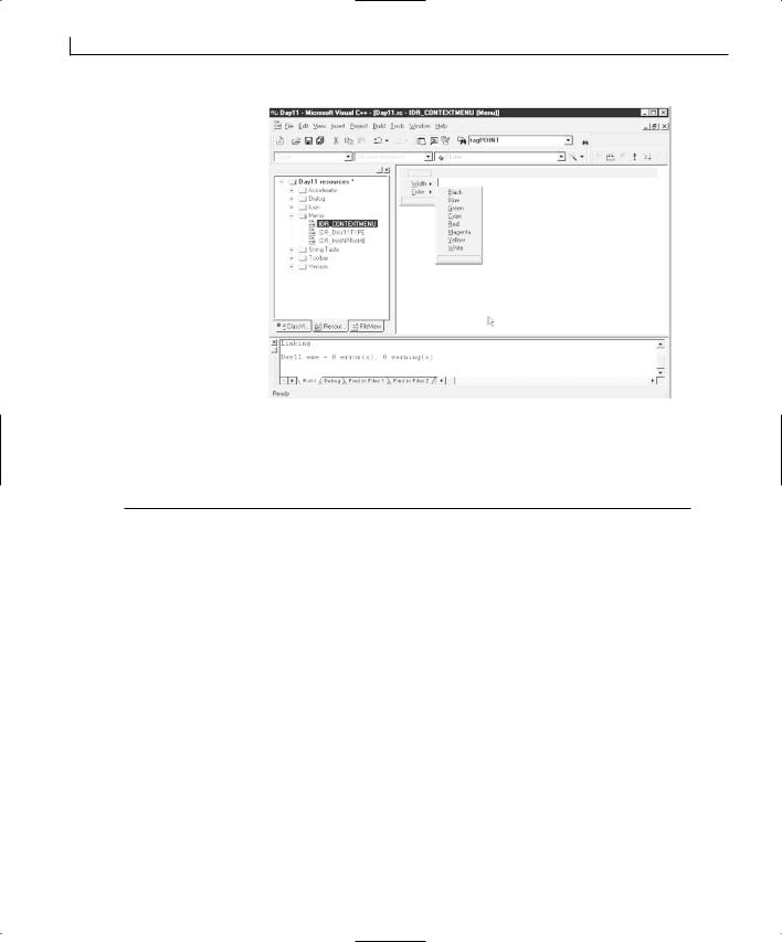
238 |
Day 11 |
FIGURE 11.4.
The context menu design.
10.Add a function for the WM_CONTEXTMENU event message on the CDay11View class.
11.Edit the function, adding the code in Listing 11.4.
LISTING 11.4. THE CDay11View OnContextMenu FUNCTION.
1:void CDay11View::OnContextMenu(CWnd* pWnd, CPoint point)
2:{
3:// TODO: Add your message handler code here
4:
5:///////////////////////
6:// MY CODE STARTS HERE
7:///////////////////////
9: CMenu menu; 10:
11:// Load the context menu
12:menu.LoadMenu(IDR_CONTEXTMENU);
13:// Get the first sub menu (the real menu)
14:CMenu *pContextMenu = menu.GetSubMenu(0);
16:// Display the context menu for the user
17:pContextMenu->TrackPopupMenu(TPM_LEFTALIGN |
18:TPM_LEFTBUTTON | TPM_RIGHTBUTTON,
19:point.x, point.y, AfxGetMainWnd());
20:
21:///////////////////////
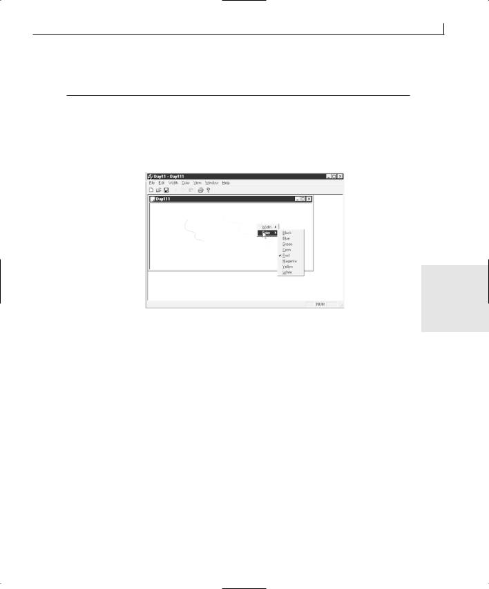
Creating Multiple Document Interface Applications |
239 |
22:// MY CODE ENDS HERE
23:///////////////////////
24:}
This code should all look familiar to you from what you learned on Day 6. If you compile and run your application now, you should be able to click your right mouse button on the child window and change your drawing color from the context menu that opened, as shown in Figure 11.5.
FIGURE 11.5.
Using the context menu to change drawing colors.
11
Summary
That wasn’t too bad; was it? After yesterday, you probably needed the easy day today, along with all the review of what you did yesterday to help it all sink in. But you did get to learn some new things today. You learned about MDI applications, what they are, and how they differ from SDI applications. You learned how you could take a series of menus and use a single event-handler function for all of them. You also learned how you can create a menu specifically for use as a pop-up context menu and how you can integrate it into an MDI application.
Q&A
QBecause it’s basically the same code to create an MDI or SDI application, why would I want to create an SDI application? Why wouldn’t I want to make all my applications MDI applications?
AIt depends on the application and how it’s going to be used. You probably use both types of applications on a daily basis. If you are writing a memo or working on a

240 |
Day 11 |
spreadsheet, you are probably using an MDI application. If you are browsing the World Wide Web, your Web browser is most likely an SDI application. A simple text editor such as Notepad would probably be more difficult for the user as an MDI style application, but as an SDI application, it’s just about right (for the task it handles). Certain applications make more sense implemented as an SDI application than as an MDI application. You need to think through how your application is going to be used and determine which model it’s more suited for.
QSome entries on my color menu are changing to the wrong color. How can I determine the problem?
AThe problem is that the color menu IDs are probably not in sequential order or are out of order. You can check them by right-clicking on the Day11 resources in the Resource View tab of the workspace pane. Select Resource Symbols from the popup menu to display a list of the IDs and the numbers assigned to them in alphabetical order. Start with the Black ID and make sure that the numbers increase by 1 without skipping any numbers. Be sure to check these IDs in the order that the colors appear on the menu (and in the color table in the Day11Doc.cpp file), not in the alphabetical order in which they are displayed in this list. If you find some errors, you have to close Visual C++ and open the Resource.h file in a text editor to renumber the IDs correctly. Once you make the corrections (be sure to delete any duplicates), save your corrections, restart Visual C++, and recompile your application. The color menu should work correctly.
Workshop
The Workshop provides quiz questions to help you solidify your understanding of the material covered and exercises to provide you with experience in using what you’ve learned. The answers to the quiz questions and exercises are provided in Appendix B, “Answers.”
Quiz
1.What are the five base classes that are used in MDI applications?
2.Why do you have to place the ON_COMMAND_RANGE message map entry outside the section maintained by the Class Wizard?
3.What argument does ON_COMMAND_RANGE pass to the event function?
4.What event message should you use to display a pop-up menu?
Creating Multiple Document Interface Applications |
241 |
Exercise
Add the pull-down and context menus for the width, using the same pen widths as yesterday.
11


WEEK 2
DAY 12
Adding Toolbars and
Status Bars
When you created your SDI and MDI applications, they not only came with default menus already attached, but also they came with simple toolbars to go with the menus. These simple toolbars had the standard set of functions (New, Open, Save, Print, Cut, Copy, and Paste) that are on the toolbars of most Windows applications. Most applications don’t limit their toolbars to just this standard selection of functions but have customized toolbars that reflect the specific functionality of the application.
In addition to the toolbars, the SDI and MDI applications have a status bar at the bottom of the frame that provides textual descriptions of the toolbar buttons and menu entries. The status bar also has default areas that display whether the Caps, Num, and Scroll Lock keys are on.
Today, you will learn
●How to design your own toolbar.
●How to attach your toolbar to the application frame.

244 |
Day 12 |
●How to show and hide your toolbar with a menu entry.
●How to place a combo box on your toolbar.
●How to display descriptions of your toolbar entries in the status bar.
●How to add your own status bar elements.
Toolbars, Status Bars, and Menus
One of the driving intentions behind the development of Graphical User Interfaces (GUI) such as Windows was the goal of making computers easier to use and learn. In the effort to accomplish this goal, GUI designers stated that all applications should use a standard set of menus and that the menus should be organized in a standardized manner. When Microsoft designed the Windows operating system, it followed this same philosophy, using a standard set of menus organized in a standard order on most of its applications.
A funny thing happened once Windows became widely used. The application designers found that new users still had a difficult time learning new applications and that advanced users found the menus cumbersome. As a result, the application designers invented toolbars as one solution to both problems.
A toolbar is a small band attached to the window frame or a dialog window that is floating independent of the application frame. This band (or dialog) has a number of small buttons containing graphic images that can be used in place of the menus. The application designers place the most commonly used functions for their applications on these toolbars and do their best to design graphical images that illustrate the functions the buttons serve.
Once advanced users learned what each of the toolbar buttons do, the toolbars were a hit. However, novice users still had problems learning what the toolbar does. As a result, the application designers went back to the drawing board to come up with ways to help the new user learn how use the toolbar buttons.
One of the solutions was to use the information bar that many of them had begun placing at the bottom of application windows to provide detailed descriptions of both menu entries and toolbar buttons. One of the other solutions was to provide a little pop-up window with a short description of the button that appears whenever the mouse is positioned over the button for more than a couple of seconds. The first of these solutions became known as the status bar, and the second became known as tooltips. Both solutions are in common practice with most Windows applications today.
If you want to design and use your own toolbars and status bars in your applications, you might think that Visual C++ provides plenty of support for your efforts and even makes it
Adding Toolbars and Status Bars |
245 |
easy to implement. After all, Microsoft’s own application developers have been in the forefront of developing these elements, and most, if not all, of Microsoft’s Windows applications are developed using its own Visual C++. Well, you are correct in making that assumption, and today, you’ll learn how to create your own custom toolbars and status bars for your applications.
Designing a Toolbar
For learning how to create your own toolbar, you will modify the application that you created on Day 10, “Creating Single Document Interface Applications,” the SDI drawing application, to add a toolbar for selecting the color to use in drawing.
Note
Although the sample application you are working with today is an extension to the application you built on Day 10, all file and class names have been changed from Day10 to Toolbar. If you are making the changes in the Day 10 project, then when the following text specifies that you make changes to the CToolbarDoc class, you should make the changes to the CDay10Doc class. Likewise, when you are asked to edit the Toolbar.rc file, you can edit the
Day10.rc file.
If all you want to do is add a few additional toolbar buttons to the default toolbar that the AppWizard creates when you start a new SDI or MDI application, you can pull up the
toolbar in the Visual C++ designer through the Resource View in the workspace pane 12 and begin adding new buttons. Just as in the Menu Designer, the end of the toolbar
always has a blank entry, waiting for you to turn it into another toolbar button, as shown in Figure 12.1. All you have to do is select this blank button, drag it to the right if you want a separator between it and the button beside it, or drag it to a different position if you want it moved. After you have the button in the desired location, you paint an icon on the button that illustrates the function that the button will trigger. Finally, double-click the button in the toolbar view to open the button’s properties dialog and give the button the same ID as the menu that it will trigger. The moment that you compile and run your application, you will have a new toolbar button that performs a menu selection that you chose. If you want to get rid of a toolbar button, just grab it on the toolbar view, and drag it off the toolbar.
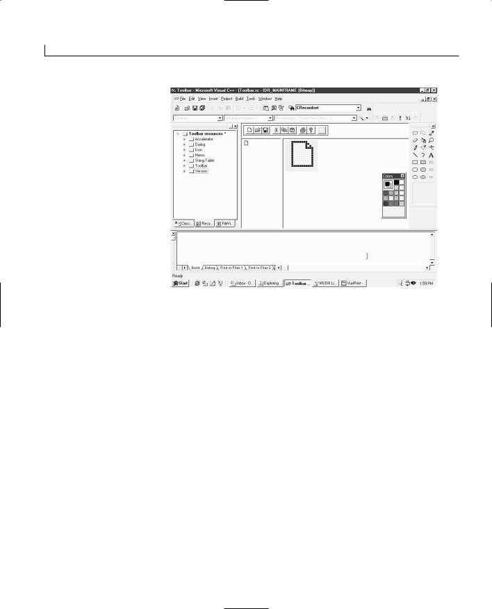
246 |
Day 12 |
FIGURE 12.1.
The toolbar designer.
Creating a New Toolbar
To insert a new toolbar, right-click on the Toolbar folder and select Insert Toolbar from the pop-up menu. This creates an empty toolbar with a single blank button. As you start drawing an icon on each of the blank buttons in the toolbar, another blank button is added on the end.
For use in your drawing application, fill eight buttons with the eight colors available in the drawing application.
Once you draw icons on each of the buttons in your toolbar, double-click on the first button in the toolbar view. This should open the toolbar button properties dialog. In the ID field, enter (or select from the drop-down list) the ID of the menu that this toolbar button should trigger. In the Prompt field, enter the description that should appear in the status bar for this toolbar button. (If you entered a prompt for the menu, then this field is automatically populated with the menu description.) At the end of the status bar description, add \n and a short description to appear in the tooltips for the toolbar button.
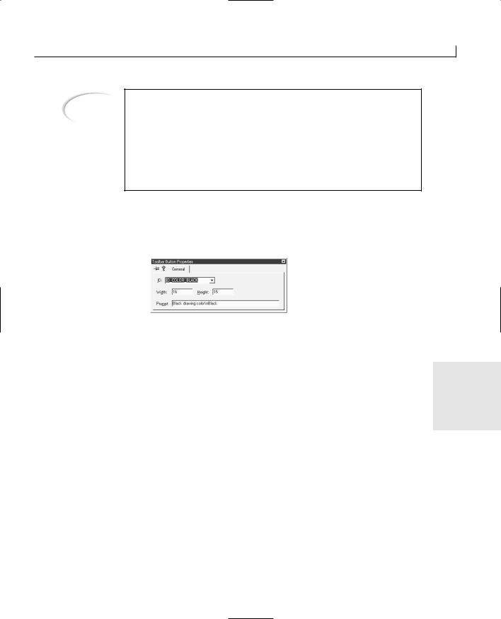
Adding Toolbars and Status Bars |
247 |
Note
In C/C++, the \n string is a shorthand notation for “begin a new line.” In the prompt for toolbar buttons and menu entries, this string is used to separate the status bar descriptions of the menu entries and the tooltips pop-up prompt that appears when the mouse is held over a toolbar button for a few seconds. The first line of the prompt is used for the status bar description, and the second line is used for the tooltips description. The tooltips description is only used with the toolbars, so there’s no reason to add this for menu entries that will have no toolbar equivalents.
For example, for the black application, enter an ID of as shown in Figure 12.2.
button on the toolbar that you are creating for your drawing
ID_COLOR_BLACK and a prompt of Black drawing color\nBlack,
FIGURE 12.2.
The toolbar button properties dialog.
Once you finish designing your toolbar and have icons on all of your buttons with the properties set for each button, you will change the toolbar ID. In the workspace pane, right-click the new toolbar that you just added and open its properties dialog. Change the
toolbar ID to a descriptive name.
12
As an example, for the color toolbar that you created for your drawing application, change the toolbar ID to IDR_TBCOLOR.
Attaching the Toolbar to the Application Frame
In the previous SDI and MDI applications, you didn’t add any functionality that required you to touch the frame window. Well, because the toolbar is attached to the frame, you’ll have to begin adding and modifying code in that module. If you open the CMainFrame class to the OnCreate function, you’ll see where it’s creating the existing toolbar and then later in this function where the toolbar is being attached to the frame.
Before you can add your toolbar to the application frame, you need to add a variable to the CMainFrame class to hold the new toolbar. This variable of type CToolBar should be protected in accessibility.

248 |
Day 12 |
To add your color toolbar to your draw application, right-click the CMainFrame class in the Class View tab of the workspace pane. Select Add Member Variable from the pop-up menu, and specify the variable type as CToolBar, the name as m_wndColorBar, and the access as protected.
After you add a variable for your toolbar, you need to add some code in the OnCreate function in the CMainFrame class to add the toolbar and attach it to the frame. Make the modifications in Listing 12.1 to add the color toolbar to your drawing application.
LISTING 12.1. THE MODIFIED C MainFrame.OnCreate FUNCTION.
1:int CMainFrame::OnCreate(LPCREATESTRUCT lpCreateStruct)
2:{
3:if (CFrameWnd::OnCreate(lpCreateStruct) == -1)
4:return -1;
5:
6:if (!m_wndToolBar.CreateEx(this, TBSTYLE_FLAT,WS_CHILD | WS_VISIBLE | CBRS_TOP
7:| CBRS_GRIPPER | CBRS_TOOLTIPS | CBRS_FLYBY |CBRS_SIZE_DYNAMIC) ||
8:!m_wndToolBar.LoadToolBar(IDR_MAINFRAME))
9:{
10:TRACE0(“Failed to create toolbar\n”);
11:return -1; // fail to create
12:}
13:
14:///////////////////////
15:// MY CODE STARTS HERE
16:///////////////////////
18:// Add the color toolbar
19:int iTBCtlID;
20:int i;
21:
22:// Create the Color Toolbar
23:if (!m_wndColorBar.CreateEx(this, TBSTYLE_FLAT, WS_CHILD |
24:WS_VISIBLE | CBRS_TOP | CBRS_GRIPPER | CBRS_TOOLTIPS |
25:CBRS_FLYBY | CBRS_SIZE_DYNAMIC) ||
26:!m_wndColorBar.LoadToolBar(IDR_TBCOLOR))
27:{
28:TRACE0(“Failed to create toolbar\n”);
29:return -1; // fail to create
30:}
31:// Find the Black button on the toolbar
32:iTBCtlID = m_wndColorBar.CommandToIndex(ID_COLOR_BLACK);
33:if (iTBCtlID >= 0)
34:{
Adding Toolbars and Status Bars
35:// Loop through the buttons, setting them to act as radiobuttons
36:for (i= iTBCtlID; i < (iTBCtlID + 8); i++)
37:m_wndColorBar.SetButtonStyle(i, TBBS_CHECKGROUP);
38:}
39:
40:///////////////////////
41:// MY CODE ENDS HERE
42:///////////////////////
44:if (!m_wndStatusBar.Create(this) ||
45:!m_wndStatusBar.SetIndicators(indicators,
46:sizeof(indicators)/sizeof(UINT)))
47:{
48:TRACE0(“Failed to create status bar\n”);
49:return -1; // fail to create
50:}
51:
52:// TODO: Delete these three lines if you don’t want the toolbar to
53:// be dockable
54:m_wndToolBar.EnableDocking(CBRS_ALIGN_ANY);
55:
56:///////////////////////
57:// MY CODE STARTS HERE
58:///////////////////////
60:// Enable docking for the Color Toolbar
61:m_wndColorBar.EnableDocking(CBRS_ALIGN_ANY);
63:///////////////////////
64:// MY CODE ENDS HERE
65:///////////////////////
67:EnableDocking(CBRS_ALIGN_ANY);
68:DockControlBar(&m_wndToolBar);
70:///////////////////////
71:// MY CODE STARTS HERE
72:///////////////////////
74:// Dock the Color Toolbar
75:DockControlBar(&m_wndColorBar);
77:///////////////////////
78:// MY CODE ENDS HERE
79:///////////////////////
81:return 0;
82:}
249
12

250 |
Day 12 |
Creating the Toolbar
The first part of the code you added,
if (!m_wndColorBar.CreateEx(this, TBSTYLE_FLAT, WS_CHILD | WS_VISIBLE | CBRS_TOP | CBRS_GRIPPER | CBRS_TOOLTIPS | CBRS_FLYBY | CBRS_SIZE_DYNAMIC) || !m_wndColorBar.LoadToolBar(IDR_TBCOLOR))
contains two separate functions that are necessary in creating a toolbar. The first function, CreateEx, creates the toolbar itself, whereas the second, LoadToolBar, loads the toolbar that you designed in the toolbar designer. The second function, LoadToolBar, requires a single argument, the ID for the toolbar that you want to create.
The CreateEx function has several arguments that you can pass with the function. The first argument, and the only required argument, is a pointer to the parent window. In this case (which is normally the case), this argument is a pointer to the frame window to which the toolbar will be attached.
The second argument is the style of controls on the toolbar that is to be created. Several toolbar control styles are available for use, some of which have been introduced with the last two versions of Internet Explorer. Table 12.1 lists the available styles.
TABLE 12.1. TOOLBAR CONTROL STYLES.
Style |
Description |
TBSTYLE_ALTDRAG
Allows the user to move the toolbar by dragging it while holding down the Alt key.
TBSTYLE_CUSTOMERASE |
Generates a NM_CUSTOMDRAW message when erasing the toolbar |
|
and button background, allowing the programmer to choose when |
|
and whether to control the background erasing process. |
TBSTYLE_FLAT
TBSTYLE_LIST
TBSTYLE_REGISTERDROP
TBSTYLE_TOOLTIPS
TBSTYLE_TRANSPARENT
TBSTYLE_WRAPABLE
Creates a flat toolbar. Button text appears under the bitmap image.
Button text appears to the right of the bitmap image.
For use in dragging and dropping objects onto toolbar buttons.
Creates a tooltip control that can be used to display descriptive text for the buttons.
Creates a transparent toolbar.
Creates a toolbar that can have multiple rows of buttons.
The third argument is the style of the toolbar itself. This argument is normally a combination of window and control bar styles. Normally, only two or three window styles are used, and the rest of the toolbar styles are control bar styles. The list of the normally used toolbar styles appears in Table 12.2.
Adding Toolbars and Status Bars |
251 |
TABLE 12.2. TOOLBAR STYLES.
Style |
Description |
WS_CHILD
WS_VISIBLE
CBRS_ALIGN_TOP
CBRS_ALIGN_BOTTOM
CBRS_ALIGN_LEFT
CBRS_ALIGN_RIGHT
CBRS_ALIGN_ANY
CBRS_BORDER_TOP
CBRS_BORDER_BOTTOM
CBRS_BORDER_LEFT
CBRS_BORDER_RIGHT
CBRS_FLOAT_MULTI
CBRS_TOOLTIPS
CBRS_FLYBY
CBRS_GRIPPER
The toolbar is created as a child window.
The toolbar will be visible when created.
Allows the toolbar to be docked to the top of the view area of the frame window.
Allows the toolbar to be docked to the bottom of the view area of the frame window.
Allows the toolbar to be docked to the left side of the view area of the frame window.
Allows the toolbar to be docked to the right side of the view area of the frame window.
Allows the toolbar to be docked to any side of the view area of the frame window.
Places a border on the top edge of the toolbar when the top of the toolbar is not docked.
Places a border on the bottom edge of the toolbar when the top of the toolbar is not docked.
Places a border on the left edge of the toolbar when the top of the toolbar is not docked.
Places a border on the right edge of the toolbar when the top of the toolbar is not docked.
Allows multiple toolbars to be floated in a single miniframe |
12 |
|
|
window. |
|
Causes tooltips to be displayed for the toolbar buttons. |
|
Causes status bar message text to be updated for the toolbar but- |
|
tons at the same time as the tooltips. |
|
Causes a gripper to be drawn on the toolbar. |
|
The fourth argument, which you did not provide in your code, is the size of the toolbar borders. This argument is passed as a standard CRect rectangle class to provide the length and height desired for the toolbar. The default value is 0 for all of the rectangle dimensions, thus resulting in a toolbar with no borders.
The fifth and final argument, which you also did not provide in your code, is the toolbar’s child window ID. This defaults to AFX_IDW_TOOLBAR, but you can specify any defined ID that you need or want to use for the toolbar.

252 |
Day 12 |
Setting the Button Styles
After you create the toolbar, there is a curious bit of code:
// Find the Black button on the toolbar
iTBCtlID = m_wndColorBar.CommandToIndex(ID_COLOR_BLACK); if (iTBCtlID >= 0)
{
// Loop through the buttons, setting them to act as radio buttons for (i= iTBCtlID; i < (iTBCtlID + 8); i++)
m_wndColorBar.SetButtonStyle(i, TBBS_CHECKGROUP);
}
The first line in this code snippet uses the CommandToIndex toolbar function to locate the control number of the ID_COLOR_BLACK button. If you design your toolbar in the order of colors that you used on the menu, this should be the first control, with a index of 0. It’s best to use the CommandToIndex function to locate the index of any toolbar button that you need to alter, just in case it’s not where you expect it to be. This function returns the index of the toolbar control specified, and you use this as a starting point to specify the button style of each of the color buttons.
In the loop, where you are looping through each of the eight color buttons on the toolbar, you use the SetButtonStyle function to control the behavior of the toolbar buttons. The first argument to this function is the index of the button that you are changing. The second argument is the style of button that you want for the toolbar button specified. In this case, you are specifying that each of the buttons be TBBS_CHECKGROUP buttons, which makes them behave like radio buttons, where only one of the buttons in the group can be selected at any time. The list of the available button styles is in Table 12.3.
TABLE 12.3. TOOLBAR BUTTON STYLES.
Style |
Description |
TBSTYLE_AUTOSIZE
TBSTYLE_BUTTON
TBSTYLE_CHECK
The button’s width will be calculated based on the text on the button.
Creates a standard push button.
Creates a button that acts like a check box, toggling between the pressed and unpressed state.
TBSTYLE_CHECKGROUP
TBSTYLE_DROPDOWN
TBSTYLE_GROUP
Creates a button that acts like a radio button, remaining in the pressed state until another button in the group is pressed. This is actually the combination of the TBSTYLE_CHECK and TBSTYLE_GROUP button styles.
Creates a drop-down list button.
Creates a button that remains pressed until another button in the group is pressed.
Adding Toolbars and Status Bars |
253 |
Style |
Description |
TBSTYLE_NOPREFIX
TBSTYLE_SEP
The button text will not have an accelerator prefix associated with it.
Creates a separator, making a small gap between the buttons on either side.
Docking the Toolbar
The last thing that you do in the code that you add to the OnCreate function in the CMainFrame class is the following:
// Enable docking for the Color Toolbar m_wndColorBar.EnableDocking(CBRS_ALIGN_ANY);
EnableDocking(CBRS_ALIGN_ANY); // (AppWizard generated line)
// Dock the Color Toolbar DockControlBar(&m_wndColorBar);
In the first of these lines, you called the EnableDocking toolbar function. This function enables the toolbar for docking with the frame window. The value passed to this toolbar function must match the value passed in the following EnableDocking function that is called for the frame window. The available values for these functions are listed in Table 12.4. These functions enable the borders of the toolbar, and the frame window, for docking. If these functions are not called, then you will not be able to dock the toolbar with the frame window. If a specific side is specified in these functions for use in docking, and the sides do not match, you will not be able to dock the toolbar with the frame.
12
TABLE 12.4. TOOLBAR DOCKING SIDES.
Style |
Description |
CBRS_ALIGN_TOP
Allows the toolbar to be docked to the top of the view area of the frame window.
CBRS_ALIGN_BOTTOM
Allows the toolbar to be docked to the bottom of the view area of the frame window.
CBRS_ALIGN_LEFT
Allows the toolbar to be docked to the left side of the view area of the frame window.
CBRS_ALIGN_RIGHT
Allows the toolbar to be docked to the right side of the view area of the frame window.
CBRS_ALIGN_ANY
Allows the toolbar to be docked to any side of the view area of the frame window.
CBRS_FLOAT_MULTI
0
Allows multiple toolbars to be floated in a single miniframe window.
The toolbar will not be able to dock with the frame.
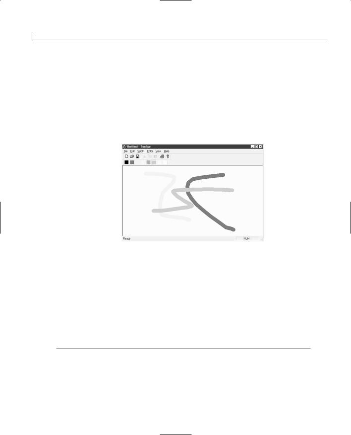
254 |
Day 12 |
The final function that you added was a frame window function, DockControlBar, which is passed the address of the toolbar variable. This function physically docks the toolbar to the frame window. Because all of this code appears in the OnCreate function for the frame window, the toolbar is docked before the user sees either the window or the toolbar.
Now, after adding all of this code to the OnCreate function of the CMainFrame class, if you compile and run your application, you’ll find a working color toolbar that you can use to select the drawing color, as shown in Figure 12.3.
FIGURE 12.3.
The color toolbar on the drawing program.
Controlling the Toolbar Visibility
Now that you have your color toolbar on the frame of your drawing application, it would be nice to be able to show and hide it just as you can the default toolbar and status bar through the View menu. This is simple enough functionality to add, but it doesn’t necessarily work the way you might expect it to.
The first thing you need to do is add a menu entry to toggle the visibility of the color bar. Do this through the Menu Designer, adding a new menu entry on the View menu. Specify the menu properties as shown in Table 12.5.
TABLE 12.5. COLOR BAR MENU PROPERTIES.
Property |
Setting |
ID |
ID_VIEW_COLORBAR |
Caption |
&Color Bar |
Prompt |
Show or hide the colorbar\nToggle ColorBar |
|
|

Adding Toolbars and Status Bars |
255 |
Updating the Menu
To determine whether the toolbar is visible or hidden, you can get the current style of the toolbar and mask out for the WS_VISIBLE style flag. If the flag is in the current toolbar style, then the toolbar is visible. By placing this evaluation into the SetCheck function in the UPDATE_COMMAND_UI event message handler, you can check and uncheck the color bar menu entry as needed.
To add this functionality to your drawing program, add an event handler for the UPDATE_COMMAND_UI event message on the ID_VIEW_COLOR menu. Be sure to add this event-handler function into the CMainFrame class. (You’re still making all of your coding changes so far in the frame class.) Edit the event-handler function, adding the code in Listing 12.2.
LISTING 12.2. THE MODIFIED C MainFrame.OnUpdateViewColorbar FUNCTION.
1:void CMainFrame::OnUpdateViewColorbar(CCmdUI* pCmdUI)
2:{
3:// TODO: Add your command update UI handler code here
4:///////////////////////
5:// MY CODE STARTS HERE
6:///////////////////////
7:
8:// Check the state of the color toolbar
9:pCmdUI->SetCheck(((m_wndColorBar.GetStyle() & WS_VISIBLE) != 0));
10:
11: |
/////////////////////// |
|
12: |
// MY CODE ENDS HERE |
12 |
13: |
/////////////////////// |
|
14: } |
|
|
Toggling the Toolbar Visibility
Because the CToolBar class is derived from the CWnd class (via the CControlBar class), you might think that you could call the ShowWindow function on the toolbar itself to show and hide the toolbar. Well, you can, but the background for the toolbar will not be hidden along with the toolbar. All the user would notice is the toolbar buttons appearing and disappearing. (Of course, this might be the effect you are after, but your users might not like it.)
Instead, you use a frame window function, ShowControlBar, to show and hide the toolbar. This function takes three arguments. The first argument is the address for the toolbar variable. The second argument is a boolean, specifying whether to show the toolbar.

256 |
Day 12 |
(TRUE shows the toolbar; FALSE hides the toolbar.) Finally, the third argument specifies whether to delay showing the toolbar. (TRUE delays showing the toolbar; FALSE shows the toolbar immediately.)
Once a toolbar is toggled on or off, you need to call another frame window function, RecalcLayout. This function causes the frame to reposition all of the toolbars, status bars, and anything else that is within the frame area. This is the function that causes the color toolbar to move up and down if you toggle the default toolbar on and off.
To add this functionality to your drawing program, add an event handler for the C O M- M A N D event message on the ID_VIEW_COLOR menu. Be sure to add this event-handler
function into the CMainFrame class. (You’re still making all of your coding changes so far in the frame class.) Edit the event-handler function, adding the code in Listing 12.3.
LISTING 12.3. THE MODIFIED C MainFrame.OnViewColorbar FUNCTION.
1:void CMainFrame::OnViewColorbar()
2:{
3:// TODO: Add your command handler code here
5:///////////////////////
6:// MY CODE STARTS HERE
7:///////////////////////
8:BOOL bVisible;
9:
10:// Check the state of the color toolbar
11:bVisible = ((m_wndColorBar.GetStyle() & WS_VISIBLE) != 0);
13:// Toggle the color bar
14:ShowControlBar(&m_wndColorBar, !bVisible, FALSE);
15:// Reshuffle the frame layout
16:RecalcLayout();
17:
18:///////////////////////
19:// MY CODE ENDS HERE
20:///////////////////////
21:}
At this point, after compiling and running your application, you should be able to toggle your color toolbar on and off using the View menu.

Adding Toolbars and Status Bars |
257 |
Adding a Combo Box to a Toolbar
It’s commonplace now to use applications that have more than just buttons on toolbars. Look at the Visual C++ Developer Studio, for example. You’ve got combo boxes that enable you to navigate through your code by selecting the class, ID, and function to edit right on the toolbar. So how do you add a combo box to a toolbar? It’s not available in the toolbar designer; all you have there are buttons that you can paint icons on. You can’t add a combo box to any toolbar by using any of the Visual C++ wizards. You have to write a little C++ code to do it.
To learn how to add a combo box to a toolbar, you’ll add a combo box to the color toolbar you just created. The combo box will be used to select the width of the pen the user will use to draw images. (If you haven’t added the support for different drawing widths from the exercise at the end of Day 10, you might want to go back and add that now.)
Editing the Project Resources
To add a combo box to your toolbar, the first thing that you need to do is what Visual C++ was designed to prevent you from having to do. You need to edit the resource file yourself. You cannot do this through the Visual C++ Developer Studio. If you try to open the resource file in the Developer Studio, you will be popped into the Resource View tab of the workspace pane, editing the resource file through the various resource editors and designers. No, you’ll have to edit this file in another editor, such as Notepad.
Close Visual C++, the only way to guarantee that you don’t write over your changes. Open Notepad and navigate to your project directory. Open the resource file, which is
named after the project with a .rc filename extension. Once you open this file in Notepad, 12 scroll down until you find the toolbar definitions. (You can search for the word “tool-
bar.”) Once you’ve found the toolbar definitions, go to the end of the Color toolbar definition and add two separator lines at the bottom of the toolbar definition.
For instance, to make these changes to your drawing application, you need to navigate to the Toolbar project directory and then open the Toolbar.rc file. (If you are adding these toolbars to the MDI drawing application, you need to look for the Day11.rc file.) Search for the toolbar section, and then add two SEPARATOR lines just before the end of the IDR_TBCOLOR section, as shown in Listing 12.4. Once you add these two lines, save the file, exit Notepad, and restart Visual C++, reloading the project.

258 |
Day 12 |
LISTING 12.4. THE MODIFIED PROJECT RESOURCE FILE (Toolbar.rc).
1://////////////////////////////////////////////////////////////////////
2://
3:// Toolbar
4://
5:
6:IDR_MAINFRAME TOOLBAR DISCARDABLE 16, 15
7:BEGIN
8: |
BUTTON |
ID_FILE_NEW |
9: |
BUTTON |
ID_FILE_OPEN |
10: |
BUTTON |
ID_FILE_SAVE |
11:SEPARATOR
12: |
BUTTON |
ID_EDIT_CUT |
13: |
BUTTON |
ID_EDIT_COPY |
14: |
BUTTON |
ID_EDIT_PASTE |
15:SEPARATOR
16: |
BUTTON |
ID_FILE_PRINT |
17: |
BUTTON |
ID_APP_ABOUT |
18: END |
|
|
19: |
|
|
20:IDR_TBCOLOR TOOLBAR DISCARDABLE 16, 15
21:BEGIN
22: |
BUTTON |
ID_COLOR_BLACK |
23: |
BUTTON |
ID_COLOR_BLUE |
24: |
BUTTON |
ID_COLOR_GREEN |
25: |
BUTTON |
ID_COLOR_CYAN |
26: |
BUTTON |
ID_COLOR_RED |
27: |
BUTTON |
ID_COLOR_MAGENTA |
28: |
BUTTON |
ID_COLOR_YELLOW |
29: |
BUTTON |
ID_COLOR_WHITE |
30:SEPARATOR
31:SEPARATOR
32:END
You added these two SEPARATOR lines in the toolbar definition so that the second separator can act as a place holder for the combo box that you are going to add to the toolbar. There are two reasons that you had to make this edit by hand and not use the Visual C++ toolbar designer. The first reason is that the toolbar designer would not allow you to add more than one separator to the end of the toolbar. The second reason is that, if you don’t add anything else on the end of your toolbar after the separator, the toolbar designer decides that the separator is a mistake and removes it for you. In other words, the Visual C++ toolbar designer does not allow you to add the place holder for the combo box to your toolbar.
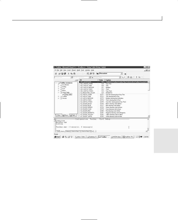
Adding Toolbars and Status Bars |
259 |
Next, you need to add the text strings that you will load into your combo box. To add these strings, you need to open the string table in the Resource View of the workspace pane. Here you find all of the strings that you entered as prompts in various properties dialogs. This table has a number of IDs, the values of those IDs, and textual strings that are associated with those IDs, as shown in Figure 12.4. You’ll need to add the strings to be placed into your toolbar combo box in the string table; each line in the drop-down list must have a unique ID and entry in the strings table.
FIGURE 12.4.
The string table editor.
12
For instance, to add the strings for the combo box that you will be adding to the color toolbar, insert a new string, either by selecting Insert|New String from the menu or by right-clicking the string table and selecting New String from the pop-up menu.
In the String properties dialog, specify a string ID for the string and then enter the string to appear in the drop-down list. Close the properties dialog to add the string. For the strings in the Width combo box that you are going to add to the color toolbar, add the strings in Table 12.6.

260 |
Day 12 |
TABLE 12.6. WIDTH TOOLBAR COMBO BOX STRINGS.
ID |
Caption |
IDS_WIDTH_VTHIN |
Very Thin |
IDS_WIDTH_THIN |
Thin |
IDS_WIDTH_MEDIUM |
Medium |
IDS_WIDTH_THICK |
Thick |
IDS_WIDTH_VTHICK |
Very Thick |
|
|
Creating the Toolbar Combo Box
Before you can add the combo box to the color toolbar, you need to create a combo box variable that you can use for the combo box. Because you are not able to add this combo box through any of the designers, you need to add it as a variable to the CMainFrame class.
To add the combo box variable to the main frame class for the color toolbar, select the Class View tab in the workspace pane. Right-click the CMainFrame class and select Add Member Variable from the pop-up menu. Specify the variable type as CComboBox, the name as m_ctlWidth, and the access as protected.
Once you add the combo box variable to the main frame class, you need to perform a series of actions, all once the toolbar has been created:
1.Set the width and the ID of the combo box place holder on the toolbar to the width and ID of the combo box.
2.Get the position of the toolbar placeholder and use it to size and position the combo box.
3.Create the combo box, specifying the toolbar as the parent window of the combo box.
4.Load the strings into the drop-down list on the combo box.
To organize this so that it doesn’t get too messy, it might be advisable to move the creation of the color toolbar to its own function that can be called from the OnCreate function of the main frame class. To create this function, right-click the CMainFrame class in the workspace pane and select Add Member Function from the pop-up menu. Specify the function type as BOOL, the function description as CreateColorBar, and the access as public. Edit the new function, adding the code in Listing 12.5.
Adding Toolbars and Status Bars
LISTING 12.5. THE C MainFrame CreateColorBar FUNCTION.
1:BOOL CMainFrame::CreateColorBar()
2:{
3:int iTBCtlID;
4:inti;
5:
6:if (!m_wndColorBar.CreateEx(this, TBSTYLE_FLAT,WS_CHILD | WS_VISIBLE | CBRS_TOP
7:| CBRS_GRIPPER | CBRS_TOOLTIPS | CBRS_FLYBY |CBRS_SIZE_DYNAMIC) ||
8:!m_wndColorBar.LoadToolBar(IDR_TBCOLOR))
9:{
10:TRACE0(“Failed to create toolbar\n”);
11: |
return FALSE; |
// fail to create |
12:}
13:iTBCtlID = m_wndColorBar.CommandToIndex(ID_COLOR_BLACK);
14:if (iTBCtlID >= 0)
15:{
16:for (i= iTBCtlID; i < (iTBCtlID + 8); i++)
17:m_wndColorBar.SetButtonStyle(i, TBBS_CHECKGROUP);
18:}
19:// Add the Combo
20:int nWidth = 100;
21:int nHeight = 125;
22:
23:// Configure the combo place holder
24:m_wndColorBar.SetButtonInfo(9, IDC_CBWIDTH, TBBS_SEPARATOR,nWidth);
25:
26:// Get the colorbar height
27:CRect rect;
28:m_wndColorBar.GetItemRect(9, &rect);
29:rect.bottom = rect.top + nHeight;
30:
31:// Create the combo box
32:m_ctlWidth.Create(WS_CHILD | WS_VISIBLE | WS_VSCROLL |
33:CBS_DROPDOWNLIST, rect, &m_wndColorBar, IDC_CBWIDTH);
35:// Fill the combo box
36:CString szStyle;
37:if (szStyle.LoadString(IDS_WIDTH_VTHIN))
38:m_ctlWidth.AddString((LPCTSTR)szStyle);
39:if (szStyle.LoadString(IDS_WIDTH_THIN))
40:m_ctlWidth.AddString((LPCTSTR)szStyle);
41:if (szStyle.LoadString(IDS_WIDTH_MEDIUM))
42:m_ctlWidth.AddString((LPCTSTR)szStyle);
43:if (szStyle.LoadString(IDS_WIDTH_THICK))
261
12
continues

262 |
Day 12 |
LISTING 12.5. CONTINUED
44:m_ctlWidth.AddString((LPCTSTR)szStyle);
45:if (szStyle.LoadString(IDS_WIDTH_VTHICK))
46:m_ctlWidth.AddString((LPCTSTR)szStyle);
48:return TRUE;
49:}
On line 24 in Listing 12.5, you specify that the combo box should be created using the object ID IDC_CBWIDTH. This object ID is used to identify the combo box when the combo box sends an event message to the application or when you need to specify what list entry is displayed in the edit field. However, this object ID doesn’t exist in your application. Before you can compile the application, you’ll need to add this ID to the project resource IDs, just as you did on Day 4, “Working with Timers.” To add this ID to your project, select the Resource view in the workspace pane. Select the top of the resource tree and right-click the mouse to trigger the context menu. Select Resource Symbols from the pop-up menu and add the object ID IDC_CBWIDTH. Make sure that you add the new object ID with a unique numerical value so that it won’t conflict with any other objects in use in your application.
Configuring the Placeholder
After creating the toolbar and configuring all of the toolbar buttons, the first thing you need to do is to configure the separator that is acting as the place holder for the combo box you are about to create. You do this with the SetButtonInfo toolbar function, as follows:
m_wndColorBar.SetButtonInfo(9, IDC_CBWIDTH, TBBS_SEPARATOR, nWidth);
This function takes four arguments. The first argument is the current index of the control in the toolbar—in this case, the tenth control in the toolbar (eight color buttons and two separators). The second argument is the new ID of the toolbar control. This is the ID that will be placed in the event message queue when a control event occurs. The third argument is the type of toolbar control this control should be. The fourth and final argument is somewhat deceptive. If you look at the function documentation, the fourth argument is the new index of the control in the toolbar. This is the position to which the control will be moved. However, if the control is a separator, this argument specifies the width of the control and doesn’t move it anywhere. Because this toolbar control is a separator, this argument has the effect of setting it to be as wide as the combo box that you are going to create.
Adding Toolbars and Status Bars |
263 |
Getting the Toolbar Combo Box Position
Now that you have configured the toolbar separator as the place holder for the combo box, you need to get the position of the combo box place holder on the toolbar so that you can use it to set the position of the combo box:
m_wndColorBar.GetItemRect(9, &rect); rect.bottom = rect.top + nHeight;
In the first line, you called the toolbar function GetItemRect to get the position and size of the placeholder for the combo box. In the next line, you added the height of the dropdown list to the height that the combo box will eventually be.
Creating the Combo Box
Now that you’ve got a place holder sized correctly, and you have the position and size for the combo box, it’s time to create the combo box. You do this with the Create combo box function, as follows:
m_ctlWidth.Create(WS_CHILD | WS_VISIBLE | WS_VSCROLL |
CBS_DROPDOWNLIST, rect, &m_wndColorBar, IDC_CBWIDTH);
The first argument to the combo box Create function is the combo box style. Normally, several style flags are combined to create a combination style value. Table 12.7 lists the flags that you can use in this value.
TABLE 12.7. COMBO BOX STYLES.
Style |
Description |
WS_CHILD
WS_VISIBLE
WS_DISABLED
WS_VSCROLL
WS_HSCROLL
WS_GROUP
WS_TABSTOP
CBS_AUTOHSCROLL
Designates this as a child window (required). |
12 |
Makes the combo box visible.
Disables the combo box.
Adds vertical scrolling to the drop-down list.
Adds horizontal scrolling to the drop-down list.
Groups controls.
Includes the combo box in the tabbing order.
Automatically scrolls the text in the edit control to the right when the user types a character at the end of the line. This allows the user to enter text wider than the edit control into the combo box.
CBS_DROPDOWN |
Similar to CBS_SIMPLE, but the list is not displayed unless the user |
|
selects the icon next to the edit control. |
continues

264 |
Day 12 |
TABLE 12.7. CONTINUED
Style |
Description |
CBS_DROPDOWNLIST |
Similar to CBS_DROPDOWN, but the edit control is replaced with a |
|
static-text item displaying the currently selected item in the list. |
CBS_HASSTRINGS
The owner of the list box is responsible for drawing the list box contents. The list box items consist of strings.
CBS_OEMCONVERT
Text entered in the edit control is converted from ANSI to the OEM character set and then back to ANSI.
CBS_OWNERDRAWFIXED
CBS_OWNERDRAWVARIABLE
CBS_SIMPLE
CBS_SORT
CBS_DISABLENOSCROLL
CBS_NOINTEGRALHEIGHT
The owner of the list box is responsible for drawing the list box contents. The contents of the list are fixed in height.
The owner of the list box is responsible for drawing the list box contents. The contents of the list are variable in height.
The list box is displayed at all times.
Automatically sorts the strings in the list box.
List shows a disabled scrollbar when there are not enough items in the list to require scrolling.
Specifies that the combo box is exactly the size specified.
The second argument is the rectangle that the combo box is to occupy. This argument is the position within the parent window—in this case, the toolbar—that the combo box
will stay in. It will move with the parent window (the toolbar), staying in this position the entire time.
The third argument is a pointer to the parent window. This is the address of the color toolbar variable.
The fourth argument is the object ID for the combo box.
Populating the Combo Box
The final action that you have to do in creating the combo box on the color toolbar is populate the drop-down list with the available items that the user can select from. You do this with the combination of two functions:
if (szStyle.LoadString(IDS_WIDTH_VTHIN)) m_ctlWidth.AddString((LPCTSTR)szStyle);
The first function is a CString function, LoadString. This function takes a string ID and loads the string matching the ID from the string table. The second function is a combo box function, AddString, which adds the string passed in as an argument to the dropdown list. By calling this function combination for each of the elements that should be in the drop-down list, you can populate the combo box from the application string table.
Adding Toolbars and Status Bars |
265 |
Updating the OnCreate Function
After moving all of the code to create the color toolbar to a separate function, you can update the OnCreate function so that it calls the CreateColorBar function where it used to create the color toolbar, as in Listing 12.6.
LISTING 12.6. THE MODIFIED C MainFrame.OnCreate FUNCTION.
1:int CMainFrame::OnCreate(LPCREATESTRUCT lpCreateStruct)
2:{
3:if (CFrameWnd::OnCreate(lpCreateStruct) == -1)
4:return -1;
5:
6:if (!m_wndToolBar.CreateEx(this, TBSTYLE_FLAT,WS_CHILD | WS_VISIBLE | CBRS_TOP
7:| CBRS_GRIPPER | CBRS_TOOLTIPS | CBRS_FLYBY |CBRS_SIZE_DYNAMIC) ||
8:!m_wndToolBar.LoadToolBar(IDR_MAINFRAME))
9:{
10:TRACE0(“Failed to create toolbar\n”);
11:return -1; // fail to create
12:}
13:
14:///////////////////////
15:// MY CODE STARTS HERE
16:///////////////////////
18:// Add the color toolbar
19:if (!CreateColorBar())
20: |
{ |
|
12 |
21: |
TRACE0(“Failed to create color toolbar\n”); |
||
22: |
return -1; |
// fail to create |
|
23: |
} |
|
|
24: |
|
|
|
25:///////////////////////
26:// MY CODE ENDS HERE
27:///////////////////////
29:if (!m_wndStatusBar.Create(this) ||
30:!m_wndStatusBar.SetIndicators(indicators,
31:sizeof(indicators)/sizeof(UINT)))
32:{
33:TRACE0(“Failed to create status bar\n”);
34:return -1; // fail to create
35:}
36:
37:// TODO: Delete these three lines if you don’t want the toolbar to
38:// be dockable
39:m_wndToolBar.EnableDocking(CBRS_ALIGN_ANY);
continues
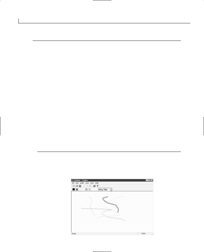
266 |
Day 12 |
LISTING 12.6. CONTINUED
40:
41:///////////////////////
42:// MY CODE STARTS HERE
43:///////////////////////
45:// Enable docking for the Color Toolbar
46:m_wndColorBar.EnableDocking(CBRS_ALIGN_ANY);
48:///////////////////////
49:// MY CODE ENDS HERE
50:///////////////////////
52:EnableDocking(CBRS_ALIGN_ANY);
53:DockControlBar(&m_wndToolBar);
55:///////////////////////
56:// MY CODE STARTS HERE
57:///////////////////////
59:// Dock the Color Toolbar
60:DockControlBar(&m_wndColorBar);
62:///////////////////////
63:// MY CODE ENDS HERE
64:///////////////////////
66:return 0;
67:}
Now when you compile and run your application, you should have a combo box on the end of your color toolbar, as in Figure 12.5. However, the combo box doesn’t do anything yet.
FIGURE 12.5.
The color toolbar with a width combo box.
Adding Toolbars and Status Bars |
267 |
Handling the Toolbar Combo Box Events
Adding an event handler for the combo box is fairly simple, although it does have to be done by hand (because the Class Wizard doesn’t even know that the combo box exists). You have to add an ON_CBN_SELCHANGE entry into the message map and then add the actual message-handler function into the CMainFrame class.
To start with, add the message-handler function by selecting the CMainFrame class in the workspace pane and selecting New Member Function from the pop-up menu.
Enter the function type as afx_msg void, the function definition as OnSelChangeWidth, and the access as protected. Edit the new function as in Listing 12.7.
LISTING 12.7. THE OnSelChangeW idth FUNCTION.
1:void CMainFrame::OnSelChangeWidth()
2:{
3:// Get the new combo selection
4:int nIndex = m_ctlWidth.GetCurSel();
5:if (nIndex == CB_ERR)
6:return;
7:
8:// Get the active document
9:CToolbarDoc* pDoc = (CToolbarDoc*)GetActiveDocument();
10:// Do we have a valid document?
11:if (pDoc)
12:// Set the new drawing width
13:pDoc->SetWidth(nIndex);
14:
15: } |
12 |
|
In this function, you first get the current selection from the combo box. Remember that the entries were added in order, and the CBS_SORT flag was not specified in the combo box creation, so the selection index numbers should correspond to the widths in the document. As a result, you can get a pointer to the current document instance, using the GetActiveDocument function, and then pass the new width to the document using its SetWidth function.
For the combo box selection changes to call this message-handler function, you need to add the appropriate entry to the CMainFrame message map. Scroll to the top of the CMainFrame source code until you find the message map section. Add line 12 in Listing 12.8 to the message map.
268 |
Day 12 |
LISTING 12.8. THE MODIFIED C MainFrame MESSAGE MAP.
1://///////////////////////////////////////////////////////////////////// 2: // CMainFrame
3:
4: IMPLEMENT_DYNCREATE(CMainFrame, CFrameWnd) 5:
6:BEGIN_MESSAGE_MAP(CMainFrame, CFrameWnd)
7://{{AFX_MSG_MAP(CMainFrame)
8:ON_WM_CREATE()
9:ON_COMMAND(ID_VIEW_COLORBAR, OnViewColorbar)
10:ON_UPDATE_COMMAND_UI(ID_VIEW_COLORBAR, OnUpdateViewColorbar)
11://}}AFX_MSG_MAP
12:ON_CBN_SELCHANGE(IDC_CBWIDTH, OnSelChangeWidth)
13:END_MESSAGE_MAP()
This message map entry
ON_CBN_SELCHANGE(IDC_CBWIDTH, OnSelChangeWidth)
specifies that on combo box selection change events with the object ID of the color toolbar combo box, the OnSelChangeWidth function should be called. Now if you compile and run your application, you should be able to change the drawing width with the combo box on the color toolbar.
Updating the Toolbar Combo Box
The one remaining problem with the combo box is that it needs to be updated if the user selects a new value from the menu instead of the combo box. One of the most efficient methods of doing this is to set the current selection in the combo box when any of the menu selections are triggered. This requires a function in the main frame class that can be called from the document class to accomplish this action. All the function in the main frame needs to do is to set the current selection in the combo box.
To implement this function in the main frame, add a new member function to the CMainFrame class, specifying the function type as void, the definition as UpdateWidthCB(int nIndex), and the access as public. Once you add this function, edit the function as in Listing 12.9.

Adding Toolbars and Status Bars |
269 |
LISTING 12.9. THE C MainFrame.UpdateW idthCB FUNCTION.
1:void CMainFrame::UpdateWidthCB(int nIndex)
2:{
3:// Set the new selection in the combo box
4:m_wndColorBar.m_ctlWidth.SetCurSel(nIndex);
5:}
This function uses a single combo box function, SetCurSel, which sets the current selection in the combo box drop-down list to the entry specified with the index number. The edit control of the combo box is updated with the new selected list entry. If an index number that doesn’t exist in the drop-down list is supplied to the combo box, then the function returns an error.
On the document side, you need to call this function in the main frame whenever the appropriate menu event-handling functions are called. Because this could occur in several functions, it makes the most sense to enclose the necessary functionality in a single function. This function needs to get a pointer to the view associated with the document and then, through the view, get a pointer to the frame, which can then be used to call the UpdateWidthCB function that you just added to the main frame class.
To add this function to your application, select the CToolbarDoc class in the workspace pane, and select Add Member Function from the pop-up menu. Specify void as the function type, UpdateColorbar(int nIndex) as the function definition, and private as the function access. Edit the function as in Listing 12.10.
12
LISTING 12.10. THE CToolbarDoc.UpdateColorbar FUNCTION.
1:void CToolbarDoc::UpdateColorbar(int nIndex)
2:{
3:// Get the position of the first view
4:POSITION pos = GetFirstViewPosition();
5:// Did we get a valid position?
6:if (pos != NULL)
7:{
8:// Get a pointer to the view in that position
9:CView* pView = GetNextView(pos);
10:// Do we have a valid pointer to the view?
11:if (pView)
12:{
13:// Get a pointer to the frame through the view
continues
270 |
Day 12 |
LISTING 12.10. CONTINUED
14:CMainFrame* pFrame = (CMainFrame*)pViewGetTopLevelFrame();
15:// Did we get a pointer to the frame?
16:if (pFrame)
17:// Update the combo box on the color toolbar
18:// through the frame
19:pFrame->UpdateWidthCB(nIndex);
20:}
21:}
22:}
This function traces through the path that you have to follow to get to the application frame from the document class. The first thing that you did was get the position of the first view associated with the document, using the GetFirstViewPosition function. A document may have multiple views open at the same time, and this function returns the position of the first of those views.
The next function, GetNextView, returns a pointer to the view specified by the position. This function also updates the position variable to point to the next view in the list of views associated with the current document.
Once you have a pointer to the view, you can call the window function, GetTopLevelFrame, which returns a pointer to the application frame window. You have to call this function through the view because the document is not descended from the CWnd class, although the view is.
Once you have a pointer to the frame window, you can use this pointer to call the function you created earlier to update the combo box on the toolbar. Now if you call this new function from the Width menu command event handlers, as in Listing 12.11, the combo box that you placed on the color toolbar is automatically updated to reflect the currently selected drawing width, regardless of whether the width was selected from the combo box or the pull-down menu.
LISTING 12.11. AN UPDATED WIDTH MENU COMMAND EVENT HANDLER.
1:void CToolbarDoc::OnWidthVthin()
2:{
3:// TODO: Add your command handler code here
4:// Set the new width
5:m_nWidth = 0;
6:// Update the combo box on the color toolbar
7:UpdateColorbar(0);
8:}
Adding Toolbars and Status Bars |
271 |
Adding a New Status Bar Element
Earlier today, you learned how to specify status bar messages and tooltips for both toolbar buttons and menus. What if you want to use the status bar to provide the user with more substantial information? What if, as in the Visual C++ Developer Studio, you want to provide information about what the user is doing, where he is in the document he is editing, or the mode that the application is in? This information goes beyond the Caps, Num, and Scroll lock keys that Visual C++ automatically reports on the status bar.
It’s actually easy to add additional panes to the status bar, as well as take away the panes that are already there. To learn just how easy a change this is, you will add a new pane to the status bar in your drawing application that will display the color currently in use.
Adding a New Status Bar Pane
Before you add a new status bar pane, you need to add a new entry to the application string table for use in the status bar pane. This string table entry will perform two functions for the status bar pane. The first thing it will do is provide the object ID for the status bar pane. You will use this ID for updating the pane as you need to update the text in the pane. The second function this string table entry will perform is size the pane. To size the pane correctly, you need to provide a caption for the string table entry that is at least as wide as the widest string that you will place in the status bar pane.
Add a new string to your application string table, using the same steps you used earlier |
|
when adding the text for the combo box you placed on the color toolbar. Specify the |
|
string ID as ID_INDICATOR_COLOR and the caption as MAGENTA (the widest string that |
12 |
you will put into the status bar pane). |
A small section in the first part of the main frame source code defines the status bar layout. This small table contains the object IDs of the status bar panes as table elements, in the order in which they are to appear from left to right on the status bar.
To add the color pane to the status bar, add the ID of the color pane to the status bar indicator table definition, just after the message map in the source-code file for the main frame. Place the color pane ID in the table definition in the position that you want it to be on the status bar, as in line 18 of Listing 12.12.

272 |
Day 12 |
LISTING 12.12. A MODIFIED STATUS BAR INDICATOR TABLE DEFINITION.
1://///////////////////////////////////////////////////////////////////// 2: // CMainFrame
3:
4: IMPLEMENT_DYNCREATE(CMainFrame, CFrameWnd) 5:
6:BEGIN_MESSAGE_MAP(CMainFrame, CFrameWnd)
7://{{AFX_MSG_MAP(CMainFrame)
8:ON_WM_CREATE()
9:ON_COMMAND(ID_VIEW_COLORBAR, OnViewColorbar)
10:ON_UPDATE_COMMAND_UI(ID_VIEW_COLORBAR, OnUpdateViewColorbar)
11://}}AFX_MSG_MAP
12:ON_CBN_SELCHANGE(IDC_CBWIDTH, OnSelChangeWidth)
13:END_MESSAGE_MAP()
14:
15:static UINT indicators[] =
16:{
17: |
ID_SEPARATOR, |
// status line indicator |
18:ID_INDICATOR_COLOR,
19:ID_INDICATOR_CAPS,
20:ID_INDICATOR_NUM,
21:ID_INDICATOR_SCRL,
22:};
23:
24://///////////////////////////////////////////////////////////////////// 25: // CMainFrame construction/destruction
If you want to drop any of the lock key indicators from the status bar, just remove them from the indicators table definition. If you examine the OnCreate function, where the status bar is created (just after the toolbars are created), you’ll see where this table is used to create the status bar with the following code:
if (!m_wndStatusBar.Create(this) || !m_wndStatusBar.SetIndicators(indicators,
sizeof(indicators)/sizeof(UINT)))
Once the status bar is created, the SetIndicators function is called on the status bar to add the panes as they are defined in the indicators table. The strings associated with the IDs in the indicators table are used to initialize the panes and set their size. If you compile and run your application at this point, you see the new color pane on the status bar with the caption from the string table displayed within.
Adding Toolbars and Status Bars |
273 |
Setting a Status Bar Pane Text
Once you’ve added the pane to the status bar, you can let the UPDATE_COMMAND_UI event do all the updating of the pane. All you need to do is add an event handler for this event on the object ID of the pane and use this event to set the pane text. Because the status bar is always visible, the UPDATE_COMMAND_UI event for the panes on the status bar is triggered every time that the application is idle. This means that it is triggered after the application is finished processing just about every keystroke and mouse movement. In almost a week, on Day 18, “Doing Multiple Tasks at One Time—Multitasking,” you will learn more about how often and when any tasks that are performed when the application is idle are triggered.
In the event handler, you need to create a string containing the name of the current color (or whatever other text you want to display in the status bar pane). Next, you have to make sure that the pane is enabled. Finally, you need to set the text of the pane to the string that you have created.
To implement this in your application, you need to create an UPDATE_COMMAND_UI event handler. Once again, the Class Wizard does not know about the status bar pane, so you have to create the message handler and add it to the message map yourself. To create the message handler, add a new member function to the document class (CToolbarDoc) with a type of afx_msg void, a definition of OnUpdateIndicatorColor (CCmdUI *pCmdUI), and an access of protected. Edit the newly created function, adding the code in Listing 12.13.
LISTING 12.13. THE OnUpdateIndicatorColor FUNCTION.
1: void CToolbarDoc::OnUpdateIndicatorColor(CCmdUI *pCmdUI) |
12 |
|
|
||
2: { |
|
|
3: |
CString strColor; |
|
4: |
|
|
5:// What is the current color?
6:switch (m_nColor)
7:{
8:case 0: // Black
9:strColor = “BLACK”;
10:break;
11:case 1: // Blue
12:strColor = “BLUE”;
13:break;
14:case 2: // Green
continues

274 |
Day 12 |
LISTING 12.13. CONTINUED
15:strColor = “GREEN”;
16:break;
17:case 3: // Cyan
18:strColor = “CYAN”;
19:break;
20:case 4: // Red
21:strColor = “RED”;
22:break;
23:case 5: // Magenta
24:strColor = “MAGENTA”;
25:break;
26:case 6: // Yellow
27:strColor = “YELLOW”;
28:break;
29:case 7: // White
30:strColor = “WHITE”;
31:break;
32:}
33:// Enable the status bar pane
34:pCmdUI->Enable(TRUE);
35:// Set the text of the status bar pane
36:// to the current color
37:pCmdUI->SetText(strColor);
38:}
In this function, you followed three steps exactly: You created a string with the current color name, made sure that the pane was enabled, and set the pane text to the string that you had created.
Now, to make sure that your new message handler is called when it is supposed to be, you need to add an ON_UPDATE_COMMAND_UI entry to the message map at the top of the document source code file, as specified in Listing 12.14.
LISTING 12.14. THE MODIFIED CToolbarDoc MESSAGE MAP.
1://///////////////////////////////////////////////////////////////////// 2: // CToolbarDoc
3:
4: IMPLEMENT_DYNCREATE(CToolbarDoc, CDocument) 5:
6:BEGIN_MESSAGE_MAP(CToolbarDoc, CDocument)
7:ON_UPDATE_COMMAND_UI(ID_INDICATOR_COLOR, OnUpdateIndicatorColor)
8://{{AFX_MSG_MAP(CToolbarDoc)
9:ON_UPDATE_COMMAND_UI(ID_WIDTH_VTHIN, OnUpdateWidthVthin)
10:.
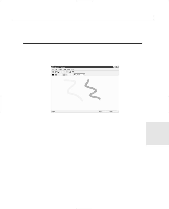
Adding Toolbars and Status Bars |
275 |
11:.
12:ON_COMMAND(ID_WIDTH_VTHIN, OnWidthVthin)
13://}}AFX_MSG_MAP
14:END_MESSAGE_MAP()
After adding the message handler and message map entry, you should now be able to compile and run your application and see the color status bar pane automatically updated to reflect the current drawing color, as shown in Figure 12.6.
FIGURE 12.6.
The drawing application with the current color displayed in the status bar.
Summary
You learned quite a bit today. (Is this becoming a trend?) You learned how to design and |
12 |
|
create your own toolbars. Along with learning how to design toolbars, you learned how |
||
|
||
to specify status bar prompts for the toolbar buttons and menus, along with tooltips text |
|
|
that will display after holding the mouse over toolbar buttons for a couple of seconds. |
|
|
You learned how to create these toolbars and how to attach them to the application |
|
|
frame. You also learned how you can control whether the toolbar is visible from a menu |
|
|
entry. |
|
|
Next you learned how to place a combo box on a toolbar so that you can provide your |
|
|
application users with the same level of convenience that you have when using many |
|
|
popular software packages. In learning how to add this combo box to the toolbar, you |
|
|
learned how to create a combo box in code, without having to depend on the dialog |
|
|
designers to create combo boxes, and how to populate the combo box drop-down list |
|
|
with text entries. Then, you learned how to tie the combo box into your application by |
|

276 |
Day 12 |
adding event handlers for the combo box events and how to update the combo box to reflect changes made through the application menus.
Finally, you learned how to add your own panes to the status bar and how you can update the pane to reflect the current status of the application.
Q&A
QIn some applications, toolbars have the option of showing text, as in Internet Explorer. How can I add text to my toolbar buttons?
AUnfortunately, the toolbar designer provides no way to add text to the toolbar buttons. This means that you have to add the text to the buttons in your application code, much in the same way that you had to specify for all of the color toolbar buttons to behave as radio buttons. You use the SetButtonText function to set the text on each toolbar button individually. This function takes two arguments: The first is the index number of the button, and the second is the text for the button. If you really want to place text on the toolbar buttons, you also have to resize the toolbar to allow the room for the text to be displayed.
QI made some changes to the color toolbar in the toolbar designer, and now I get an assertion error every time I try to run my application. What happened?
AThe problem is that the toolbar designer found the separators you added to the resource file as place holders for the combo box. The toolbar designer assumed that these were mistakes and removed them for you. The error that you are getting occurs because you are trying to work with a control in the color toolbar that doesn’t exist. To fix this problem, reopen the resource file in Notepad and again add the two separators at the end of the color toolbar definition. Then, reload the project into Visual C++ and recompile the application.
QThe combo box on my toolbars looks too big. How can I get it to fit within the toolbar a little better?
ATo make the combo box fit within the toolbar like the combo boxes in the Visual C++ Developer Studio, you need to do a couple of things. First, lower the top of the combo box by 3; this places a small border between the top of the combo box and the edge of the toolbar. Next, set the font in the combo box to a smaller font that will fit within the toolbar better. You can experiment with fonts and pitches until you have a font that you like for the combo box in the toolbar.
Adding Toolbars and Status Bars |
277 |
QHow can I set the text in the first section of the status bar other than by using menu and toolbar prompts?
AYou can use SetWindowText to set the text in the first pane of the status bar. As a default setting, the first pane in the status bar is a separator that automatically expands to fill the width of the status bar with the other panes right-justified on the bar. The SetWindowText function, called on the status bar variable, sets the text in the first pane only. If you want to set the text in any other pane, at any other time than in the ON_UPDATE_COMMAND_UI event handler, you can use the SetPaneText function. There are two ways that you can set the text in the main part of the status bar. The first is like this:
CString myString = “This is my string” m_wndStatusBar.SetWindowText(myString);
The other method is
CString myString = “This is my string” m_wndStatusBar.SetPaneText(0, myString);
Workshop
The Workshop provides quiz questions to help you solidify your understanding of the material covered and exercises to provide you with experience in using what you’ve learned. The answers to the quiz questions and exercises are provided in Appendix B, “Answers.”
Quiz |
12 |
1.How do you tie a toolbar button to a menu entry that triggers that same function?
2.How do you make sure that a toolbar can be docked with the frame window?
3.How can you remove the Num Lock status indicator from the status bar?
4.Why do you have to edit the resource file to add a combo box to a toolbar?
Exercises
1.Add another pane to the status bar to display the current width selected.
2.Add a button to the main toolbar that can be used to toggle the color toolbar on and off, as in Figure 12.7.
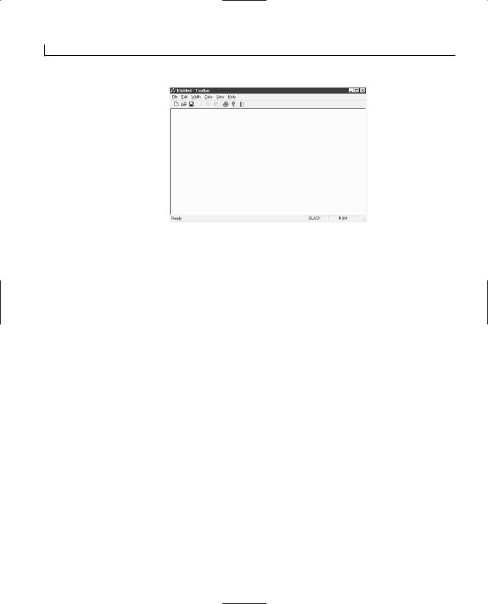
278 |
Day 12 |
FIGURE 12.7.
The color toolbar on/off button.

WEEK 2
DAY 13
Saving and Restoring
Work—File Access
Most applications provide the user the option of saving what has been created. The creation can be a word-processing document, a spreadsheet, a drawing, or a set of data records. Today, you will explore how Visual C++ provides you with the means to implement this functionality easily. Today, you will learn
●How Visual C++ uses C++ streams to save information about your application
●How to store your application data in binary files
●How to make your application objects serializable
●How you can store variables of differing data types into a single file
Serialization
There are two parts of serialization. When application data is stored on the system drive in the form of a file, it is called serialization. When the application

280 |
Day 13 |
state is restored from the file, it is called deserialization. The combination of these two parts makes up the serialization of application objects in Visual C++.
The CArchive and CFile Classes
Serialization in Visual C++ applications is accomplished through the CArchive class. The CArchive class is designed to act as an input/output (I/O) stream for a CFile object, as shown in Figure 13.1. It uses C++ streams to enable efficient data flow to and from the file that is the storage of the application data. The CArchive class cannot exist without a CFile class object to which it is attached.
FIGURE 13.1.
The CArchive class stores application data in a CFile object.
Application
Object
Serialize
Function
CArchive
CFile
The CArchive class can store data in a number of types of files, all of which are descendants of the CFile class. By default, the AppWizard includes all the functionality to create and open regular CFile objects for use with CArchive. If you want or need to work with one of these other file types, you might need to add additional code to your application to enable the use of these different file types.
Saving and Restoring Work—File Access |
281 |
The Serialize Function
The CArchive class is used in the Serialize function on the document and data objects in Visual C++ applications. When an application is reading or writing a file, the document object’s Serialize function is called, passing the CArchive object that is used to write to or read from the file. In the Serialize function, the typical logic to follow is to determine whether the archive is being written to or read from by calling the CArchive IsStoring or IsLoading functions. The return value from either of these two functions determines if your application needs to be writing to or reading from the CArchive class’s I/O stream. A typical Serialize function in the view class looks like Listing 13.1.
LISTING 13.1. A TYPICAL Serialize FUNCTION. |
|
||
|
1: void CAppDoc::Serialize(CArchive& ar) |
|
|
2: { |
|
|
|
3: |
// Is the archive being written to? |
|
|
4: |
if (ar.IsStoring()) |
|
|
5: |
{ |
|
|
6: |
// Yes, write my variable |
|
|
7: |
ar << m_MyVar; |
|
|
8: |
} |
|
|
9: |
else |
|
|
10: |
{ |
|
|
11: |
// No, read my variable |
|
|
12: |
ar >> m_MyVar; |
|
|
13: |
} |
|
|
14: } |
|
|
|
|
|
|
|
|
You can place a Serialize function in any classes you create so that you can call their |
|
|
|
Serialize function from the document Serialize function. If you place your custom objects |
|
|
|
into an object array, such as the CObArray that you used in your drawing application for |
|
|
|
the past three days, you can call the array’s Serialize function from the document’s |
|
|
|
Serialize function. The object array will, in turn, call the Serialize function of any objects |
13 |
|
|
that have been stored in the array. |
||
Making Objects Serializable
When you created the CLine class on Day 10, “Creating Single Document Interface Applications,” you had to add two macros before you could save and restore your drawings. These two macros, DECLARE_SERIAL and IMPLEMENT_SERIAL, include functionality in your classes that are necessary for the Serialize function to work correctly.
282 |
Day 13 |
Including the DECLARE_SERIAL Macro
You must include the DECLARE_SERIAL macro in your class declaration, as shown in Listing 13.2. The DECLARE_SERIAL macro takes a single argument, the class name. This macro automatically adds to your class some standard function and operator declarations that are necessary for serialization to work correctly.
LISTING 13.2. INCLUDING THE DECLARE_SERIAL MACRO IN THE CLASS DECLARATION.
1:class CMyClass : public CObject
2:{
3:DECLARE_SERIAL (CMyClass)
4:public:
5:virtual void Serialize(CArchive &ar);
6:CMyClass();
7:virtual ~CMyClass();
8:};
Including the IMPLEMENT_SERIAL Macro
You need to add the IMPLEMENT_SERIAL macro to the implementation of your class. This macro needs to appear outside any other class functions because it adds the code for the class functions that were declared with the macro.
The IMPLEMENT_SERIAL macro takes three arguments. The first argument is the class name, as in the DECLARE_SERIAL macro. The second argument is the name of the base class, from which your class is inherited. The third argument is a version number that can be used to determine whether a file is the correct version for reading into your application. The version number, which must be a positive number, should be incremented each time the serialization method of the class is changed in any way that alters the data being written to or read from a file. A typical usage of the IMPLEMENT_SERIAL macro is provided in Listing 13.3.
LISTING 13.3. INCLUDING THE IMPLEMENT_SERIAL MACRO IN THE CLASS IMPLEMENTATION.
1:// MyClass.cpp: implementation of the CMyClass class.
2://
3://////////////////////////////////////////////////////////////////////
5:#include “stdafx.h”
6:#include “MyClass.h”
8:#ifdef _DEBUG
9:#undef THIS_FILE
10: static char THIS_FILE[]=__FILE__;

Saving and Restoring Work—File Access |
283 |
11:#define new DEBUG_NEW
12:#endif
13:
14:IMPLEMENT_SERIAL (CMyClass, CObject, 1)
15://////////////////////////////////////////////////////////////////////
16:// Construction/Destruction
17://////////////////////////////////////////////////////////////////////
19:CMyClass::CMyClass()
20:{
21:}
23:CMyClass::~CMyClass()
24:{
25:}
Defining the Serialize Function
Along with the two macros, you need to include a Serialize function in your class. This function should be declared as a void function with a single argument (CArchive &ar), public access, and the virtual check box selected—producing the function declaration in Listing 13.2. When you implement the Serialize function for your class, you typically use the same approach as that used in the document class, shown in Listing 13.1, where you check to determine whether the file is being written to or read from.
Implementing a Serializable Class
When you begin designing a new application, one of the first things you need to design |
|
is how to store the data in the document class that your application will create and oper- |
|
ate on. If you are creating a data-oriented application that collects sets of data from the |
|
user, much like a contact database application, how are you going to hold that data in the |
|
application memory? What if you are building a word processor application—how are |
|
you going to hold the document being written in the application memory? Or a spread- |
13 |
sheet? Or a painting program? Or…you get the idea. |
Once you determine how you are going to design the data structures on which your application will operate, then you can determine how best to serialize your application and classes. If you are going to hold all data directly in the document class, all you need to worry about is writing the data to and reading the data from the CArchive object in the document’s Serialize function. If you are going to create your own class to hold your application data, you need to add the serialization functionality to your data classes so that they can save and restore themselves.
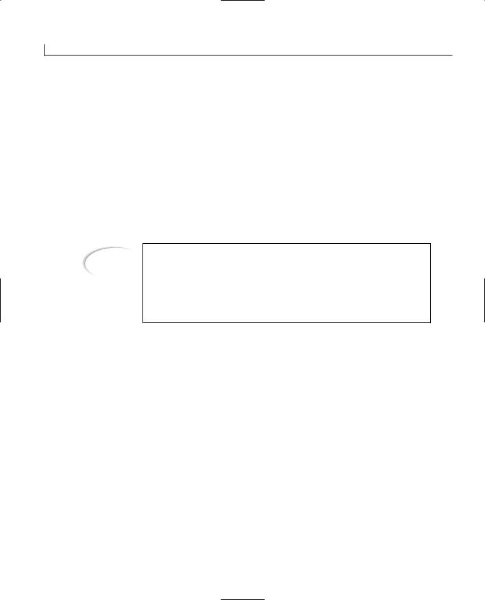
284 |
Day 13 |
In the application that you are going to build today, you will create a simple, flat-file database application that illustrates how you can combine a mixture of data types into a single data stream in the application serialization. Your application will display a few fields of data, some of which are variable-length strings, and others that are integer or boolean, and will save and restore them in a single data stream to and from the CArchive object.
Creating a Serialized Application
You can create your own classes, which can also be serialized, for use in an SDI or MDI application. In short, any application that works with any sort of data, whether a database or a document, can be serialized. Now you will create a simple, flat-file database application that you will serialize.
Note
A flat-file database is one of the original types of databases. It is a simple file-based database, with the records sequentially appended to the end of the previous record. It has none of the fancy relational functionality that is standard in most databases today. The database that you will build today is closer to an old dBASE or Paradox database, without any indexes, than to databases such as Access or SQL Server.
Creating the Application Shell
To get your application started, create a new AppWizard application. Give your application a name, such as Serialize, and click OK to start the AppWizard.
In the AppWizard, select to create a single document style application using the Document/View architecture. You can choose to include support for ActiveX controls in the third AppWizard step, although it’s not really necessary for the example that you will build.
In the fourth step, be sure to specify the file extension for the files that your application will create and read. An example of a file extension that you might want to use is ser for serialize or fdb for flat-file database.
In the sixth AppWizard step, you need to specify which base class to use for the application view class. For a description of the different base classes available for inheriting the view class from, refer to Day 10 in the section “The Document/View Architecture.” For the sample application you are building, because it will be a database application, you’ll
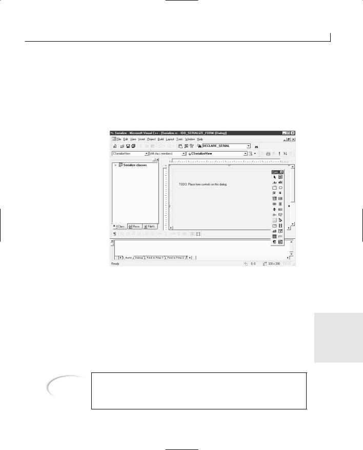
Saving and Restoring Work—File Access |
285 |
find it easiest to use CFormView as the base class from which your view class will be inherited. This enables you to use the dialog designer for your application view.
Once you finish making your way through the AppWizard and let the AppWizard create your application shell, you will see a large window canvas in the dialog designer as if you had created a dialog-style application, only without the OK and Cancel buttons, as shown in Figure 13.2.
FIGURE 13.2.
The window designer for an SDI application.
Designing Your Application Window
After you create an SDI or MDI application where the view class is based on the CFormView class, you need to design your application view. Designing the view is much like designing the window layout for a dialog window, but you don’t need to worry about including any buttons to close the window while either saving or canceling the work
done by the user. With an SDI or MDI application, the functionality to save and exit the 13 window is traditionally located on the application menus or on the toolbar. As a result,
you need to include only the controls for the function that your application window will perform.
Note
If you are building dialog-style applications, the AppWizard doesn’t provide any serialization code in your application shell. If you need to serialize a dialog-style application, you’ll need to add all this code yourself.
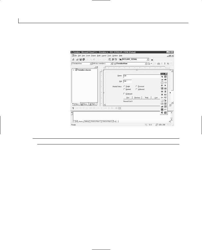
286 |
Day 13 |
For the sample application that you are building today, lay out controls on the window canvas as shown in Figure 13.3 using the control properties listed in Table 13.1.
FIGURE 13.3.
The sample application window layout.
TABLE 13.1. CONTROL PROPERTY SETTINGS.
Object |
Property |
Setting |
Static Text
Edit Box
Static Text
Edit Box
Static Text
Radio Button
Radio Button
Radio Button
ID |
IDC_STATIC |
Caption |
&Name: |
ID |
IDC_ENAME |
ID |
IDC_STATIC |
Caption |
&Age |
ID |
IDC_EAGE |
ID |
IDC_STATIC |
Caption |
Marital Status: |
ID |
IDC_RSINGLE |
Caption |
&Single |
Group |
Checked |
ID |
IDC_RMARRIED |
Caption |
&Married |
ID |
IDC_RDIVORCED |
Caption |
&Divorced |

Saving and Restoring Work—File Access |
287 |
Object |
Property |
Setting |
Radio Button
Check Box
Button
Button
Button
Button
Static Text
ID |
IDC_RWIDOW |
Caption |
&Widowed |
ID |
IDC_CBEMPLOYED |
Caption |
&Employed |
ID |
IDC_BFIRST |
Caption |
&First |
ID |
IDC_BPREV |
Caption |
&Previous |
ID |
IDC_BNEXT |
Caption |
Nex&t |
ID |
IDC_BLAST |
Caption |
&Last |
ID |
IDC_SPOSITION |
Caption |
Record 0 of 0 |
When you were developing dialog-style applications or windows, you attached variables to the controls on the window in the dialog class. However, with an SDI or MDI application, which class do you create the variables in? Because the UpdateData function is a member of the CWnd class, and the view class is descended from the CWnd class, although the document is not, then the view class is the most logical place to add the variables that you will attach to the controls you placed on the window.
To attach variables to the controls in your sample application, open the Class Wizard and add variables to the controls, specifying that the place to add them is the view class (in this case, CSerializeView). For the sample application, add the variables in Table 13.2 to the controls specified.
13
TABLE 13.2. CONTROL VARIABLES.
Object |
Name |
Category |
Type |
IDC_CBEMPLOYED |
m_bEmployed |
Value |
BOOL |
IDC_EAGE |
m_iAge |
Value |
int |
IDC_ENAME |
m_sName |
Value |
CString |
IDC_RSINGLE |
m_iMaritalStatus |
Value |
int |
IDC_SPOSITION |
m_sPosition |
Value |
CString |
|
|
|
|

288 |
Day 13 |
If you examine the source code for the view class, you will notice that there is no OnDraw function. If you are using the CFormView ancestor class for your SDI or MDI application, you don’t need to worry about the OnDraw function. Instead, you treat the view class very much as you would the dialog class in a dialog window or dialog-style application. The primary difference is that the data that you need to use to populate the controls on the window are not in the view class, but in the document class. As a result, you need to build the interaction between these two classes to pass the data for the controls back and forth.
Creating a Serializable Class
When you create a form-based application, it is assumed that your application will hold multiple records in the form and that the user will be able to scroll through the records to make changes. The user will be able to add additional records or even remove records from the record set. The challenge at this point in building this application is how you represent this set of records, supporting all the necessary functionality.
One approach is to create a class that would encapsulate each record, and then hold these records in an array, much as you did with the drawing application that you created and enhanced over the past few days. This class would need to descend from the CObject class and would need to contain variables for all the control variables that you added to the view class, along with methods to read and write all of these variables. Along with adding the methods to set and read all of the variables, you need to make the class serializable by adding the Serialize function to the class, as well as the two macros that complete the serialization of the class.
Creating the Basic Class
As you may remember from Day 10, when you want to create a new class, you can select the project in the Class View tab of the workspace pane, right-click the mouse button, and select New Class from the context menu. This opens the New Class dialog.
In the New Class dialog, you specify the type of class, whether it’s an MFC class, and generic class, or a form class. To create a class that can contain one record’s data, you most likely want to create a generic class. You’ll learn more about how to determine which of these types of classes to create on Day 16, “Creating Your Own Classes and Modules.” The other things that you need to do are give your class a name and specify the base class from which it will be inherited.
For your sample application, because the form that you created has information about a person, you might want to call your class something like CPerson. To be able to hold your class in the object array, you need to give it CObject as the base class. Just like on
Saving and Restoring Work—File Access |
289 |
Day 10, the New Class dialog will claim that it cannot find the header with the base class in it and that you need to add this. Well, it’s already included, so you can ignore this message. (On Day 16, you’ll learn when you need to pay attention to this message.)
Once you create your new class, you’ll need to add the variables for holding the data elements that will be displayed on the screen for the user. Following good object-oriented design, these variables will all be declared as private variables, where they cannot be directly manipulated by other classes. The variable types should match the variable types of the variables that are attached to the window controls in the view class.
With the sample application you are creating, you need to add the variables in Table 13.3.
TABLE 13.3. CLASS VARIABLES FOR THE CPerson CLASS.
Name |
Type |
m_bEmployed |
BOOL |
m_iAge |
int |
m_sName |
CString |
m_iMaritalStatus |
int |
|
|
Adding Methods for Reading and Writing Variables
Once you create your class, you need to provide a means for reading and writing to the variables in the class. One of the easiest ways to provide this functionality is to add inline functions to the class definition. You create a set of inline functions to set each of the variables and then make another set for retrieving the current value of each variable.
Note |
An inline function is a short C++ function in which, when the application is |
|
|
|
|||
being compiled, the function body is copied in place of the function call. As |
|
13 |
|
|
|
||
|
a result, when the compiled application is running, the function code is exe- |
|
|
|
cuted without having to make a context jump to the function and then |
|
|
|
jump back once the function has completed. This reduces the overhead in |
|
|
|
the running application, increasing the execution speed slightly, but also |
|
|
|
makes the resulting executable application slightly larger. The more places |
|
|
|
the inline function is called, the larger the application will eventually get. |
|
|
|
For more information on inline functions, consult Appendix A, “C++ |
|
|
|
Review.” |
|
|
|
|
|
|
290 |
Day 13 |
If you want to implement the Get and Set variable functions for your CPerson class in the sample application that you are building, edit the Person.h header file, adding the lines in Listing 13.4.
LISTING 13.4. THE Get AND Set INLINE FUNCTION DECLARATIONS.
1:class CPerson : public CObject
2:{
3:public:
4:// Functions for setting the variables
5:void SetEmployed(BOOL bEmployed) { m_bEmployed = bEmployed;}
6:void SetMaritalStat(int iStat) { m_iMaritalStatus = iStat;}
7:void SetAge(int iAge) { m_iAge = iAge;}
8:void SetName(CString sName) { m_sName = sName;}
9:// Functions for getting the current settings of the variables
10:BOOL GetEmployed() { return m_bEmployed;}
11:int GetMaritalStatus() { return m_iMaritalStatus;}
12:int GetAge() {return m_iAge;}
13:CString GetName() {return m_sName;}
14:CPerson();
15:virtual ~CPerson();
16:
17:private:
18:BOOL m_bEmployed;
19:int m_iMaritalStatus;
20:int m_iAge;
21:CString m_sName;
22:};
After you have the methods for setting and retrieving the values of the variables in your custom class, you’ll probably want to make sure that the variables are initialized when the class is first created. You can do this in the class constructor by setting each of the variables to a default value. For instance, in your sample application, you add the code in Listing 13.5 to the constructor of the CPerson class.
LISTING 13.5. THE CPerson CONSTRUCTOR.
1:CPerson::CPerson()
2:{
3:// Initialize the class variables
4:m_iMaritalStatus = 0;
5:m_iAge = 0;
6:m_bEmployed = FALSE;
7:m_sName = “”;
8:}
Saving and Restoring Work—File Access |
291 |
Serializing the Class
After you have your custom class with all variables defined and initialized, you need to make the class serializable. Making your class serializable involves three steps. The first step is adding the Serialize function to the class. This function writes the variable values to, and reads them back from, the CArchive object using C++ streams. The other two steps consist of adding the DECLARE_SERIAL and IMPLEMENT_SERIAL macros. Once you add these elements, your custom class will be serializable and ready for your application.
To add the Serialize function to your custom class, add a member function through the Class View tab in the workspace pane. Specify the function type as void, the function declaration as Serialize(CArchive &ar), and the access as public and check the Virtual check box. This should add the Serialize function and place you in the editor, ready to flesh out the function code.
In the Serialize function, the first thing you want to do is to call the ancestor’s Serialize function. When you call the ancestor’s function first, any foundation information that has been saved is restored first, providing the necessary support for your class before the variables in your class are restored. Once you call the ancestor function, you need to determine whether you need to read or write the class variables. You can do this by calling CArchive’s IsStoring method. This function returns TRUE if the archive is being written to and FALSE if it’s being read from. If the IsStoring function returns TRUE, you can use C++ I/O streams to write all your class variables to the archive. If the function returns FALSE, you can use C++ streams to read from the archive. In both cases, you must be certain to order the variables in the same order for both reading and writing. If you need more information about C++ streams, see Appendix A.
An example of a typical Serialize function for your sample custom class is shown in Listing 13.6. Notice that the CPerson variables are in the same order when writing to and reading from the archive.
LISTING 13.6. THE CPerson.Serialize FUNCTION. |
13 |
|
1:void CPerson::Serialize(CArchive &ar)
2:{
3:// Call the ancestor function
4:CObject::Serialize(ar);
5:
6:// Are we writing?
7:if (ar.IsStoring())
8:// Write all of the variables, in order
9:ar << m_sName << m_iAge << m_iMaritalStatus << m_bEmployed;
10:else
11:// Read all of the variables, in order
12:ar >> m_sName >> m_iAge >> m_iMaritalStatus >> m_bEmployed;
13:}


Saving and Restoring Work—File Access |
295 |
The other thing that you need to do to the document class to provide support for the record objects is make sure that the document knows about and understands the record object that it will be holding. You do this by including the custom class header file before the header file for the document class is included in the document class source code file. Because the document class needs to trigger actions in the view class, it’s a good idea to also include the header file for the view class in the document class.
To include these header files in your sample application, open the source-code file for the document class and add the two #include statements as shown in Listing 13.9.
LISTING 13.9. INCLUDING THE CUSTOM AND VIEW CLASSES IN THE DOCUMENT CLASS
IMPLEMENTATION.
1:// SerializeDoc.cpp : implementation of the CSerializeDoc class
2://
3:
4:#include “stdafx.h”
5:#include “Serialize.h”
7:#include “Person.h”
8:#include “SerializeDoc.h”
9:#include “SerializeView.h”
10:
11:#ifdef _DEBUG
12:#define new DEBUG_NEW
13:#undef THIS_FILE
14:static char THIS_FILE[] = __FILE__;
15:#endif
16:
17://////////////////////////////////////////////////////////////////////
18:// CSerializeDoc
Adding New Records |
|
|
|
||
Before you can navigate the record set, you need to be able to add new records to the |
13 |
|
object array. If you add a private function for adding new records, you can add new |
||
|
||
records to the set dynamically as new records are needed. Because new records should be |
|
|
presenting the user with blank or empty data fields, you don’t need to set any of the |
|
|
record variables when adding a new record to the object array, so you can use the default |
|
|
constructor. |
|
|
Following the same logic that you used to add new line records on Day 10, you should |
|
|
add a new person record to the object array in your document class in today’s sample |
|

Saving and Restoring Work—File Access |
297 |
25:pPerson = NULL;
26:}
27:// Delete the exception object
28:perr->Delete();
29:}
30:return pPerson;
31:}
Getting the Current Position
To aid the user in navigating the record set, it’s always helpful to provide a guide about where the user is in the record set. To provide this information, you need to be able to get the current record number and the total number of records from the document to display for the user.
The functions to provide this information are both fairly simple. For the total number of records in the object array, all you need to do is get the size of the array and return that to the caller.
For your sample application, add a new member function to the document class. Specify the function type as int, the function name as GetTotalRecords, and the access as public. Once you add the function, edit it using the code in Listing 13.11.
LISTING 13.11. THE CSerializeDoc.GetTotalRecords FUNCTION.
1:int CSerializeDoc::GetTotalRecords()
2:{
3:// Return the array count
4:return m_oaPeople.GetSize();
5:}
Getting the current record number is almost just as simple. If you are maintaining a position counter in the document class, this variable contains the record number that the user
is currently editing. As a result, all you need to do is return the value of this variable to 13 the calling routine. Because the object array begins with position 0, you probably need to
add 1 to the current position before returning to display for the user.
To add this function to your sample application, add another new member function to the document class. Specify the type as int, the function name as GetCurRecordNbr, and the access as public. Edit the function using the code in Listing 13.12.

Saving and Restoring Work—File Access |
301 |
the current size of the array and set the current position marker to one less than the number of records in the array. This is actually the last record in the array because the first record in the array is record 0. Once you set the current position marker, you can return a pointer to the last record in the array.
To add this function to your sample application, add a new member function to the document class. Specify the function type as CPerson* (a pointer to the custom class), the function name as GetLastRecord, and the access as public. Edit the function, adding the code in Listing 13.17.
LISTING 13.17. THE CSerializeDoc.GetLastRecord FUNCTION.
1:CPerson * CSerializeDoc::GetLastRecord()
2:{
3:// Are there any records in the array?
4:if (m_oaPeople.GetSize() > 0)
5:{
6:// Move to the last position in the array
7:m_iCurPosition = (m_oaPeople.GetSize() - 1);
8:// Return the record in this position
9:return (CPerson*)m_oaPeople[m_iCurPosition];
10:}
11:else
12:// No records, return NULL
13:return NULL;
14:}
Serializing the Record Set
When filling in the Serialize functionality in the document class, there’s little to do other than pass the CArchive object to the object array’s Serialize function, just as you did on Day 10.
When reading data from the archive, the object array will query the CArchive object to
determine what object type it needs to create and how many it needs to create. The object 13 array will then create each object in the array and call its Serialize function, passing the
CArchive object to each in turn. This enables the objects in the object array to read their own variable values from the CArchive object in the same order that they were written.
When writing data to the file archive, the object array will call each object’s Serialize function in order, passing the CArchive object (just as when reading from the archive). This allows each object in the array to write its own variables into the archive as necessary.
For the sample application, edit the document class’s Serialize function to pass the


Saving and Restoring Work—File Access |
311 |
FIGURE 13.4.
The running serialization application.
At this point, you can add, edit, save, and restore sets of records with your application. If you compile and run your application, you can create records of yourself and all your family members, your friends, and anyone else you want to include in this application. If you save the record set you create and then reopen the record set the next time that you run your sample application, you should find that the records are restored back to the state that you originally entered them, as in Figure 13.4.
Summary
Today, you learned quite a bit. You learned how serialization works and what it does. You learned how to make a custom class serializable and why and how to use the two macros that are necessary to serialize a class. You also learned how to design and build a formbased SDI application, maintaining a set of records in a flat-file database for use in the application. You learned how to use serialization to create and maintain the flat-file database and how to construct the functionality in the document and view classes to provide navigating and editing capabilities on these record sets.
13
Q&A
QIf I make any changes to one of the records in my record set after I save the record set and then I close the application, or open a different set of records, my application doesn’t ask if I want to save my changes. How do I get it to ask me? How do I get my application to prompt for saving when data has been changed?

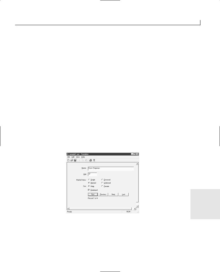
Saving and Restoring Work—File Access |
313 |
will have changed, and you do need to increment the version number. If you don’t increment the version number, reading files created using the previous version of your application will result in an “Unexpected file format” message instead of the file being read. Once you increment the version number and you read a file written with the old version number, you get the same message, but you have the option of writing your own code to handle the exception and redirecting the archive to a conversion routine to convert the file to the new file format.
Workshop
The Workshop provides quiz questions to help you solidify your understanding of the material covered and exercises to provide you with experience in using what you’ve learned. The answers to the quiz questions and exercises are provided in Appendix B, “Answers.”
Quiz
1.What two macros do you have to add to a class to make it serializable?
2.How can you determine whether the CArchive object is reading from or writing to the archive file?
3.What arguments do you need to pass to the IMPLEMENT_SERIAL macro?
FIGURE 13.5.
The running serialization application with the person’s sex.
13


WEEK 2
DAY 14
Retrieving Data from an ODBC Database
A large number of applications use a database. Everything from a personal organizer to a large, corporate personnel system uses a database to store and maintain all the records that the applications use and manipulate. Visual C++ provides you with four different technologies for using and accessing databases in your applications, Data Access Objects (DAO), ODBC, OLE DB, and ActiveX Data Objects (ADO). Today and tomorrow, you’ll learn about two of these technologies, how they differ, and how you can use them in your own applications. Today, you will learn
●How the ODBC interface allows you to use a consistent way to access a database.
●How Visual C++ uses the CRecordset class to provide access to an ODBC data source.
●How you can create a simple database application using the Wizards in Visual C++.
●How you can add and delete records from an ODBC database in Visual C++.


Retrieving Data from an ODBC Database |
319 |
Once the user finishes working with the record set, you can call the Close function to close the record set and free any resources used by the record set. The Close function doesn’t take any arguments.
Navigating the Record Set
Once you have a set of records retrieved from the database, you need to be able to navigate the set of records (unless the set has only one record). The CRecordset class provides several functions for navigating the record set, allowing you to move the user to any record. Table 14.3 lists the functions that you use to navigate the record set.
TABLE 14.3. RECORD SET NAVIGATION FUNCTIONS.
Function |
Description |
MoveFirst |
Moves to the first record in the set. |
MoveLast |
Moves to the last record in the set. |
MoveNext |
Moves to the next record in the set. |
MovePrev |
Moves to the previous record in the set. |
Move |
Can be used to move a specific number of records from the current record or |
|
from the first record in the set. |
SetAbsolutePosition |
Moves to the specified record in the set. |
IsBOF |
Returns TRUE if the current record is the first record in the set. |
IsEOF |
Returns TRUE if the current record is the last record in the set. |
GetRecordCount |
Returns the number of records in the set. |
|
|
Of all of these navigation and informational functions, only two, Move and SetAbsolutePosition, take any arguments. The SetAbsolutePosition function takes a single numeric argument to specify the row number of the record toward which to navigate. If you pass 0, it navigates to the beginning-of-file (BOF) position, whereas 1 takes you to the first record in the set. You can pass negative numbers to this function to cause it to count backward from the last record in the set. (For example, –1 takes you to the last record in the set, –2 to the next-to-last record, and so on.)
The Move function takes two arguments. The first argument is the number of rows to move. This can be a positive or negative number; a negative number indicates a back-
ward navigation through the record set. The second argument specifies how you will 14 move through the set of rows. The possible values for the second argument are listed in
Table 14.4 with descriptions of how they affect the navigation.

Retrieving Data from an ODBC Database |
321 |
record will be lost. Once you save the new record, you need to call the Requery function to refresh the record set so that you can navigate to the new record and let the user edit it. This sequence of function calls typically looks like the following:
//Add a new record to the record set m_pSet.AddNew();
//Set the key field on the new record m_pSet.m_AddressID = m_lNewID;
//Save the new record to the database m_pSet.Update();
//Refresh the record set
m_pSet.Requery();
// Move to the new record m_pSet.MoveLast();
When you need to delete the current record, you can simply call the Delete function. Once you delete the current record, you need to navigate to another record so the user isn’t still looking at the record that was just deleted. Once you delete the current record, there is no current record until you navigate to another one. You do not need to explicitly call the Update function because the navigation functions call it for you. This allows you to write the following code to delete the current record:
//Delete the current record m_pSet.Delete();
//Move to the previous record m_pSet.MovePrev();
Finally, to allow the user to edit the current record, you need to call the Edit function. This allows you to update the fields in the record with the new values entered by the user or calculated by your application. Once all changes are made to the current record, you need to call the Update function to save the changes:
//Allow the user to edit the current record m_pSet.Edit();
//Perform all data exchange, updating the fields in the recordset
.
.
//Save the user’s changes to the current record
m_pSet.Update();
You might be wondering how you get to the fields in the records to update them. When the AppWizard creates the CRecordset-derived class for your application, it adds all the fields in the records that will be in the record set as member variables in order of the
record set class. As a result, you can access the member variables in order to access and 14 manipulate the data elements in the database records that are members of the record set.
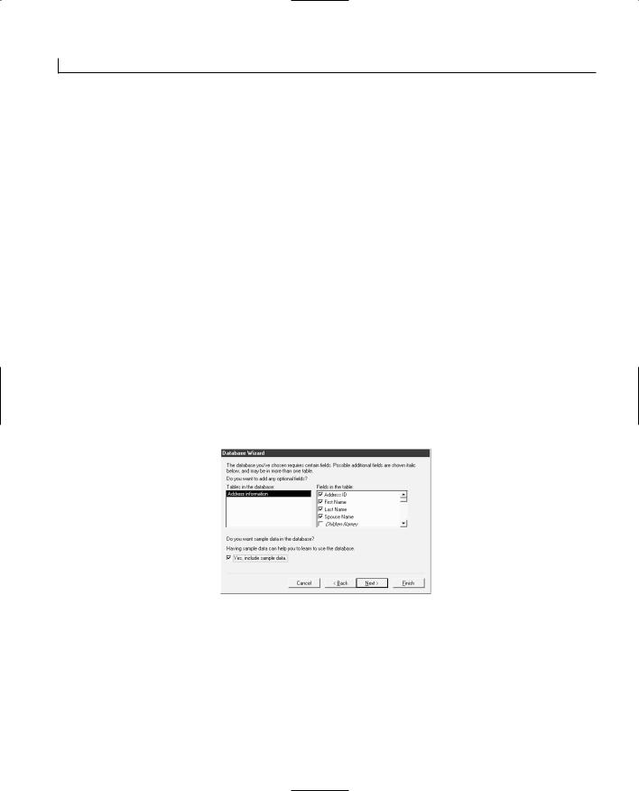
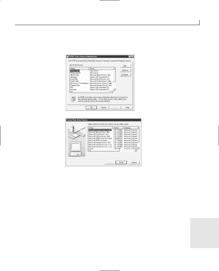
Retrieving Data from an ODBC Database |
323 |
For the sample application that you will build today, because the database was created using Access, select the Microsoft Access Driver and click the Finish button.
FIGURE 14.2.
The ODBC Data
Source Administrator.
FIGURE 14.3.
The Create New Data
Source dialog.
In the ODBC Microsoft Access Setup dialog, shown in Figure 14.4, you’ll provide a short, simple name for the data source. Your application will use this name to specify the ODBC data source configuration to use for the database connection, so it should reflect the function that the database will be serving, or it should be similar to the name of the application that will be using this database. For the purposes of the sample application database, name your data source TYVCDB (for Teach Yourself Visual C++ Database) and enter a description for the database in the next field.
Once you enter a name and description for the data source, you need to specify where |
|
the database is. Click the Select button and then specify the Access database that you |
14 |
created. Once you finish configuring the ODBC data source for your database, click the |
OK button to add the new data source to the ODBC Administrator. You can click the OK button to finish the task and close the ODBC Administrator because you are now ready to turn your attention to building your application.
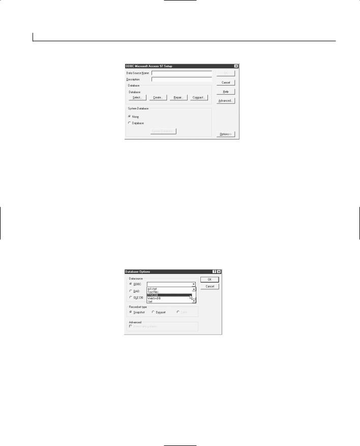
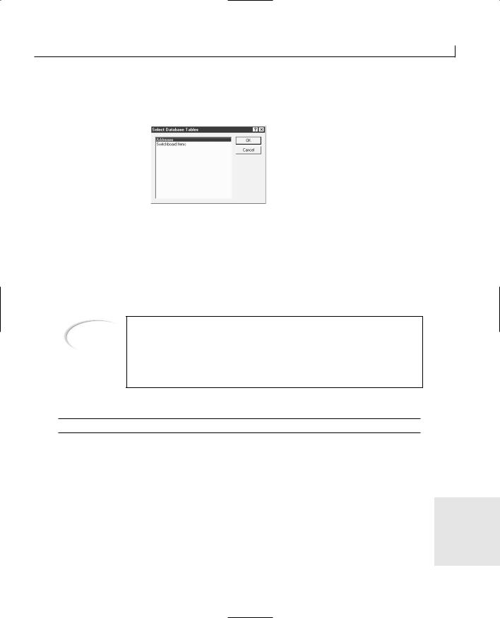

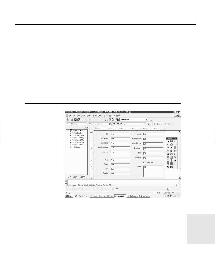
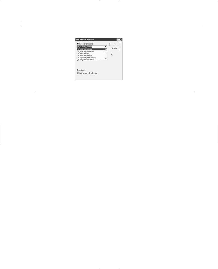
Retrieving Data from an ODBC Database |
329 |
data between a control and a CTime variable. This is also a problem because the CTime variable type cannot handle dates before December 31, 1969. To use this database field, you’ll need to change its definition from a CTime to a COleDateTime variable type, as in line 17 in Listing 14.1. Once you change the variable type of this database field, you will be able to attach it to the control.
LISTING 14.1. THE DATABASE FIELD VARIABLE DECLARATIONS.
1:// Field/Param Data
2://{{AFX_FIELD(CTestdb5Set, CRecordset)
3: |
long m_AddressID; |
|
4: |
CString |
m_FirstName; |
5: |
CString |
m_LastName; |
6: |
CString |
m_SpouseName; |
7: |
CString |
m_Address; |
8: |
CString |
m_City; |
9:CString m_StateOrProvince;
10:CString m_PostalCode;
11:CString m_Country;
12:CString m_EmailAddress;
13:CString m_HomePhone;
14:CString m_WorkPhone;
15:CString m_WorkExtension;
16:CString m_FaxNumber;
17:COleDateTime m_Birthdate;
18:BOOL m_SendCard;
19:CString m_Notes;
20://}}AFX_FIELD
Note |
Normally, you do not want to edit the portions of code in your applications |
|
that are created and maintained by the various wizards. The change I out- |
||
|
||
|
line here is one of the few exceptions to this rule. This obstacle could |
|
|
possibly be considered a bug in the Visual C++ AppWizard, although it’s |
|
|
technically not a bug. You can convert the date/time database field to sev- |
|
|
eral variable types when creating a class variable to represent that field. |
|
|
CTime is one of these variable types; COleDateTime is another. Because these |
|
|
are both equally valid choices, and the functions that populate this variable |
|
|
can work with either, making this change is possible without dire conse- |
|
|
quences. |
14
Once you make the change to the variable type for the m_Birthdate variable in the record set class (CDbOdbcSet), and attach this database field to the Birthdate control on the form, you might think that you are ready to compile and run your application. Unfortunately, your application will not compile. You’ll get a compiler error stating that

Retrieving Data from an ODBC Database |
331 |
initialization of this variable in the set class constructor, in line 19 of Listing 14.3.
LISTING 14.3. THE CDbOdbcSet CONSTRUCTOR. |
|
|
||
|
1: CDbOdbcSet::CDbOdbcSet(CDatabase* pdb) |
|
||
2: |
: CRecordset(pdb) |
|
||
3: { |
|
|
|
|
4: |
//{{AFX_FIELD_INIT(CTestdb5Set) |
|
||
5: |
m_AddressID = 0; |
|
||
6: |
m_FirstName = _T(“”); |
|
||
7: |
m_LastName = _T(“”); |
|
||
8: |
m_SpouseName = _T(“”); |
|
||
9: |
m_Address = _T(“”); |
|
||
10: |
m_City = _T(“”); |
|
||
11: |
m_StateOrProvince = _T(“”); |
|
||
12: |
m_PostalCode = _T(“”); |
|
||
13: |
m_Country = _T(“”); |
|
||
14: |
m_EmailAddress = _T(“”); |
|
||
15: |
m_HomePhone = _T(“”); |
|
||
16: |
m_WorkPhone = _T(“”); |
|
||
17: |
m_WorkExtension = _T(“”); |
|
||
18: |
m_FaxNumber = _T(“”); |
|
||
19: |
//m_Birthdate = 0; |
|
||
20: |
m_SendCard = FALSE; |
|
||
21: |
m_Notes = _T(“”); |
|
||
22: |
m_nFields = 17; |
|
||
23: |
//}}AFX_FIELD_INIT |
|
||
24: |
m_nDefaultType = dynaset; |
|
||
25: } |
|
|
|
|
|
|
|
|
|
|
Now compile and run your application once again. You’ll find that you have a fully func- |
|
||
|
tioning database application that retrieves a set of records from the database and allows |
|
||
|
you to scroll through them and make changes to the data, as shown in Figure 14.9. |
|
||
|
Adding New Records |
|
||
|
You’ve already created a fully functioning database application without writing a single |
|
||
|
line of code. However, a few functions are missing. Most database applications let the |
|
||
|
user add new records to the database. To add a new record to the database, you’ll want to |
|
||
|
figure out what the next ID number should be, so you’ll scroll to the last record in the set |
|
||
|
to get the ID and then increment it by one. Next, you’ll call the AddNew function to add a |
14 |
||
|
new record, set the ID field to the new ID you calculated, and then call the Update func- |
|||
|
tion to save the new record. Finally, you’ll call the Requery function to refresh the set of |
|
||
|
records and then scroll to the last record in the set to let the user enter data into the new |
|
||
|
record. |
|
|
|
|
|
|
|
|
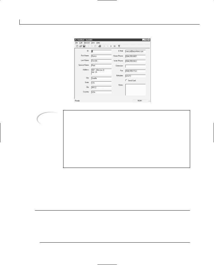


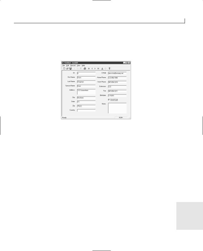
Retrieving Data from an ODBC Database |
335 |
Add another button to the toolbar and associate it with the IDM_RECORD_DELETE menu ID so that the user can delete the current record without having to go to the menu. If you compile and run your application at this point, you’ll have a full-function database application in which you can add, edit, and delete records, as shown in Figure 14.10.
FIGURE 14.10.
The completed application.
Summary
Today, you learned how you can use the ODBC interface to build database applications that can be easily run against any database you might need to use. You saw how the CRecordset class provides you with a substantial amount of functionality so that you can provide database functionality in your applications. You also saw how the AppWizard provides you with a large amount of database functionality without your typing a single line of code.
Tomorrow, you will learn about Microsoft’s newest database access technology, ActiveX Data Objects, and how this can be combined with the ODBC interface to make your database access even easier.
Q&A
QWhy would I want to use the ODBC interface instead of the Data Access Objects?
A The Data Access Objects (DAO) use the Microsoft Jet database engine to perform |
14 |
all of the database access. This adds at least a megabyte of overhead to your application, and if you’re using a SQL-based database, the database is already doing all of the work that the Jet engine is doing for you. What’s more, the Jet database


In Review |
339 |
with it in a seamless manner. You should be able to declare a variable for the control, set the control’s properties, call its methods, and react to its events just as if it were a standard part of the Visual C++ development environment. If you aren’t sure how you can do some of this, you might want to go back and reread Day 9.
Finally, you started this week by learning how to draw graphics on the windows of your applications. You learned how to draw lines, circles, and squares, using a variety of pens and brushes. You even learned how you can make a customized brush from a bitmap.
You learned how you can load a bitmap image from a file and display it for the user to see. But most importantly, you learned about the device context and how it is used to draw all these features on the windows of your applications. You should be able to use these and other figure drawing device context methods to draw any image you might want to draw on the window for the user to see and interact with. If you are unsure about how you can do this, you probably want to look back at Day 8 once more.
By this time, you have built up quite a set of programming skills with Visual C++. You are probably ready to tackle most of the smaller programming tasks you might encounter—and maybe even a few not-so-small tasks. At this point, you are well on your way to becoming an accomplished Visual C++ programmer. That said—now is not the time to stop because there’s still more to be learned. There’s only one more week to go, so tallyho!


WEEK 3
DAY 15
Updating and Adding
Database Records
Through ADO
Now that you’ve gotten your feet wet with an ODBC database application, one of the oldest Microsoft database access technologies, it’s time to turn your attention to the newest Microsoft database access technology, ActiveX Data Objects (ADO). Designed for use with all of Microsoft’s programming and scripting technologies, ADO presents the Visual C++ programmer with new challenges in database programming, while still keeping the functionality familiar. Today, you will learn
●How ADO works and how it uses the OLE DB technology for providing simple database access.
●How you can build a simple ADO application in a couple of minutes using ActiveX controls.

Updating and Adding Database Records Through ADO |
345 |
ADO Objects
To make ADO as easily usable in scripting languages such as VBScript as it is in pro- |
15 |
gramming environments such as Visual Basic, Microsoft tried to keep the number of objects to a minimum. As a result, you have a small number of basic objects:
●Connection
●Error
●Command
●Parameter
●Recordset
●Field
Along with these objects, you have collection objects for containing collections of Error,
Parameter, and Field objects.
The Connection Object
The Connection object is used for establishing and maintaining a connection to a database. This object is configured with the connection information, including database location, user ID, and password, before opening the connection. Once all of this information is appropriately configured, the connection object should have its Open method called to open the connection. Once the Connection object goes out of scope, the connection is automatically closed. If you want more control over closing and opening the database connection, you can call the Connection object’s Close method to close the connection.
The Connection object is also the object through which any high-level connection functionality is controlled. This includes all transaction control, through the Connection object’s BeginTrans, CommitTrans, and RollbackTrans methods.
The Error Object
Whenever a database error occurs, the error information from the database is placed into an ADO Error object. The error information in the error object is the database error information, not ADO error information. Whenever you encounter an error and need to look up the error information to determine what went wrong, you’ll need to examine the database error codes and descriptions, not the ADO error codes.
The Command Object
The Command object is used to execute commands in the database. You can use this object to run SQL statements or call stored procedures (SQL functions that are stored in

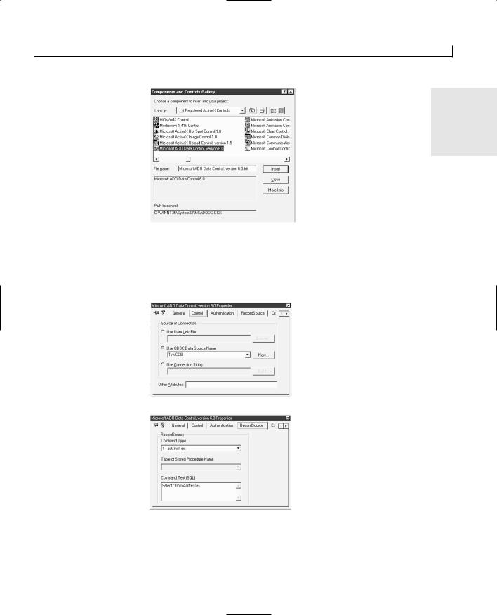
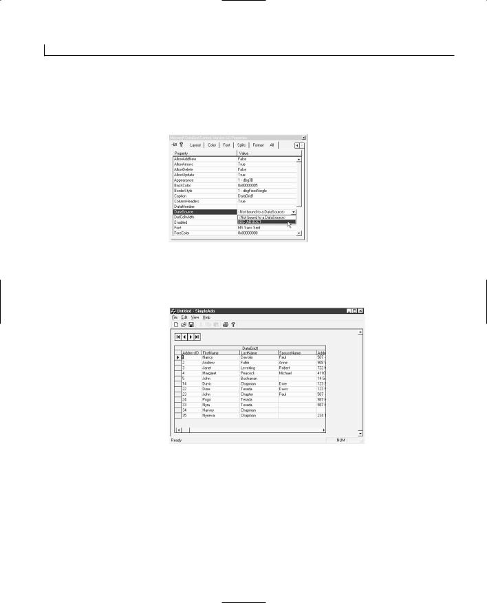

Updating and Adding Database Records Through ADO |
349 |
additional overhead on the application). Finally, not all data-bound controls are ADO |
|
|
enabled. ADO is such a new technology that there are few controls that you can use with |
15 |
|
it at this time. You may find some controls that allow you to retrieve and display data for |
||
|
||
the user, but do not allow the user to change and edit the data. Others may not even pro- |
|
|
vide you with that much functionality. |
|
|
Importing the ADO DLL |
|
|
|
||
If you look around in the MFC class hierarchy, you’ll find that there are no classes for |
|
|
use with ADO. If you don’t want to use the controls approach, then what are your |
|
|
options? Do you have to create the classes yourself? No, Microsoft has provided other |
|
|
means for you to create and use classes for each of the objects in ADO, through the use |
|
|
of a new C++ precompiler directive called #import. |
|
|
The #import precompiler directive was first added to Visual C++ with the 5.0 release. |
|
|
You can use this directive to import an ActiveX DLL that has been built with the |
|
|
IDispatch interface description included in the DLL. This directive tells the Visual C++ |
|
|
compiler to import the DLL specified by the #import directive and to extract the object |
|
|
information from the DLL, creating a couple of header files that are automatically |
|
|
included in your project. These header files have the filename extensions .TLH and .TLI |
|
|
and are in the output directory for your project (the Debug or Release directory, the same |
|
|
directory where you’ll find the executable application after you’ve compiled your pro- |
|
|
ject). These two files contain definitions of classes for each of the objects in the DLL |
|
|
that you can use in your code. The #import directive also tells the compiler to include the |
|
|
DLL as part of the project, eliminating the need to include the .LIB file for the DLL in |
|
|
your project. |
|
|
You can import the ADO DLL by placing the following code at the beginning of the |
|
|
header file in which you are defining any database objects: |
|
|
#define INITGUID |
|
|
#import “C:\Program Files\Common Files\System\ADO\msado15.dll” |
|
|
rename_namespace(“ADOCG”) rename(“EOF”, “EndOfFile”) |
|
|
using namespace ADOCG; |
|
|
#include “icrsint.h” |
|
|
In these four lines of directives, the first line defines a constant that needs to be defined |
|
|
for ADO. The second imports the ADO DLL, creating the two header files mentioned |
|
|
earlier. After the filename to be imported, this directive includes two attributes to the |
|
|
#import directive. The first, rename_namespace, renames the namespace into which |
|
|
the DLL has been imported. This is followed with the line following the #import, where |
|
|
the renamed namespace is specified as the one used. The second attribute, rename, |
|
|
renames an element in the header files that are created using the #import directive. |
|
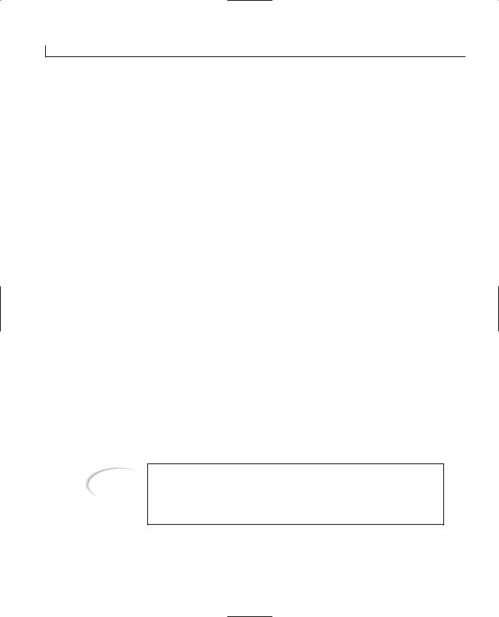
Updating and Adding Database Records Through ADO |
351 |
an ODBC OLE DB driver, where OLE DB is sitting on top of an ODBC data source, as
you’ll use in your sample application. If you are using SQL Server or Oracle databases, 15 it may be a direct connection to the OLE DB interface provided by the database itself.
The second parameter is the user ID for connecting to the database. The third parameter is the password for connecting to the database. The fourth parameter is the cursor type to use with the database. These types are defined in the msado15.tlh header file that is created by the #import directive. A typical use of the Open function to connect to an ODBC data source that doesn’t need a user ID or password is like the following:
pConn->Open(L”Provider=MSDASQL.1;Data Source=TYVCDB”, L””, L””,
adOpenUnspecified);
Executing Commands and Retrieving Data
Once you have the connection open, you can use a Command object to pass SQL commands to the database. This is the normal method of executing SQL commands with ADO. To create a Command object, follow the same process that you used to create a Connection object. Declare a Command object pointer, _CommandPtr, and then create an instance of it using the UUID of the Command object, as follows:
_CommandPtr pCmd; pCmd.CreateInstance(__uuidof(Command));
Once you create your Command object, assuming that you have already established the connection to the database, set the active connection property of the Command object to the open Connection object pointer, as follows:
pCmd->ActiveConnection = pConn;
Next, specify the SQL command to be executed by setting the CommandText property of the Command object, as follows:
pCmd->CommandText = “Select * from Addresses”;
At this point, you have two options for how you execute this command and retrieve the records. The first is to call the Command object’s Execute method, which will return a new Recordset object, which you’ll want to set to a Recordset object pointer, as follows:
_RecordsetPtr pRs;
pRs = pCmd->Execute();
The other approach to running the command and retrieving the records is to specify that the Command object is the source for the records in the Recordset. This requires creating the Recordset object as follows:
_RecordsetPtr pRs; pRs.CreateInstance(__uuidof(Recordset)); pRs->PutRefSource(pCmd);
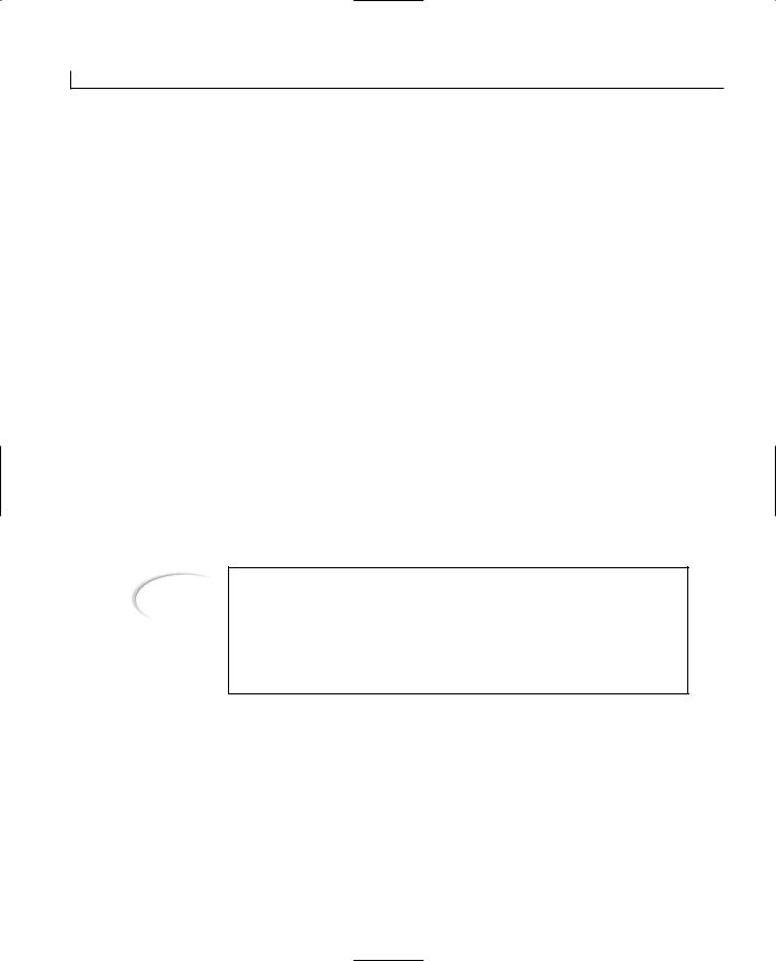

Updating and Adding Database Records Through ADO |
353 |
Along with these functions, the Recordset object also has two properties, BOF and EOF
(which you should normally rename to prevent a collision with the default definition of 15 EOF), which can be checked to determine if the current record in the set is beyond either
end of the set of records.
Accessing Field Values
When you need to begin accessing the data values in each of the fields is where working with ADO in Visual C++ begins to get interesting. Because ADO is intended to be easy to use in Microsoft’s scripting languages, VBScript and JScript, which only have
variant data types, all data elements that you’ll retrieve from fields in the ADO Recordset are variant values. They have to be converted into the data types that you need them to be. There are two ways of doing this. The first way is the straight-forward way of retrieving the values into a variant and then converting them, as in the following code:
_variant_t vFirstName; CString strFirstName;
vFirstName = pRs->GetCollect(_variant_t(“FirstName”)); vFirstName.ChangeType(VT_BSTR);
strFirstName = vFirstName.bstrVal;
The not-so-straight-forward way to do this is actually the better way, and in the long run, is a lot easier to work with. Microsoft has created a series of macros that perform the conversion for you and that maintain a set of variables of the records in the set. To do this, you’ll define a new class to use as the interface for your record set. This class will be a descendent of the CADORecordBinding class, which is defined in the icrsint.h header file, which you included just after the #import directive. This class will not have any constructor or destructor but will have a series of macros, along with a number of variables. Each field in the set of records has two variables, an unsigned long, which is used to maintain the status of the variable, and the field variable itself. These variables must be regular C variables, and they cannot be C++ classes such as CString. A simple example of this class declaration is the following:
class CCustomRs :
public CADORecordBinding
{
BEGIN_ADO_BINDING(CCustomRs)
ADO_FIXED_LENGTH_ENTRY(1, adInteger, m_lAddressID, lAddressIDStatus,FALSE)
ADO_VARIABLE_LENGTH_ENTRY2(2, adVarChar, m_szFirstName,sizeof(m_szFirstName), lFirstNameStatus, TRUE)
ADO_FIXED_LENGTH_ENTRY(3, adDate, m_dtBirthdate, lBirthdateStatus,TRUE)
ADO_FIXED_LENGTH_ENTRY(4, adBoolean, m_bSendCard, lSendCardStatus,TRUE)
END_ADO_BINDING()


Updating and Adding Database Records Through ADO |
355 |
size. It can be used with a date or boolean field, or even a text field that is a fixed size,
with no option for any variation in the database. There are two versions of this macro; 15 you add a 2 to the end of the name of the second version (ADO_FIXED_LENGTH_ENTRY2).
Both versions require the same first three and last parameters. The first version requires an additional parameter that is not required in the second version. The first parameter is the ordinal number of the field in the record set. This is the position in the field order as returned by the SQL query that is run to populate the record set. The second parameter is the data type of the field; the available data types are defined in the header file created by the #import directive. The third parameter is the variable into which the data value is to be copied. For the first version of the macro, the fourth parameter is the variable for the field status (the unsigned long that you defined with the variable for the actual value). The last variable is a boolean that specifies whether this field can be modified.
The ADO_NUMERIC_ENTRY Macros
You use the ADO_NUMERIC_ENTRY macros with numeric fields only. They are similar to the ADO_FIXED_LENGTH_ENTRY macros in that there are two different versions of the macro, named in the same way. In these macros, the first five parameters are the same in both versions, along with the final parameter. Like with the ADO_FIXED_LENGTH_ENTRY macros, the first version has an additional parameter that is not used in the second version.
The first three parameters for the ADO_NUMERIC_ENTRY macros are the same as those for the ADO_FIXED_LENGTH_ENTRY macros, as are the last parameter and the next to last parameter for the first version. It is the fourth and fifth parameters that are unique to these macros. The fourth parameter specifies the precision of the value in this field of the record set. The fifth parameter specifies the scale of the value. Both of these parameters are crucial in correctly converting the value to and from a variant data type.
The ADO_VARIABLE_LENGTH_ENTRY Macros
The final series of macros is the ADO_VARIABLE_LENGTH_ENTRY macros. You use this series of macros with database fields that are likely to vary in length. With a SQL-based database, you want to use this series of macros with any varchar (variable-length character string) columns. There are three versions of this macro. In all three versions, the first four parameters are the same, and the final parameter is the same. It is the parameters between them that vary.
The first parameter is the ordinal position of the column in the record set as returned by the SQL query. The second parameter is the data type. The third parameter is the variable


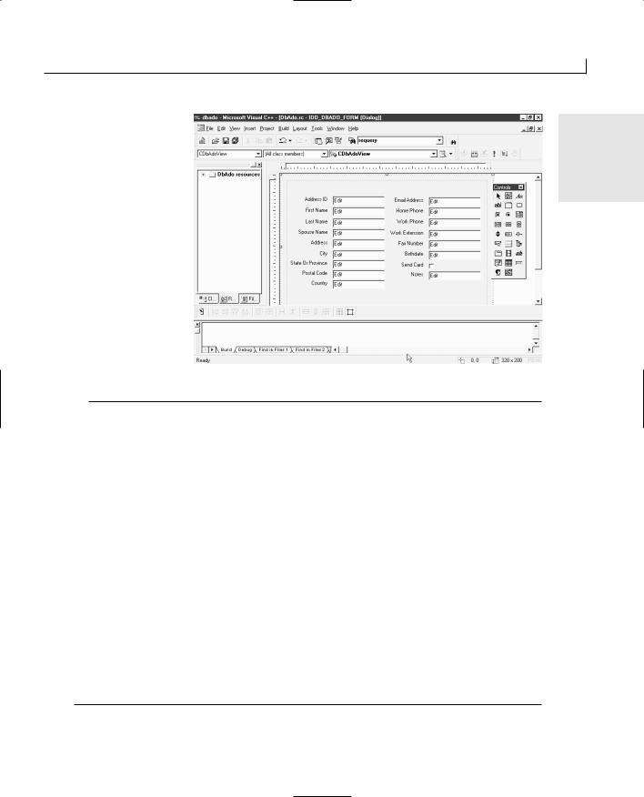


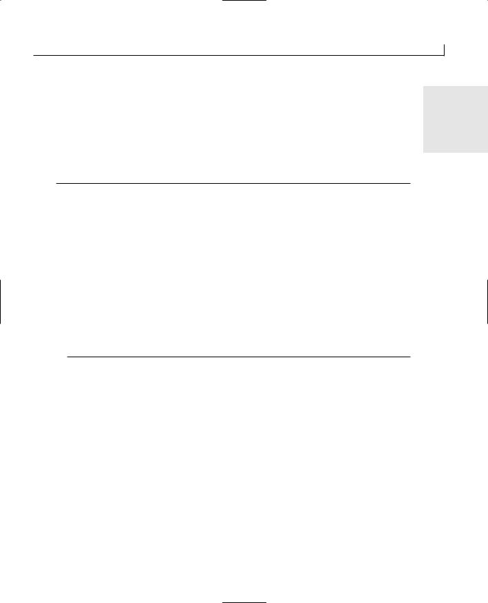
Updating and Adding Database Records Through ADO |
367 |
Before moving any further, it’s a good idea to make sure that you add all the code neces-
sary to clean up as your application is closing. You need to close the record set and 15 release the pointer to the record binding interface. You’ll also shut down the COM envi-
ronment. To add all this functionality to your application, add a function to the DeleteContents event message in the document class. Edit this function, adding the code in Listing 15.6.
LISTING 15.6. THE CDbAdoDoc DeleteContents FUNCTION.
1:void CDbAdoDoc::DeleteContents()
2:{
3:// TODO: Add your specialized code here and/or call the base class
4:// Close the record set
5:if (m_pRs)
6:m_pRs->Close();
7:// Do we have a valid pointer to the record binding?
8:if (m_piAdoRecordBinding)
9:// Release it
10:m_piAdoRecordBinding->Release();
11:// Set the record set pointer to NULL
12:m_pRs = NULL;
13:
14:// Shut down the COM environment
15:CoUninitialize();
16:
17:CDocument::DeleteContents();
18:}
Populating the Form
To display the record column values for the user, you’ll add a function for copying the values from the record class to the view variables. This function first needs to get a pointer to the record class from the document class. Next, it will check the status of each individual field in the record class to make sure that it’s okay to copy, and then it will copy the value. Once all values have been copied, you can call UpdateData to display the values in the controls on the form. To add this functionality to your application, add a new member function to the view class. Specify the function type as void, the function declaration as RefreshBoundData, and the access as public. Edit this new function, adding the code in Listing 15.7.

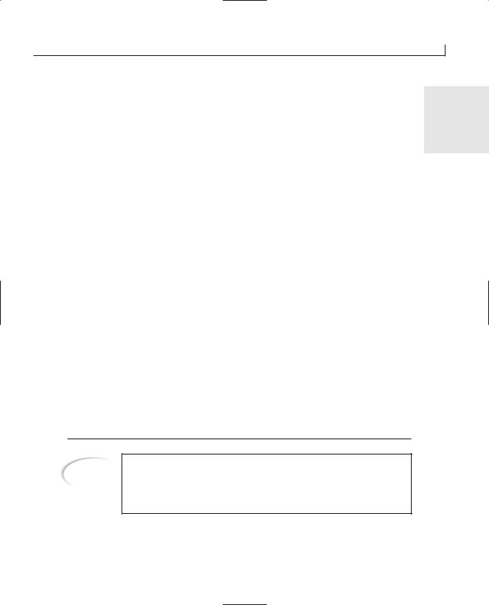


Updating and Adding Database Records Through ADO |
373 |
FIGURE 15.7.
The running |
15 |
|
|
application. |
|
Adding New Records
Now that you are able to retrieve and navigate the set of records in the database table, it would be nice if you could add some new records to the table. You can add this functionality in exactly the same fashion that you added the navigation functionality. Add a menu, trigger an event function in the view class from the menu, update the current record values back to the record set, call a function in the document class, and refresh the current record from the record set. As far as the menu and the view class are concerned, the only difference between this functionality and any of the navigation menus and functions is the ID of the menu and the name of the functions that are called, just as with the different navigation functions. It’s in the document function where things begin to diverge just a little.
In the document class function for adding a new record, once you’ve updated the current record, you’ll make sure that adding a new record is an option. If it is, then you’ll build an empty record and add it to the record set. Once you’ve added the empty record, navigate to the last record in the set because this will be the new record. At this point, you can exit this function and let the view class refresh the form with the data values from the new, empty record.
To add this functionality to your application, add a new menu entry for adding a new record. Add a command event-handler function to the view class for this new menu, adding the same code to the function as you did with the navigation functions, but call the AddNew function in the document class. Now, add the AddNew function to the document class. Add a new member function to the document class, specifying the type as void, the declaration as AddNew, and the access as public. Edit the function, adding the code in Listing 15.11.


Updating and Adding Database Records Through ADO |
375 |
11: |
strcpy(m_rsRecSet.m_szSpouseName, (LPCTSTR)strBlank); |
|
12: |
strcpy(m_rsRecSet.m_szAddress, (LPCTSTR)strBlank); |
15 |
13: |
strcpy(m_rsRecSet.m_szCity, (LPCTSTR)strBlank); |
14:strcpy(m_rsRecSet.m_szStateOrProvince, (LPCTSTR)strBlank);
15:strcpy(m_rsRecSet.m_szPostalCode, (LPCTSTR)strBlank);
16:strcpy(m_rsRecSet.m_szCountry, (LPCTSTR)strBlank);
17:strcpy(m_rsRecSet.m_szEmailAddress, (LPCTSTR)strBlank);
18:strcpy(m_rsRecSet.m_szHomePhone, (LPCTSTR)strBlank);
19:strcpy(m_rsRecSet.m_szWorkPhone, (LPCTSTR)strBlank);
20:strcpy(m_rsRecSet.m_szWorkExtension, (LPCTSTR)strBlank);
21:strcpy(m_rsRecSet.m_szFaxNumber, (LPCTSTR)strBlank);
22:m_rsRecSet.m_dtBirthdate = (DATE)dtBlank;
23:m_rsRecSet.m_bSendCard = VARIANT_FALSE;
24:strcpy(m_rsRecSet.m_szNotes, (LPCTSTR)strBlank);
25:}
If you compile and run your application, you should be able to insert and edit new records in the database table.
Deleting Records
The final piece of functionality that you’ll add to your application is the ability to delete the current record from the set. This function can follow the same form as all the navigation and add functions with a menu entry calling an event-handler function in the view class. The function in the view class can even follow the same set of code that you used in these previous functions, updating the current record, calling the corresponding function in the document class, and then refreshing the current record to the form.
In the document class function, the record deletion should follow almost the same path that you took for adding a new record. Update the current record, check to see if it’s possible to delete the current record, check with the user to verify that he wants to delete the current record, and then call the Delete function and navigate to another record in the set.
To add this functionality to your application, add a new menu entry for the delete function and then attach an event-handler function for the menu’s command event in the view class. Edit this function, adding the same code as in the navigation and add record functions and calling the Delete function in the document class. Now, add a new member function to the document class. Specify the new function’s type as void, the declaration as Delete, and the access as public. Edit this function, adding the code in Listing 15.13.


Updating and Adding Database Records Through ADO |
377 |
Q&A
Q Because Visual C++ doesn’t support ADO with its wizards, why would I want |
15 |
to use it? |
|
AADO is the database access technology direction for Microsoft. It’s still in the early stages of this technology, but it will gradually become the data access technology for use with all programming languages and applications.
QIf ADO uses ODBC to get to my database, why wouldn’t I want to just go straight to the ODBC interface to access my database?
AADO can use ODBC to access those databases that don’t have a native OLE DB interface. If you are using either Microsoft’s SQL Server database or an Oracle database, there are OLE DB interfaces available, in which case ADO would not go through ODBC to get to the database. In these cases, using ADO gives your application better performance than using the ODBC interface. With the upcoming operating system releases from Microsoft, you’ll find that using ADO is likely to provide you with access capabilities that extend far beyond conventional databases. ADO is a new technology that you’ll start seeing in more use in the coming years. Because of its growing importance, it’s a good thing to start working with ADO now so that you’ll already be prepared to work with it when it’s everywhere.
Workshop
The Workshop provides quiz questions to help you solidify your understanding of the material covered and exercises to provide you with experience in using what you’ve learned. The answers to the quiz questions and exercises are provided in Appendix B, “Answers.”
Quiz
1.What does ADO stand for?
2.What does ADO use for database access?
3.What are the objects in ADO?
4.How do you initialize the COM environment?
5.How do you associate a Connection object with a Command object?
6.How do you associate a Command object with and populate a Recordset object?


WEEK 3
DAY 16
Creating Your Own
Classes and Modules
Sometimes you need to build a set of application functionality that will be used in an application that another programmer is working on. Maybe the functionality will be used in a number of applications. Another possibility is that you want to separate some functionality from the rest of the application for organizational purposes. You might develop this separate set of functionality and then give a copy of the code to your friend to include in his application, but then every time you make any changes to your set of functionality, it has to be reincorporated into the other set of application code. It would be much more practical if you could give a compiled version of your functionality to the other programmer so that every time you updated your part, all you had to hand over was a new compiled file. The new file could just replace the previous version, without having to make any changes to the other programmer’s code.
Well, it is possible to place your set of functionality into a self-contained compiled file, link it into another programmer’s application, and avoid adding any new files to the finished application. Today, you will learn

Creating Your Own Classes and Modules |
381 |
Let’s look at how this could work with a thermostat. Suppose you had a basic thermostat that you could use in just about any setting. You could set the temperature for it to maintain, and it would turn on the heating or the air-conditioning as needed to maintain that temperature. Now let’s say you needed to create a thermostat for use in a freezer. You could start from scratch and build a customized thermostat, or you could take your existing thermostat and specify how the freezer version differs from the original. These differences might include that it’s limited to turning on the air conditioning and could never
turn on the heater. You would probably also put a strict limit on the range of temperatures 16 to which the thermostat could be set, such as around and below 32° Fahrenheit, or 0°
Celsius. Likewise, if you needed a thermostat for an office building, you would probably want to limit the temperature range to what is normally comfortable for people and not allow the temperature to be set to an extremely cold or hot setting.
With inheritance in creating your own classes, this method just described represents the same principle that you want to apply. If possible, you should start with an existing C++ class that has the basic functionality that you need and then program how your class is different from the base class that you inherited from. You have the ability to add new data elements, extend existing functionality, or override existing functionality, as you see fit.
Visual C++ Class Types
In most application projects, when you are creating a new class, you have a few options on the type of class that you are creating. These options are
●Generic class
●MFC class
●Form class
Which of these types of classes you choose to create depends on your needs and what your class will be doing. It also depends on whether your class needs to descend from any of the MFC classes.
Generic Class
You use a generic class for creating a class that is inherited from a class you have already created. This class type is intended for creating classes that are not inherited from any MFC classes (although you have already seen where you need to use it to create classes that are based on MFC classes). If you want to create a more specialized version of the CLine class, for instance, a CRedLine class, that only drew in red, you create it as a generic class because it’s inherited from another class that you created.


Creating Your Own Classes and Modules |
383 |
By using library files to share your modules with other programmers, you are arranging that your part of the application is included in the same executable file as the rest of the application. Your modules are not included in a separate file, such as a DLL or ActiveX control. This results in one less file to be distributed with the application. It also means that if you make any changes to the module, fix any bugs, or enhance any functionality, then the applications that use your module must be relinked. Using library files has a slight disadvantage to creating DLLs, where you may be able to just distribute the new
DLL without having to make any changes to the application, but you’ll learn all about 16 that tomorrow.
Using Library Modules
To get a good idea of how to use library modules, it’s helpful to create a library module, use it in another application, and then make some modifications to the library module. For today’s sample application, you’ll create a module that generates a random drawing on the window space specified. It’ll be able to save and restore any of these drawings. You’ll then use this module in an SDI application, where every time a new document is specified, a new drawing is generated. The initial module will only use eight colors and will generate only a limited number of line sequences. Later, you’ll modify the module so that it will generate any number of colors and will generate a larger number of line sequences.
Creating the Library Module
To create a library module project, you need to specify in the New dialog that you want to create a Win32 Static Library, as shown in Figure 16.1. This tells Visual C++ that the output from the project compilation will be a library module instead of an executable application. From there, all you have to do is define the classes and add the code. You have the options of including support for MFC and using precompiled headers in your project, as in Figure 16.2, the only step in the Project Wizard.
The library that you will create for today’s sample application will consist of two classes. The first class will be the CLine class that you first created on Day 10, “Creating Single Document Interface Applications.” The second class will be the class that creates the random drawings on the drawing surface. This class will contain an object array of the CLine objects that it will create and populate with each of the drawing efforts. This second class will also need functionality to save and restore the drawing, as well as to delete the existing drawing so that a new drawing can be started. It will need to know the dimensions of the drawing area so that it can generate a drawing that will fit in the drawing area. Once you create this module, you’ll take a look at how you can use this module in an application project.
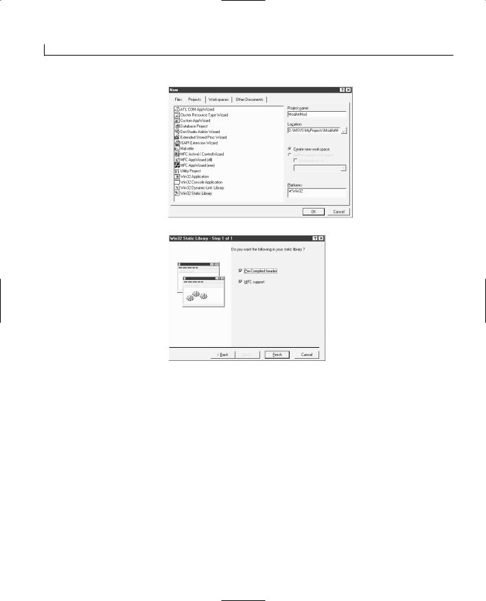

Creating Your Own Classes and Modules |
385 |
and source code file to today’s project by choosing Project | Add To Project \ Files. Once you add both of these files to the project, you should see the CLine class appear in the Class View of your project.
Defining the Classes
Now that you’ve got a basic library module project ready to go, it’s time to begin adding the meat of the module. Using the CLine class is an easy way of reusing some functional-
ity that you created earlier in another setting. However, the real functionality of this mod- 16 ule will be in its ability to generate random drawings, or squiggles. For this functionality,
you’ll need to create a new class.
To start this new class, add a new class to the project by selecting New Class from the pop-up menu in the Class View tab. The first thing that you’ll notice in the New Class dialog is that you are limited to creating generic classes. Because you are creating a static library that will be linked into the application, Visual C++ is making some assumptions about the type of class that you want to create. Because this is not an MFC project, even though MFC support is included, you are prevented from creating a new MFC or form class. If you need to inherit a new class from an MFC class, you have to add it as if it were a generic class.
Use the New Class dialog to create your new class. Give the class a name that reflects its functionality, such as CModArt, and specify that it’s derived from the CObject class as public. You’ll receive the same warning that the base class header file cannot be found, but because you specified that MFC support should be included, you can ignore that message.
Once you create your class, you need to add a couple of variables to the class. First, you need somewhere to hold all the lines that will make up the drawing, so you’ll add an object array. Second, you need to know the area of the drawing surface, so you’ll want a CRect to hold the drawing area specification. You can add both of these variables to your new class using the types and names in Table 16.1.
TABLE 16.1. CModArt VARIABLES.
Type |
Name |
Access |
static const COLORREF |
m_crColors[8] |
Public |
CRect |
m_rDrawArea |
Private |
CObArray |
m_oaLines |
Private |
|
|
|


Creating Your Own Classes and Modules |
389 |
position is within the drawing area. Once you enter the loop, generating all the line segments in the squiggle, you limit the available area for the next destination within 10 of the current position:
pTo.x = ((rand() % 20) - 10) + pFrom.x; pTo.y = ((rand() % 20) - 10) + pFrom.y;
CLine *pLine = new CLine(pFrom, pTo, nCurWidth, m_crColors[nCurColor]); m_oaLines.Add(pLine);
You can easily increase this distance to make the drawings more angular. Once you gen- |
16 |
erate the next line segment, you create the line object and add it to the object array. Finally, you set the starting position to the ending position of the line segment you just generated:
pFrom = pTo;
Now you are ready to go through the loop again and generate the next line segment, until you have generated all line segments in this squiggle.
Now that you can generate a single squiggle, the rest of the process is easy. First, you determine how many squiggles will be in the drawing. Next, you loop for the number of squiggles that need to be generated and call the NewLine function once for each squiggle. To add this functionality to your project, add a new member function to the drawing class. Specify the type as void, the declaration as NewDrawing, and the access as public. Edit the function as in Listing 16.3.
LISTING 16.3. THE CModArt NewDrawing FUNCTION.
1:void CModArt::NewDrawing()
2:{
3:int lNumLines;
4:int lCurLine;
5:
6:// Determine how many lines to create
7:lNumLines = rand() % 10;
8:// Are there any lines to create?
9:if (lNumLines > 0)
10:{
11:// Loop through the number of lines
12:for (lCurLine = 0; lCurLine < lNumLines; lCurLine++)
13:{
14:// Create the new line
15:NewLine();
16:}
17:}
18:}

Creating Your Own Classes and Modules |
391 |
Clearing the Drawing
To provide full functionality, you need to be able to delete a drawing from the drawing class so that a new drawing can be created or an existing drawing can be loaded. This is a simple matter of looping through the object array and destroying every line segment object and then resetting the object array. To add this functionality to your project, add a new member function to the drawing class. Specify the type as void, the declaration as
ClearDrawing, and the access as public. Edit the function as in Listing 16.6.
16
LISTING 16.6. THE CModArt ClearDrawing FUNCTION.
1:void CModArt::ClearDrawing()
2:{
3:// Get the number of lines in the object array
4:int liCount = m_oaLines.GetSize();
5:int liPos;
6:
7:// Are there any objects in the array?
8:if (liCount)
9:{
10:// Loop through the array, deleting each object
11:for (liPos = 0; liPos < liCount; liPos++)
12:delete m_oaLines[liPos];
13:// Reset the array
14:m_oaLines.RemoveAll();
15:}
16:}
Completing the Class
Finally, to wrap up your drawing class, you need to initialize the random number generator. The random number generator function, rand, generates a statistically random number sequence based on a series of mathematical calculations. If the number generator starts with the same number each time, then the sequence of numbers is the same each time. To get the random number generator to produce a different sequence of numbers each time your application runs, you need to seed it with a value that is different each time. The typical way to do this is to feed the current system time into the srand function, which seeds the random number generator with a different time each time that the application runs. This seeding of the number generator must be done only once each time the application is run, so you can add this functionality by editing the drawing class constructor with the code in Listing 16.7.

Creating Your Own Classes and Modules |
393 |
Creating a Test Application
To be able to test your module, you need to create a test application that uses the module. This plain application can contain just enough functionality to thoroughly test the module. All you want to do at this point is test all the functionality in the module; you don’t have to create a full-blown application.
When you create your test application, you need to include the header file for the draw-
ing class in the relevant classes in your application. In a typical SDI or MDI application, 16 this means including the header file in the document class at a minimum and probably
the view and application class source files also. You also have to add the library file that your module created in the application project so that it will be linked into your application.
Creating the Test App Shell
Creating a test application shell is a simple matter of creating a standard SDI or MDI application shell. For the purposes of keeping the test application as simple as possible, it’s probably advisable to use an SDI application. However, if you’ve got some functionality in your module that is intended for use in an MDI application, then that application style might be a better selection as your test application.
For the test application for the sample module you created, create a standard SDI application shell using the AppWizard. Give the project a name such as TestApp or some other suitable name. Specify a file extension on the advanced button on the fourth AppWizard step. Otherwise, just go ahead and use the default settings for everything else.
Once you create the application shell, you need to add the library module to the project. You can do this by selecting Project | Add To Project | Files. Once in the Insert Files dialog, specify the file types as library files, as shown in Figure 16.3. Navigate to the debug directory of the module project to find the library module that you created with the previous project. This typically requires moving up one directory level, finding the project directory for the module, and then navigating through it to the debug directory. (If you are building the release version of the module and application, you want to navigate down to the release directory of the module project.) You should be able to find the library file for the module you created, as shown in Figure 16.4. Select this module and click OK to add it to the project.
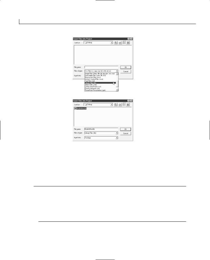
Creating Your Own Classes and Modules |
395 |
classes. In the case of the test application that you are building, this is a variable in the document class of the drawing class that you created in the library module project. To add this variable to your application, add a new member variable to the document class. Specify the variable type as the drawing class from the library module (in this instance, CModArt) and specify the name as m_maDrawing and the access as private.
Creating a New Drawing
The first place where you want to put some of the functionality of your module is when |
16 |
|
you are creating a new document. This is the time to be generating a new drawing. As a |
|
|
result, you want to do two things. First, get the drawing area of the view class, passing it |
|
|
along to the drawing object. Second, tell the drawing object to generate a new drawing. |
|
|
This is all fairly straightforward. To add this functionality to your application, edit the |
|
|
OnNewDocument function in the document class, adding the lines 9–23 in Listing 16.10. |
|
|
LISTING 16.10. THE CTestAppDoc OnNewDocument FUNCTION. |
|
|
|
|
|
1: |
BOOL CTestAppDoc::OnNewDocument() |
|
2: { |
|
|
3: |
if (!CDocument::OnNewDocument()) |
|
4: |
return FALSE; |
|
5: |
|
|
6:// TODO: add reinitialization code here
7:// (SDI documents will reuse this document)
9:// Get the position of the view
10:POSITION pos = GetFirstViewPosition();
11:// Did we get a valid position?
12:if (pos != NULL)
13:{
14:// Get a pointer to the view
15:CView* pView = GetNextView(pos);
16:RECT lWndRect;
17:// Get the display area rectangle
18:pView->GetClientRect(&lWndRect);
19:// Set the drawing area
20:m_maDrawing.SetRect(lWndRect);
21:// Create a new drawing
22:m_maDrawing.NewDrawing();
23:}
24:
25:return TRUE;
26:}

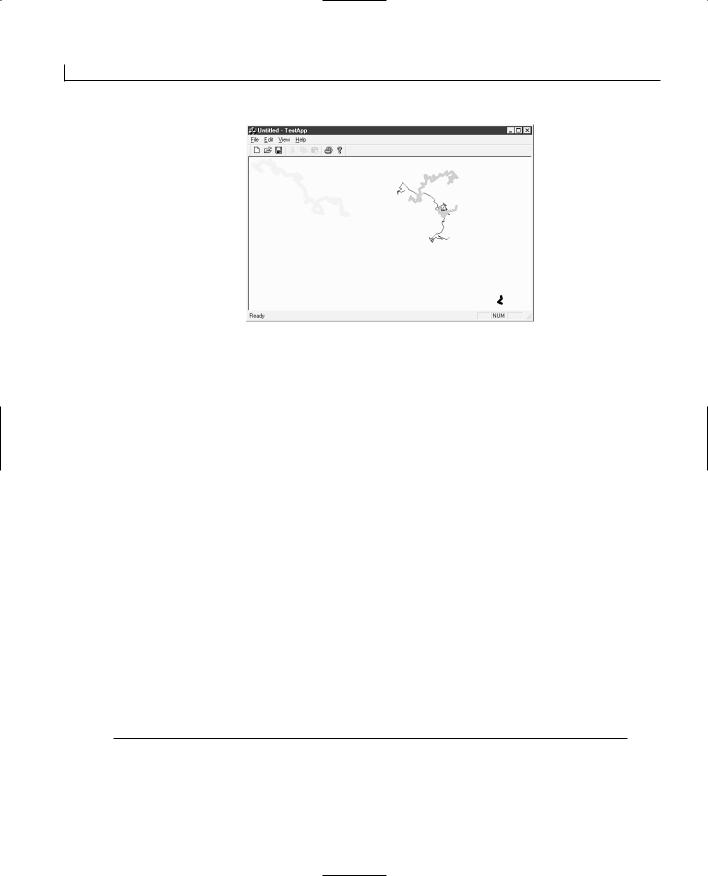

Creating Your Own Classes and Modules |
401 |
64: |
pFrom = pTo; |
65: |
} |
66: |
} |
67: } |
|
Now that you’ve made all the necessary changes to the library module, compile it so that |
|
it’s ready for use in the test application. If you run your test application from the Start | |
16 |
Run Taskbar option, as in Figure 16.6, you’ll notice that there is no noticeable difference |
in how your application behaves. This is because the application hasn’t changed. The application is still using the old version of your library module. To get the test application to use the new version of the library module, reopen the test application project in Visual C++. Build the project, which should not do anything other than relink the project, and then run the application. You should see a significant difference in the drawings that your application is now generating, as shown in Figure 16.7.
FIGURE 16.6.
Run the test application from the Start menu.
FIGURE 16.7.
The updated test application.
Summary
Today you learned about how to approach creating and designing new classes for your applications. You learned the differences between the different types of classes that are available to you through the New Class Wizard in Visual C++. You also learned how you can create a library module with a set of your functionality that you can hand to other


Creating Your Own Classes and Modules |
403 |
Workshop
The Workshop provides quiz questions to help you solidify your understanding of the material covered and exercises to provide you with experience in using what you’ve learned. The answers to the quiz questions and exercises are provided in Appendix B, “Answers.”
Quiz |
16 |
1.When do you want to create a new MFC class?
2.When you make changes to a library file, what do you have to do to the applications that use the library file?
3.What are the different types of classes that you can create?
4.When you package some functionality in a library file, what do you need to give to other programmers who want to use your library module?
5.What are two of the basic principles in object-oriented software design?
Exercise
Separate the CLine class into a different library module from the drawing class so that you have two library modules instead of one. Link them into the test application.


WEEK 3
DAY 17
Sharing Your Functionality with Other Applications—Creating DLLs
Yesterday you learned how you could create a set of functionality that might be useful for multiple applications and how you could package it in a library file that could be linked into those applications. Today you will learn how to do this same thing, only with a much more dynamic package.
Often, a family of applications will have some functionality in common. When you place this shared functionality into DLLs instead of library modules, all the applications can use the same functionality with only a single copy of the functionality distributed in the form of DLLs, instead of duplicating the same functionality in each of the applications. This method saves disk space on any systems where the applications are installed.


Sharing Your Functionality with Other Applications—Creating DLLs |
409 |
or library, a brief description of the DLL, and the names of all functions that are to be exported. This file has to follow a specific format, so you should not modify the default DEF file that is automatically created by the DLL Wizard other than to add exported function names. A typical DEF file follows:
LIBRARY “mydll”
DESCRIPTION ‘mydll Windows Dynamic Link Library’
EXPORTS
; Explicit exports can go here MyFunc1
MyFunc2
If you are using MFC classes in your regular DLLs, you need to call the
macro as the first line of code in all exported functions. This is nec-
essary to make the exported functions threadsafe, which allows your class functions to be 17 called simultaneously by two or more programs (or threads). The AFX_MANAGE_STATE
macro takes a single argument, a pointer to a AFX_MODULE_STATE structure, which can be retrieved by calling the AfxGetStaticModuleState function. A typical exported function that uses MFC looks like the following:
extern “C” void PASCAL EXPORT MyFunc(...)
{
AFX_MANAGE_STATE(AfxGetStaticModuleState()); // normal function body here
.
.
.
}
Designing DLLs
When you are designing your DLLs, you should be aware that any of the functions in your DLLs can be called simultaneously by multiple applications all running at the same time. As a result, all the functionality in any DLLs that you create must be threadsafe.
All variables that hold any values beyond each individual function call must be held and maintained by the application and not the DLL. Any application variables that must be manipulated by the DLL must be passed in to the DLL as one of the function arguments. Any global variables that are manipulated within the DLL may be swapped with variables from other application processes while the function is running, leading to unpredictable results.
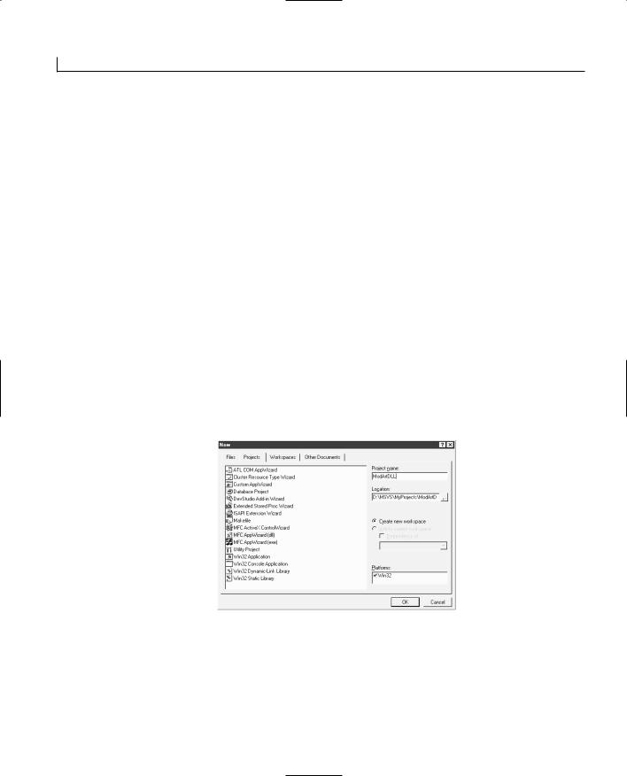
Sharing Your Functionality with Other Applications—Creating DLLs |
411 |
FIGURE 17.2.
Specifying the DLL type.
Open the header file containing the definition of the drawing class. Add the |
17 |
|
AFX_EXT_CLASS macro to the class declaration as shown in Listing 17.1. Remove the |
||
|
||
color table variable from the class declaration also. |
|
LISTING 17.1. THE MODIFIED CModArt CLASS DECLARATION.
1:class AFX_EXT_CLASS CModArt : public CObject
2:{
3:public:
4:void NewDrawing();
5:virtual void Serialize(CArchive &ar);
6:void Draw(CDC *pDC);
7:void ClearDrawing();
8:void SetRect(CRect rDrawArea);
9:CModArt();
10:virtual ~CModArt();
11:
12:private:
13:void NewLine();
14:CRect m_rDrawArea;
15:CObArray m_oaLines;
16:};
You cannot have public static tables in DLLs, so you cannot declare the color table as a public, static member of the drawing class, as it was yesterday. As a result, you’ll move it to a local variable in the NewLine member function. Edit the NewLine function to add this local variable and to reset the function to behave as it did in its initial incarnation,
as in Listing 17.2.


Sharing Your Functionality with Other Applications—Creating DLLs |
413 |
48:{
49:// Add the new line to the object array
50:m_oaLines.Add(pLine);
51:}
52:// Did we run into a memory exception?
53:catch (CMemoryException* perr)
54:{
55:// Display a message for the user, giving him the
56:// bad news
57:AfxMessageBox(“Out of memory”, MB_ICONSTOP | MB_OK);
58:// Did we create a line object?
59:if (pLine)
60:{
61:// Delete it
62:delete pLine;
63:pLine = NULL;
64: |
} |
17 |
|
65:// Delete the exception object
66:perr->Delete();
67:}
68:// Set the starting point to the end point
69:pFrom = pTo;
70:}
71:}
72:}
After making these changes to the drawing class, you are ready to compile your DLL. Once you compile the DLL, switch over to the file explorer, find the DLL in the debug subdirectory under the project directory, and copy the DLL to the debug directory in the test application project directory.
Adapting the Test Application
To adapt the test application to use the DLL, open the test application project that you created yesterday. You are going to delete the library module that you created yesterday and add the LIB file that was created with the DLL. You are also going to change the header file that is included for the drawing class. After making these two changes, your test application will be ready to use with the DLL.
To delete the library module from the project, open the File View in the workspace pane. Select the LIB file from the list of project files and press the Delete key. Once you delete the library file from the project, select Project | Add To Project | Files from the main menu. Specify the Library Files (.lib) file type, and then navigate to the debug directory of the DLL project. Select the LIB file that was created with your DLL, in this case, ModArtDll.lib. Click OK to add the file to the project.

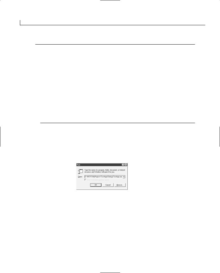


WEEK 3
DAY 18
Doing Multiple Tasks at
One Time—Multitasking
Sometimes it is convenient to let your applications do more than one thing at a time. Your application could write a backup file or print in the background while the user is working on the same document. Your application could perform calculations while the user enters new data or draws multiple images simultaneously. There are many different reasons why you might want to add this capability, called multitasking, to your applications. Windows provides several facilities specifically for building this into applications.
Today, you will learn
●How tasks can be performed while an application is idle.
●How tasks can run independently of the rest of the application.
●How to coordinate access to resources that are shared between multiple independent tasks.
●How to start and stop independently running tasks.
Doing Multiple Tasks at One Time––Multitasking |
431 |
within the whole application. This lets the application accomplish more things simultaneously, such as when Microsoft Word checks your spelling at the same time you are typing your document.
Idle Processing Threads
One of the easiest ways to let your application perform multiple tasks at one time is to add some idle processing tasks. An idle processing task is a task that is performed when an application is sitting idle. Literally, a function in the application class is called when there are no messages in the application message queue. The idea behind this function is that while the application is idle, it can perform work such as cleaning up memory (also known as garbage collection) or writing to a print spool.
The OnIdle function is a holdover from the Windows 3.x days. It is a member of the CWinApp class, from which your application class is inherited. By default, no processing in this function is added by the AppWizard, so if you want this function in your application, you must add it to your application class through the Class Wizard. (OnIdle is one of the available messages for the App class in your applications.)
The OnIdle function receives one argument, which is the number of times the OnIdle func-
tion has been called since the last message was processed by your application. You can 18 use this to determine how long the application has been idle and when to trigger any
functionality that you need to run if the application is idle for more than a certain amount of time.
One of the biggest concerns in adding OnIdle processing to your applications is that any functionality you add must be small and must quickly return control to the user. When an application performs any OnIdle processing, the user cannot interact with the application until the OnIdle processing finishes and returns control to the user. If you need to perform some long, drawn-out task in the OnIdle function, break it up into many small and quick tasks so that control can return to the user; then, you can continue your OnIdle task once the message queue is empty again. This means that you also have to track your application’s progress in the OnIdle task so that the next time the OnIdle function is called, your application can pick up the task where it left off.
Spawning Independent Threads
If you really need to run a long background task that you don’t want interfering with the user, you should spawn an independent thread. A thread is like another application running within your application. It does not have to wait until the application is idle to perform its tasks, and it does not cause the user to wait until it takes a break.

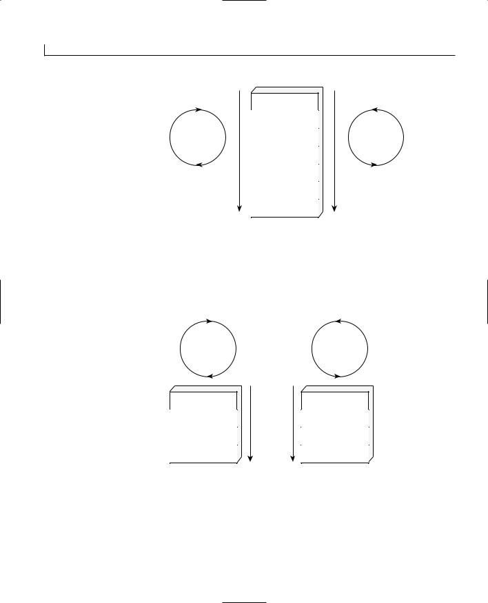
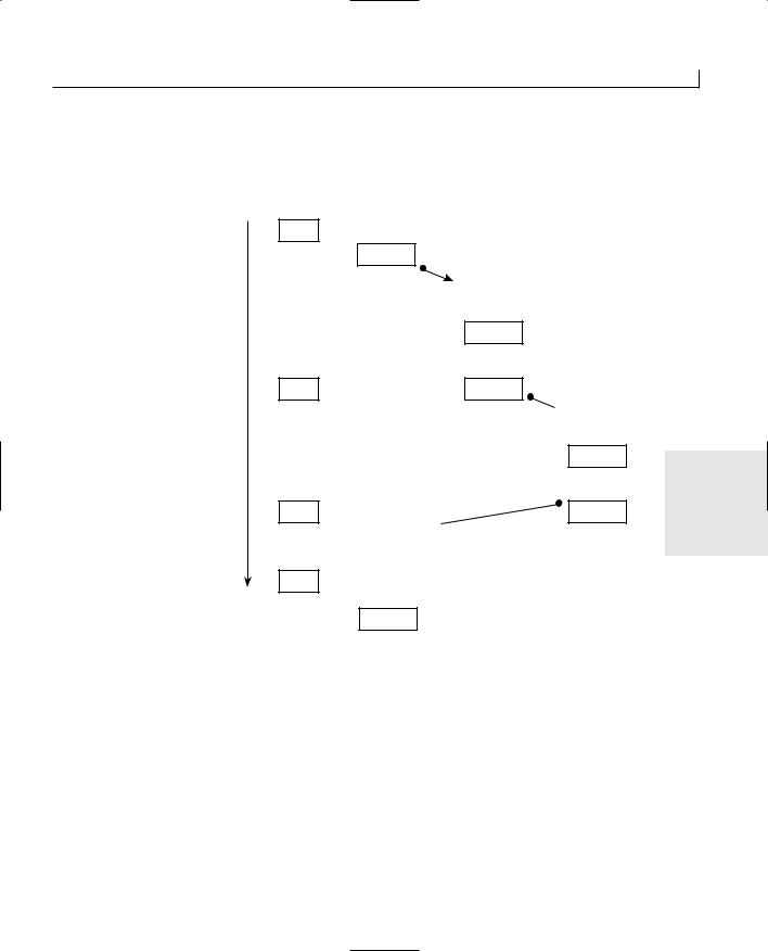
 processor.
 processor. Thread 3 checks the
 processor.
 critical section.
Doing Multiple Tasks at One Time––Multitasking |
439 |
FIGURE 18.5. |
|
|
|
Multiple threads plac- |
|
|
|
ing objects into a |
|
|
|
queue. |
Multiple threads placing |
|
As items are placed into |
|
|
||
|
items into a queue |
|
the queue, the semaphore |
|
|
|
is incremented |
|
|
|
|
|
|
|
|
|
|
|
|
|
|
|
|
|
|
|
|
|
|
|
|
As items are removed from |
A single thread removing |
the queue, the semaphore |
items from the queue for |
is decremented |
processing |
ment is the maximum usage count for the semaphore. You can use these two arguments 18 to control how many threads and processes can have access to a shared resource at any
one time. The third argument is the name for the semaphore, which is used to identify the semaphore by all applications running on the system, just as with the CMutex class. The final argument is a pointer to the security attributes for the semaphore.
With the CSemaphore object, you can use the Lock and Unlock member functions to gain or release control of the semaphore. When you call the Lock function, if the semaphore usage count is greater than zero, the usage count is decremented and your program is allowed to continue. If the usage count is already zero, the Lock function waits until the usage count is incremented so that your process can gain access to the shared resource. When you call the Unlock function, the usage count of the semaphore is incremented.
Events
As much as thread synchronization mechanisms are designed to control access to limited resources, they are also intended to prevent threads from using unnecessary processor cycles. The more threads running at one time, the slower each of those threads performs its tasks. Therefore, if a thread does not have anything to do, block it and let it sit idle, allowing other threads to use more processor time and thus run faster until the conditions are met that provide the idle thread with something to do.
This is why you use events—to allow threads to be idle until the conditions are such that

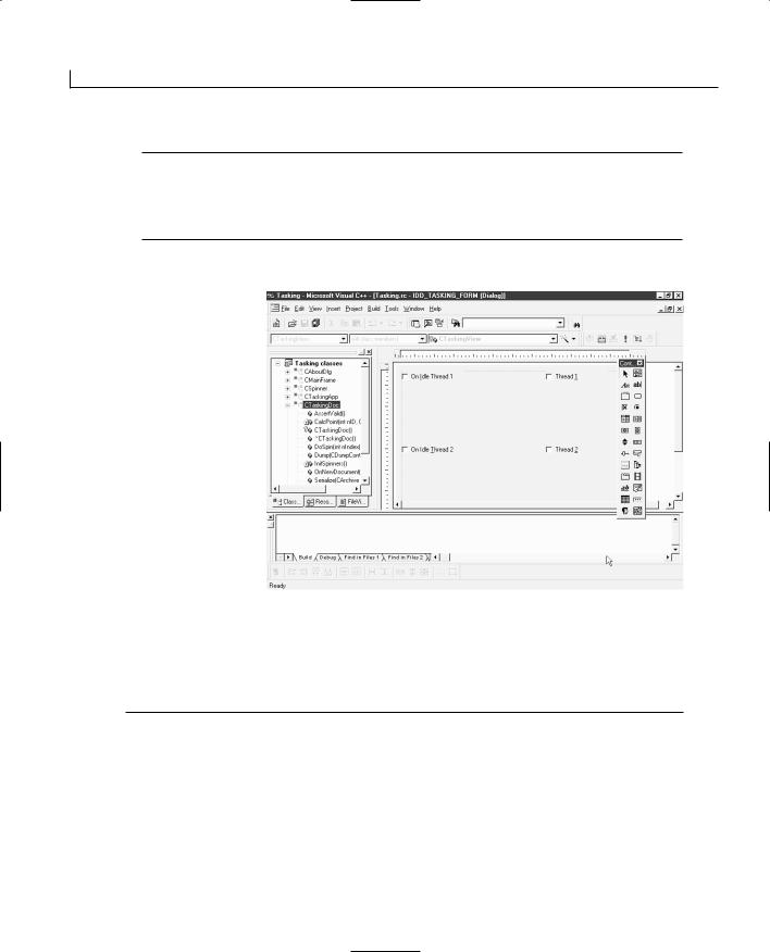


Doing Multiple Tasks at One Time––Multitasking |
447 |
13:// Set the origination point
14:org.x = m_pCenter.x + (m_iRadius / 2);
15:org.y = m_pCenter.y + m_iRadius;
16:// Set the viewport origination point
17:pDC->SetViewportOrg(org.x, org.y);
19:CPoint pEndPoint;
20:// Calculate the angle of the next line
21:double nRadians = (double) (m_nMinute * 6) * 0.017453292;
22:// Set the end point of the line
23:pEndPoint.x = (int) (m_iRadius * sin(nRadians));
24:pEndPoint.y = (int) (m_iRadius * cos(nRadians));
25:
26:
27:// Create the pen to use
28:CPen pen(PS_SOLID, 0, m_crColors[m_crColor]);
29:// Select the pen for use
30:CPen* pOldPen = pDC->SelectObject(&pen);
31:
32:// Move to the starting point
33:pDC->MoveTo (pEndPoint);
34:// Draw the line to the end point
35:pDC->LineTo (pStartPoint);
36: |
18 |
|
|
37: |
// Reselect the previous pen |
38: |
pDC->SelectObject(&pOldPen); |
39: |
|
40:// Release the device context
41:m_pViewWnd->ReleaseDC(pDC);
43:// Increment the minute
44:if (++m_nMinute == 60)
45:{
46:// If the minutes have gone full circle, reset to 0
47:m_nMinute = 0;
48:// Increment the color
49:if (++m_crColor == 8)
50:// If we’ve gone through all colors, start again
51:m_crColor = 0;
52:}
53:}
That was quite a bit of code to type. What does it do? Well, to understand what this function is doing, and how it’s going to make your spinner draw a color wheel on the window, let’s take a closer look at the code.
To make efficient use of the spinner by the different threads, it’ll only draw one line each time the function is called. This function will be called 60 times for each complete circle,
Doing Multiple Tasks at One Time––Multitasking |
449 |
double nRadians = (double) (m_nMinute * 6) * 0.017453292; pEndPoint.x = (int) (m_iRadius * sin(nRadians));
pEndPoint.y = (int) (m_iRadius * cos(nRadians));
In the first of these calculations, convert the minutes into degrees, which can then be fed into the sine and cosine functions to set the x and y coordinates to draw a circle. This sets the end point of the line that will be drawn.
Now that you’ve figured out the starting and ending points of the line, you’ll create a pen to use in drawing the line:
CPen pen(PS_SOLID, 0, m_crColors[m_crColor]);
You’ve specified that the pen will be solid and thin, and you are picking the current color from the color table. Once you create the pen to use, select the pen for drawing, being sure to capture the current pen as the return value from the device context object:
CPen* pOldPen = pDC->SelectObject(&pen);
Now you are ready to draw the line, which is done using the MoveTo and LineTo functions that you’re well familiar with by now. Once the line is drawn, release the device
context so that you don’t have a resource leak in your application:
18
m_pViewWnd->ReleaseDC(pDC);
At this point, you’ve drawn the line, so all that’s left to do is increment the minute counter, resetting it if you’ve made it all the way around the circle. Each time you complete a circle, you increment the color counter until you’ve gone through all eight colors, at which time you reset the color counter.
In order to be able to use the trigonometric functions in this function, include the math.h header file in the Spinner class source file. To add this, scroll up to the top of the source code file and add another #include line, specifying the math.h header file as the file to be included, as in Listing 18.5.
LISTING 18.5. THE CSpinner SOURCE FILE.
1:// Spinner.cpp : implementation of the CSpinner class
2://
3://////////////////////////////////////////////////////////////////////
5:#include “stdafx.h”
6:#include <math.h>
7:#include “Tasking.h”
8:#include “Spinner.h”


Doing Multiple Tasks at One Time––Multitasking |
453 |
function, adding the code in Listing 18.8.
LISTING 18.8. THE CTaskingDoc InitSpinners FUNCTION.
1:void CTaskingDoc::InitSpinners()
2:{
3:inti;
4:
5:// Get the position of the view
6:POSITION pos = GetFirstViewPosition();
7:// Did we get a valid position?
8:if (pos != NULL)
9:{
10:// Get a pointer to the view
11:CView* pView = GetNextView(pos);
13: |
// Loop through the spinners |
|
14: |
for (i = 0; i < 4; i++) |
|
15: |
{ |
|
16: |
// Set the pointer to the view |
|
17: |
m_cSpin[i].SetViewWnd(pView); |
|
18: |
// Initialize the pointer to the continuation indicator |
|
19: |
m_cSpin[i].SetContinue(NULL); |
18 |
20: |
switch (i) |
21:{
22:case 1: // Set the pointer to the first thread
23: |
// continuation indicator |
24:m_cSpin[i].SetContinue(&((CTaskingView*)pView)-
>m_bThread1);
25:break;
26:case 3: // Set the pointer to the second thread
27: |
// continuation indicator |
28:m_cSpin[i].SetContinue(&((CTaskingView*)pView)-
>m_bThread2);
29:break;
30:}
31:// Calculate the location of the spinner
32:CalcPoint(i, &m_cSpin[i]);
33:}
34:}
35:}
In this function, you first went through the steps of getting a pointer to the view class from the document, as you did initially back on Day 10. Once you have a valid pointer to the view, start a loop to initialize each of the spinners in the array. You call the SetViewWnd spinner function to set the spinner’s pointer to the view window and then initialize the spinner’s pointer to the check box variable to NULL for all spinners. If the
Doing Multiple Tasks at One Time––Multitasking |
455 |
5:
6:// TODO: add reinitialization code here
7:// (SDI documents will reuse this document)
9:///////////////////////
10:// MY CODE STARTS HERE
11:///////////////////////
13:// Initialize the spinners
14:InitSpinners();
15:
16:///////////////////////
17:// MY CODE ENDS HERE
18:///////////////////////
20:return TRUE;
21:}
Spinning the Spinner
Once last thing that you’ll add to the document class for now is a means of calling the Draw function for a specific spinner from outside the document class. Because the array
of spinners was declared as a private variable, no outside objects can get access to the 18 spinners, so you need to add access for the outside objects. You can add a function to
provide this access by adding a new member function to your document class. Specify the function type as void, specify the function declaration with a name and a single integer argument for the spinner number, such as DoSpin(int nIndex), and then specify the function’s access as public. Once you have added the function, you can add the code in Listing 18.10 to the function to perform the actual call to the specified spinner.
LISTING 18.10. THE CTaskingDoc DoSpin FUNCTION.
1:void CTaskingDoc::DoSpin(int nIndex)
2:{
3:// Spin the Spinner
4:m_cSpin[nIndex].Draw();
5:}
Adding the OnIdle Tasks
Now that you have the supporting functionality in place, it’s time to turn your attention to adding the various threads that will turn the various spinners. The first threads to add are the ones executing while the application is idle. You’ll add a clicked event handler for the two On Idle check boxes so that you can keep the variables for these two check boxes in sync with the window. You’ll also add the code to the application’s OnIdle func-

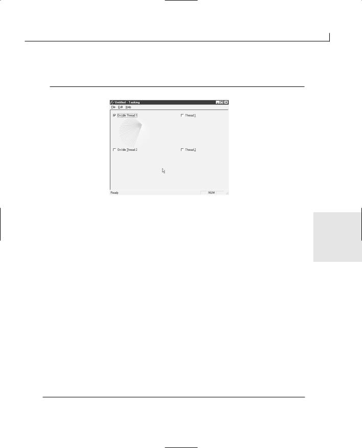
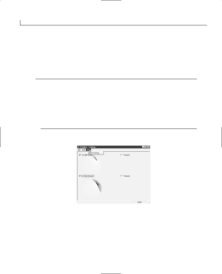
Doing Multiple Tasks at One Time––Multitasking |
461 |
Adding Independent Threads
Now that you’ve seen what is involved in adding an OnIdle task, it’s time to see what’s involved in adding an independent thread to your application. To add a thread to your application, you’ll add a main function for the threads. You’ll also add the code to start and stop the threads. Finally, you’ll add the code to the independent thread check boxes to start and stop each of these threads.
Creating the Main Thread Function
Before you can spin off any independent threads, the thread must know what to do. You will create a main thread function to be executed by the thread when it starts. This function will act as the main function for the thread, and the thread will end once the function ends. Therefore, this function must act as the primary control of the thread, keeping the thread running as long as there is work for the thread to do and then exiting once the thread’s work is completed.
When you create a function to be used as the main function for a thread, you can pass a single parameter to this function. This parameter is a pointer to anything that contains all the information the thread needs to perform its tasks. For the application you’ve been
building in this chapter, the parameter can be a pointer to the spinner that the thread will 18 operate. Everything else that the thread needs can be extracted from the spinner object.
Once the thread has a pointer to its spinner, it can get a pointer to the check box variable that tells it whether to continue spinning or stop itself. As long as the variable is TRUE, the thread should continue spinning.
To add this function to your application, add a new member function to the document class in your application. Specify the function type as UINT, the function declaration as ThreadFunc(LPVOID pParam), and the access as private. You’ll start the thread from within the document class, so there’s no need for any other classes to see this function. Once you’ve added this function, edit it with the code in Listing 18.14.
LISTING 18.14. THE CTaskingDoc ThreadFunc FUNCTION.
1:UINT CTaskingDoc::ThreadFunc(LPVOID pParam)
2:{
3:// Convert the argument to a pointer to the
4:// spinner for this thread
5:CSpinner* lpSpin = (CSpinner*)pParam;
6:// Get a pointer to the continuation flag

Doing Multiple Tasks at One Time––Multitasking |
463 |
12:::WaitForSingleObject (hThread, INFINITE);
13:}
14:}
15: |
else |
// We are running the thread |
16:{
17:int iSpnr;
18:// Which spinner to use?
19:switch (nIndex)
20:{
21:case 0:
22:iSpnr = 1;
23:break;
24:case 1:
25:iSpnr = 3;
26:break;
27:}
28:// Start the thread, passing a pointer to the spinner
29:m_pSpinThread[nIndex] = AfxBeginThread(ThreadFunc,
30:(LPVOID)&m_cSpin[iSpnr]);
31:}
32:}
The first thing that you do in this function is check to see if the thread is being stopped |
18 |
|
|
or started. If the thread is being stopped, check to see if the pointer to the thread is valid. |
|
If the pointer is valid, you retrieve the handle for the thread by reading the value of the |
|
handle property of the CWinThread class: |
|
HANDLE hThread = m_pSpinThread[nIndex]->m_hThread; |
|
|
|
Once you have the handle, you use the handle to wait for the thread to stop itself with the |
|
WaitForSingleObject function. |
|
::WaitForSingleObject (hThread, INFINITE); |
|
The WaitForSingleObject function is a Windows API function that tells the operating sys- |
|
tem you want to wait until the thread, whose handle you are passing, has stopped. The |
|
second argument to this function specifies how long you are willing to wait. By specify- |
|
ing INFINITE, you tell the operating system that you will wait forever, until this thread |
|
stops. If you specify a timeout value, and the thread does not stop by the time you |
|
specify, the function returns a value that indicates whether the thread has stopped. |
|
Because you specify INFINITE for the timeout period, you don’t need to worry about cap- |
|
turing the return value because this function does not return until the thread stops. |
|
If the thread is being started, you determine which spinner to use and then start that |
|
thread by calling the AfxBeginThread function. |
|
m_pSpinThread[nIndex] = AfxBeginThread(ThreadFunc, |
|

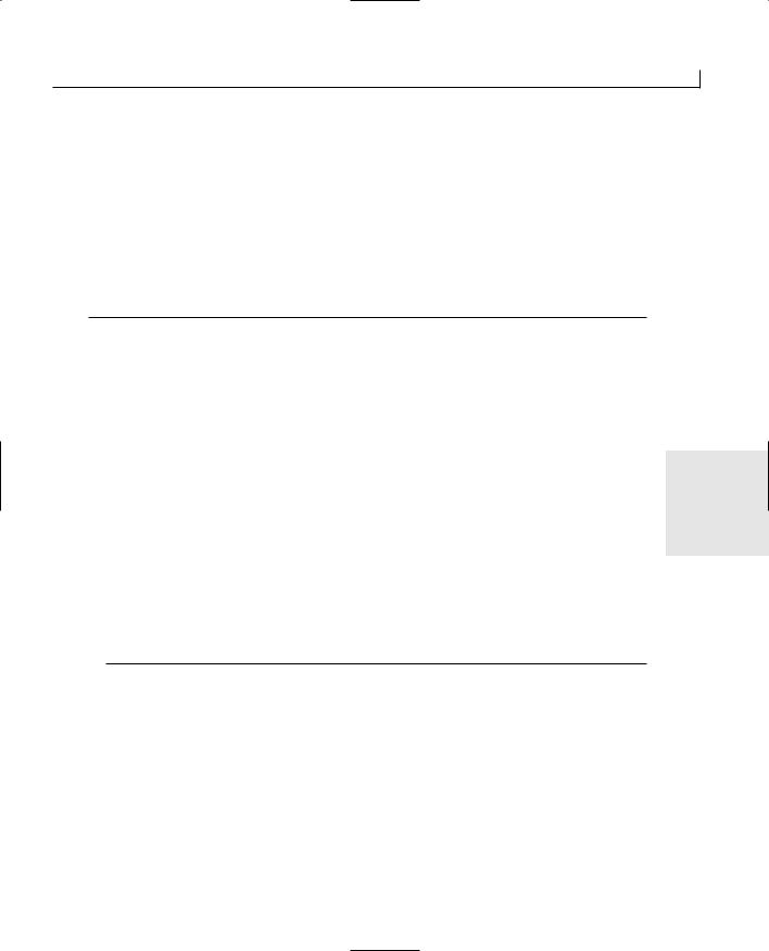
Doing Multiple Tasks at One Time––Multitasking |
465 |
In this function, the first thing that you do is to call UpdateData to keep the variables in sync with the controls on the window. Next, you retrieve a pointer to the document. Once you have a valid pointer, you call the document’s SuspendSpinner function, specifying the first thread and passing the current value of the variable tied to this check box to indicate whether the thread is to be started or stopped.
To add this same functionality to the other thread check box, perform the same steps, adding the code in Listing 18.17.
LISTING 18.17. THE CTaskingView OnCbthread2 FUNCTION.
1:void CTaskingView::OnCbthread2()
2:{
3:// TODO: Add your control notification handler code here
5:///////////////////////
6:// MY CODE STARTS HERE
7:///////////////////////
9:// Sync the variables with the dialog
10:UpdateData(TRUE);
11: |
18 |
|
12:// Get a pointer to the document
13:CTaskingDoc* pDocWnd = (CTaskingDoc*)GetDocument();
14:// Did we get a valid pointer?
15:ASSERT_VALID(pDocWnd);
16:
17:// Suspend or start the spinner thread
18:pDocWnd->SuspendSpinner(1, m_bThread2);
20:///////////////////////
21:// MY CODE ENDS HERE
22:///////////////////////
23:}
Now that you’ve added the ability to start and stop the independent threads, compile and run your application. You’ll see that you can start and stop the independent threads with their check boxes, as well as the OnIdle tasks.
At this point, if you play around with your application for a while, you’ll notice a bit of a
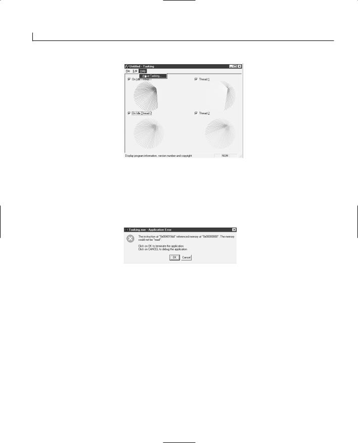

Doing Multiple Tasks at One Time––Multitasking |
467 |
you should eliminate before allowing anyone else to use the application.
What you need to do to prevent this error is stop both of the threads before allowing the application to close. The logical place to take this action is the OnDestroy event message processing in the view class. This event message is sent to the view class to tell it to clean up anything that it needs to clean up before closing the application. You can add code to set both of the check box variables to FALSE so that the threads will stop themselves and then call the SuspendSpinner function for each thread to make sure that both threads have stopped before allowing the application to close. You do not need to call UpdateData to sync the variables with the controls because the user doesn’t need to see when you’ve change the value of either check box.
To add this functionality to your application, add an event-handler function for the OnDestroy event message to the view class. This function does not normally exist in the view class that is created by the AppWizard, so you need to add it when it is needed in the descendent view class. Edit the function, adding the code in Listing 18.18.
LISTING 18.18. THE CTaskingView OnDestroy FUNCTION.
|
|
|
18 |
1: void CTaskingView::OnDestroy() |
|||
2: { |
|
|
|
3: |
CFormView::OnDestroy(); |
|
|
4: |
|
|
|
5: |
// TODO: Add your message handler code here |
|
|
6: |
|
|
|
7:///////////////////////
8:// MY CODE STARTS HERE
9:///////////////////////
10:
11:// Is the first thread running?
12:if (m_bThread1)
13:{
14:// Specify to stop the first thread
15:m_bThread1 = FALSE;
16:// Get a pointer to the document
17:CTaskingDoc* pDocWnd = (CTaskingDoc*)GetDocument();
18:// Did we get a valid pointer?
19:ASSERT_VALID(pDocWnd);
20:
21:// Suspend the spinner thread
22:pDocWnd->SuspendSpinner(0, m_bThread1);
23:}
24:// Is the second thread running?
25:if (m_bThread2)
26:{
27:// Specify to stop the second thread

Doing Multiple Tasks at One Time––Multitasking |
469 |
also learned how to create independent threads in your application that will perform their tasks completely independently of the rest of the application. You implemented an application that uses both of these approaches so that you could experience how each approach works.
Q&A
QHow can I use the other version of the AfxBeginThread to encapsulate a thread in a custom class?
AFirst, the other version of AfxBeginThread is primarily for creating user-interface threads. The version that you used in today’s sample application is for creating what are called worker threads that immediately take off on a specific task. If you want to create a user-interface thread, you need to inherit your custom class from the CWinThread class. Next, override several ancestor functions in your custom class. Once the class is ready to use, you use the RUNTIME_CLASS macro to get a pointer to the runtime class of your class and pass this pointer to the AfxBeginThread function, as follows:
CWinThread* pMyThread = |
18 |
AfxBeginThread(RUNTIME_CLASS(CMyThreadClass)); |
QCan I use SuspendThread and ResumeThread to start and stop my independent threads in my sample application?
AYes, but you need to make a few key changes to your application. First, in the OnNewDocument function, initialize the two thread pointers to NULL, as shown in Listing 18.19.
LISTING 18.19. THE MODIFIED CTaskingDoc OnNewDocument FUNCTION.
1:BOOL CTaskingDoc::OnNewDocument()
2:{
3:if (!CDocument::OnNewDocument())
4:return FALSE;
5:
6:// TODO: add reinitialization code here
7:// (SDI documents will reuse this document)
9:///////////////////////
10:// MY CODE STARTS HERE
11:///////////////////////
13:// Initialize the spinners
14:InitSpinners();
15:
Doing Multiple Tasks at One Time––Multitasking |
471 |
10:m_pSpinThread[nIndex]->SuspendThread();
11:}
12:}
13: |
else |
// We are running the thread |
14:{
15:// Is the pointer for the thread valid?
16:if (m_pSpinThread[nIndex])
17:{
18:// Resume the thread
19:m_pSpinThread[nIndex]->ResumeThread();
20:}
21:else
22:{
23:int iSpnr;
24:// Which spinner to use?
25:switch (nIndex)
26:{
27:case 0:
28:iSpnr = 1;
29:break;
30:case 1:
31:iSpnr = 3;
32:break;
33: |
} |
18 |
|
|
|
||
34: |
|
// Start the thread, passing a pointer to the spinner |
|
35: |
|
m_pSpinThread[nIndex] = AfxBeginThread(ThreadFunc, |
|
36: |
|
(LPVOID)&m_cSpin[iSpnr]); |
|
37: |
} |
|
|
38: |
} |
|
|
39: } |
|
|
|
|
|
|
|
Workshop
The Workshop provides quiz questions to help you solidify your understanding of the material covered and exercises to provide you with experience in using what you’ve learned. The answers to the quiz questions and exercises are provided in Appendix B, “Answers.”
Quiz
1.When is the OnIdle function called?
2.How can you cause the OnIdle function to be repeatedly called while the application is sitting idle?
3.What is the difference between an OnIdle task and a thread?
4.What are the four thread synchronization objects?
5.Why shouldn’t you specify a higher than normal priority for the threads in your
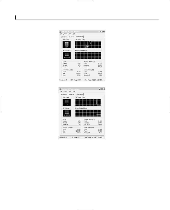

WEEK 2
DAY 19
Building Your Own
Widgets—Creating
ActiveX Controls
The software industry has seen a revolution over the past couple years. How software is built and packaged has moved from a model where all applications are large, monolithic pieces of executable code to a model where most applications consist of small building blocks. These small building blocks, often called components, can be created using any of several different languages and can take many different forms. One of the most popular components is the ActiveX control. If you know how to create your own ActiveX controls, you can build your own components and provide them to other programmers. Today, you will learn
●How to use the Visual C++ wizards to build ActiveX controls.
●How to add properties and methods to your controls using the Class Wizard.
●How to test your control using the tools provided with Visual C++.


Building Your Own Widgets—Creating ActiveX Controls |
475 |
properties are specific to your control and are directly related to the functionality of your control.
You can specify any properties you need in your control using the Automation tab on the Class Wizard. When you add a new property to your control through the Class Wizard, you’ll specify several aspects of the property.
The first aspect is the external property name, which is the name shown to the containing application for the property. Another aspect that you can specify is the internal variable name, which is used in your code, but only if the property is implemented as a member variable. You also specify the variable type for the property.
If you specify that the property is to be implemented as a member variable (the property is a member variable of the control class), then you can specify the name of the notification function, which is called when the property is changed by the containing application. If the property is not a member variable of the control class, you need to specify that it is altered and viewed through Get and Set methods, where the containing application calls a Get method to get the current value of the property and calls a Set method to change the value of the property. If the property is maintained through Get and Set methods, then you can specify the names of these two methods.
For all these aspects of a property, the Add Property dialog suggests appropriate names for everything once you enter the external name for the property. If you want to accept the default names, the only things you need to specify are the external name, the type, and whether the property is a member variable or uses Get and Set methods. If you choose a stock property from the list of available stock properties, the rest of the ele-
ments are automatically specified for you. Once you specify all of this information, the 19 Class Wizard adds all of the necessary code and variables to your control project.
Methods
Methods are functions in the control that can be called by the container application. These functions are made available to other applications through the IDispatch interface, which we discussed on Day 9. Because of the way the IDispatch works in calling the methods in a control, the variables passed to the method have to be packaged in a structure that is passed to the control. This structure is machine independent so that it doesn’t matter whether your control is running with Windows 95/98 on an Intel Pentium II or on a Windows NT with a MIPS or Alpha processor; the structure will look the same. It is the responsibility of each side of the function call to convert the parameters as necessary to fit them into the structure correctly or to extract them from the structure. This process of packaging the method parameters is called marshaling.

Building Your Own Widgets—Creating ActiveX Controls |
477 |
expose the maximum number of squiggles that the control will draw, as well as the maximum length of the squiggles, as properties that the container application can set. Every time the control is clicked, you’ll program it to create a new squiggle drawing. You’ll also add a method to load a squiggle drawing into the control that was created with the previous versions of the squiggle module. Finally, you’ll have the control fire an event to let the container application know that the control has loaded the drawing.
Building the Control Shell
You’ve probably noticed by now that one of the options on the new project dialog is an MFC ActiveX Control Wizard. This is another project wizard just like the AppWizard for creating application and DLL projects. You can use it to build a shell for any ActiveX controls that you want to build. It will create all of the necessary files and configure the project so that the compiler will build an ActiveX control when you compile.
When you start the Control Wizard, you are asked some simple questions about your control project, such as how many controls will be in the project and whether the controls will have runtime licenses.
Note |
Runtime licenses are a means of making sure that the user of your control |
|
has purchased a license to use the control. Controls developed for selling to |
|
|
|
|
|
|
developers often have runtime licenses. The license prevents use of a control |
|
|
by users who haven’t paid for it. When you use the control in an applica- |
|
|
tion, either the runtime license for the control is installed in the user’s |
|
|
registry by the install routine or the runtime license is compiled into the |
|
|
application. These means prevent someone from using the control to build |
19 |
|
new applications. |
|
|
|
|
In the second step of the Control Wizard, the questions get a little more involved but are still fairly easy to answer. In this step, you can click the Edit Names button to provide the control with descriptive names for the user. At the bottom of the Control Wizard, you’ll find a combo box that lists a number of window classes that you can subclass in your control. If you want to create a special edit box that performs some special edits on anything the user types into the box, you choose EDIT from the list of window classes in the drop-down portion of this combo box. If you choose to click the Advanced button, the questions about your project require a fairly thorough understanding of ActiveX controls.
To begin the sample control project today, start a new project, selecting the MFC ActiveX Control Wizard and giving the project a suitable name, such as Squiggle, as shown in Figure 19.1.
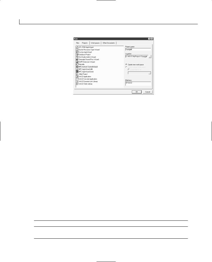
Building Your Own Widgets—Creating ActiveX Controls |
479 |
You need to provide a way for these variables to be retrieved and updated from the exposed properties. This means that you’ll need functions for getting the current value, and for setting the new value, for each of these variables. To add these functions for the m_iLength variable, add a member function to the CModArt class, specifying the type as int, the declaration as GetLength, and the access as public. Edit the function with the code in Listing 19.1.
LISTING 19.1. THE CModArt GetLength FUNCTION.
1:int CModArt::GetLength()
2:{
3:// Return the current value for the m_iLength variable
4:return m_iLength;
5:}
Next, add another member function to the CModArt class, specifying the function type as void, the declaration as SetLength(int iLength), and the access as public. Edit this function, adding the code in Listing 19.2.
LISTING 19.2. THE CModArt SetLength FUNCTION.
1: void CModArt::SetLength(int iLength) 2: {
3: // Set the current value for the m_iLength variable 4: m_iLength = iLength;
5: }
19
Add the same two functions for the m_iSegments variable so that it can also be exposed as a property of the control.
Now that you have made these two properties available for the control, you’ll make sure that they have been initialized to reasonable values before the control is used. To initialize these values, modify the CModArt constructor as in Listing 19.3.
LISTING 19.3. THE MODIFIED CModArt CONSTRUCTOR.
1:CModArt::CModArt()
2:{
3:// Initialize the random number generator
4:srand((unsigned)time(NULL));
5:// Initialize the property variables
6:m_iLength = 200;
7:m_iSegments = 50;
8:}
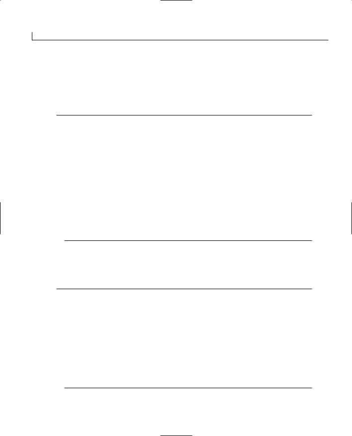
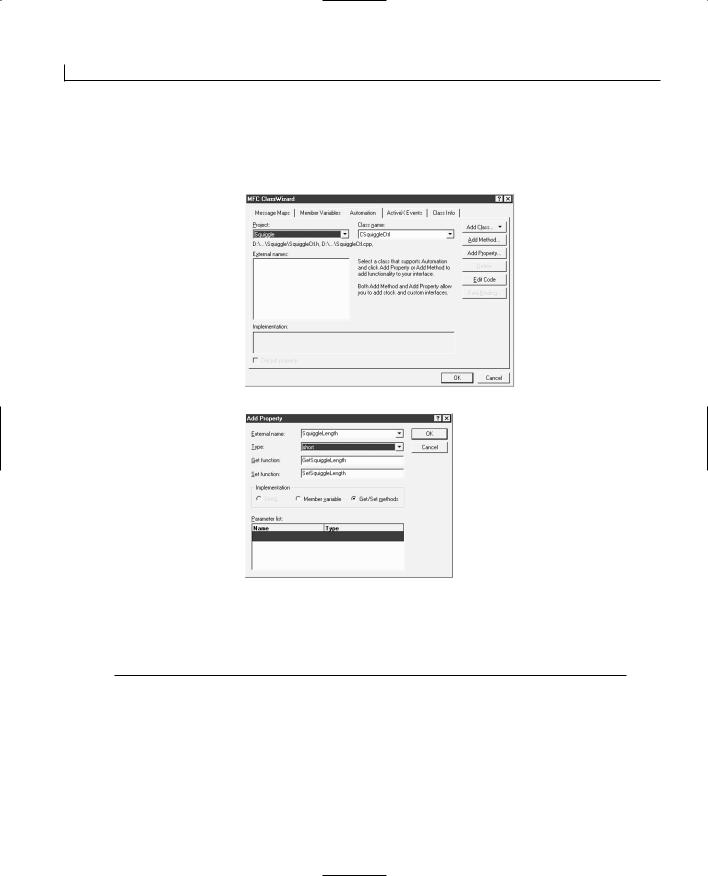
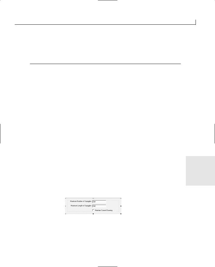
Building Your Own Widgets—Creating ActiveX Controls |
483 |
9: {
10:// TODO: Add your property handler here
11:// Set the new length value
12:m_maDrawing.SetLength(nNewValue);
13:SetModifiedFlag();
14:}
Add another property for the number of squiggles in a drawing by following the same steps, substituting an appropriate property name, such as NumberSquiggles.
One last property you might want to add to your control is a boolean property that the container application could use to keep the control from creating any new drawings and to keep the current drawing visible. Add a new property through the Class Wizard, giving it a suitable name such as KeepCurrentDrawing, and specify the type as BOOL. Leave this property set as a member variable and click OK. The Class Wizard automatically adds the variable to the control class, along with all of the necessary code to maintain the variable.
Designing and Building the Property Page
You need to provide a property page with your control that developers can use when they are working with your control. This property page will provide the users with a means of setting the properties of the control, even if their own development tools do not provide them with a facility to get to these properties in any way other than with code.
Adding a property page to your control is pretty easy. If you select the Resources view
tab in the workspace and expand the dialog folder, you’ll see a dialog for your control’s 19 property page already in the folder. Open this dialog, and you’ll find that it’s a standard
dialog window that you can design using the standard controls available in the dialog designer. To design the property page for your sample control, lay out the property page dialog as shown in Figure 19.4, using the property settings in Table 19.2.
FIGURE 19.4.
The control property page layout.
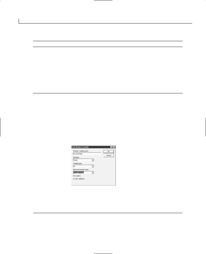

Building Your Own Widgets—Creating ActiveX Controls |
485 |
Click the OK button to add all these variables to the control property page class.
Adding Basic Control Functionality
The basic functionality that your control needs is the ability to respond to mouse clicks by generating a new drawing. To control this behavior, you’ll add a second boolean variable to the control class so that the OnDraw function knows that a mouse click has been triggered. The easiest place to get the drawing area of the control is the OnDraw function, so this is where the new drawing needs to be generated. Do you want the control to generate a new drawing every time the user moves the application using your control in front of another application? Probably not. You will most likely want a greater amount of control over the behavior of the control, so it makes sense to add this second boolean variable. Add a member variable to the control class (CSquiggleCtrl), specifying the variable type as BOOL, the variable name as m_bGenNewDrawing, and the variables access as private.
Before you start adding the code to perform all the various tasks, it’s important that you initialize all the member variables in the control class. This consists of the member variable property, m_keepCurrentDrawing, and the member variable that you just added, m_bGenNewDrawing. You’ll want your control to generate a new drawing right off the bat, and you probably don’t want it to maintain any drawings, unless the container application explicitly specifies that a drawing is to be maintained. You’ll set these two variables accordingly in the control class constructor, as shown in Listing 19.8.
LISTING 19.8. THE CSquiggleCtrl CONSTRUCTOR.
19
1:CSquiggleCtrl::CSquiggleCtrl()
2:{
3:InitializeIIDs(&IID_DSquiggle, &IID_DSquiggleEvents);
5:// TODO: Initialize your control’s instance data here.
6:// Initialize the variables
7:m_bGenNewDrawing = TRUE;
8:m_keepCurrentDrawing = FALSE;
9:}
Next, you’ll add the code to generate and display the squiggle drawings. The place to add this functionality is the OnDraw function in the control class. This function is called every time that the control needs to draw itself, whether it was hidden or something triggered the redrawing by calling the Invalidate function on the control. Once in the OnDraw function, you’ll determine whether you need to generate a new drawing or just draw the existing drawing. Another thing to keep in mind is that you are responsible for drawing

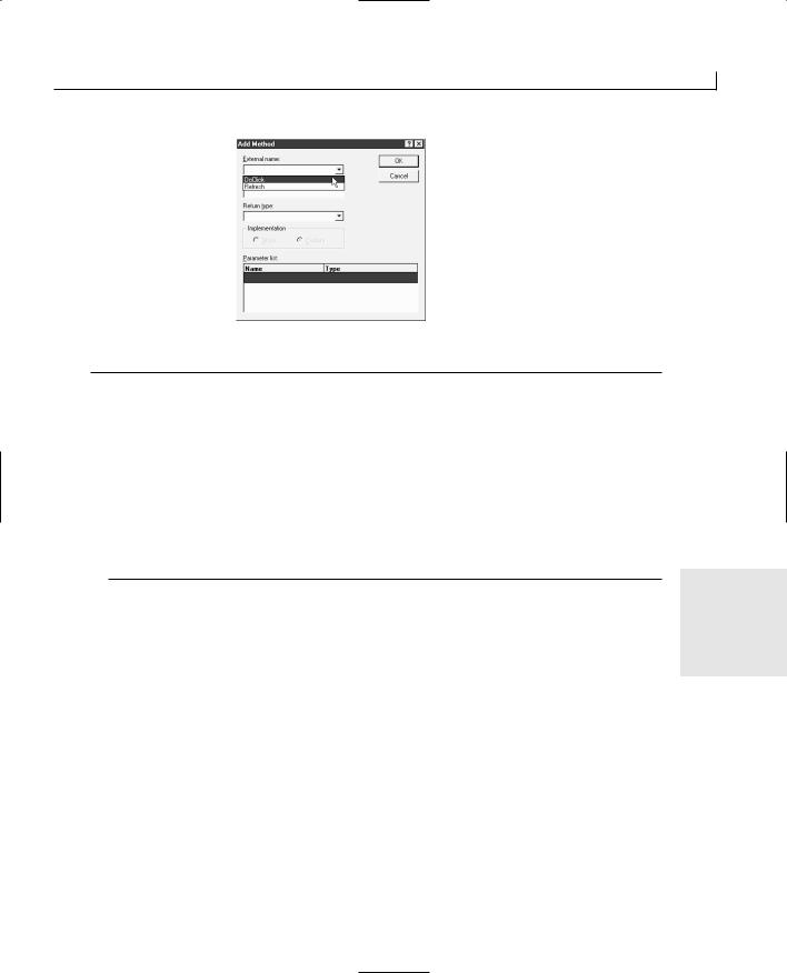
Building Your Own Widgets—Creating ActiveX Controls |
487 |
FIGURE 19.6.
The Add Method dialog.
LISTING 19.10. THE CSquiggleCtrl OnClick FUNCTION.
1:void CSquiggleCtrl::OnClick(USHORT iButton)
2:{
3:// TODO: Add your specialized code here and/or call the base class
4:// Can we generate a new drawing?
5:if (!m_keepCurrentDrawing)
6:{
7:// Set the flag so a new drawing will be generated
8:m_bGenNewDrawing = TRUE;
9:// Invalidate the control to trigger the OnDraw function
10:Invalidate();
11:}
12:COleControl::OnClick(iButton);
13:}
19
In the OnClick function, you check to see whether you could generate a new drawing or maintain the current drawing. If you could generate a new drawing, you set the m_bGenNewDrawing flag to TRUE and invalidated the control, which triggers the OnDraw function.
Adding Methods
Remember the functionality that you are going to give your control: One of the functions is loading a squiggle drawing created with the version of the Squiggle module that you created on Day 16. To add this functionality, you’ll add a method to the control that the container application can call to pass a filename to be loaded. You’ve already added one method to your application, a stock method. Adding a custom method is similar, but you have to provide a little more information to the Add Method dialog.
In the method to load an existing drawing, you’ll create a CFile object for the filename that was passed as a parameter. The CFile constructor will take the filename and the flag
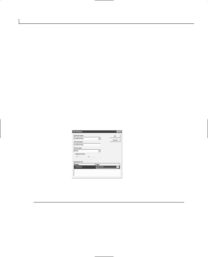
Building Your Own Widgets—Creating ActiveX Controls |
489 |
8:// Create a CArchive object to load the file
9:CArchive lArchive(&lFile, CArchive::load);
10:// Load the file
11:m_maDrawing.Serialize(lArchive);
12:// Make sure that the loaded drawing won’t be overwritten
13:m_bGenNewDrawing = FALSE;
14:// Draw the loaded drawing
15:Invalidate();
16:}
17:catch (CFileException err)
18:{
19:return FALSE;
20:}
21:return TRUE;
22:}
Adding Events
The final part of building your control is adding the events that your control will trigger in the container application. When using your control, the user will be able to add code to be triggered on these events. Adding these events to your control is done through the ActiveX Events tab of the Class Wizard. If you want to add a stock event to be triggered by your control, then you just click the Add Event button and select a stock event from the drop-down list of stock events. If you need to add a custom event to your control, then in the Add Event dialog, instead of selecting a stock event, you enter the name of your custom event. At the bottom of the Add Event dialog is an area for adding parame-
ters that you can pass from your control to the container application with the event.
19
For the sample control, you’ll add one event, a custom event to let the application know that the drawing file specified has been loaded. To add this event, open the Class Wizard and select the ActiveX Events tab, as shown in Figure 19.8. Click the Add Event button to add the event. Enter the name for your custom event, FileLoaded. You’ll notice that the Add Event dialog automatically builds an internal name for the event, in this case, FireFileLoaded, as shown in Figure 19.9. This internal name is the name for the function that you need to call in your code when you want to trigger this event. Click the OK button to add this event. To add a stock event, select the desired stock event from the dropdown list of stock events, and click the OK button to add this second event.
Now that you’ve added your event to your control, you need to make the necessary changes to the code to trigger this event at the appropriate places. You’ll trigger your
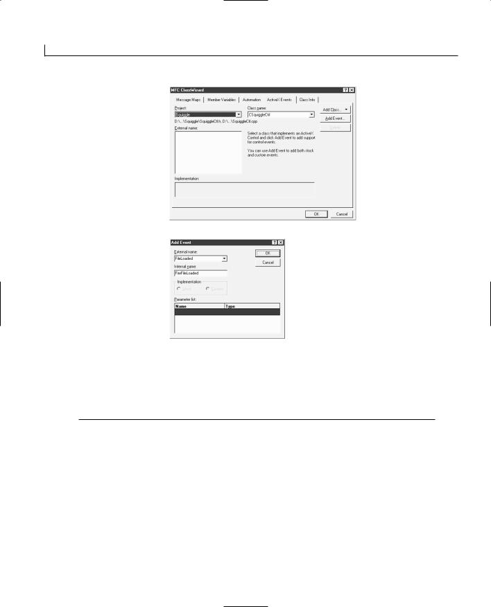
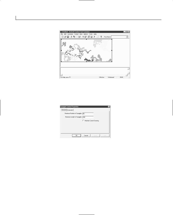
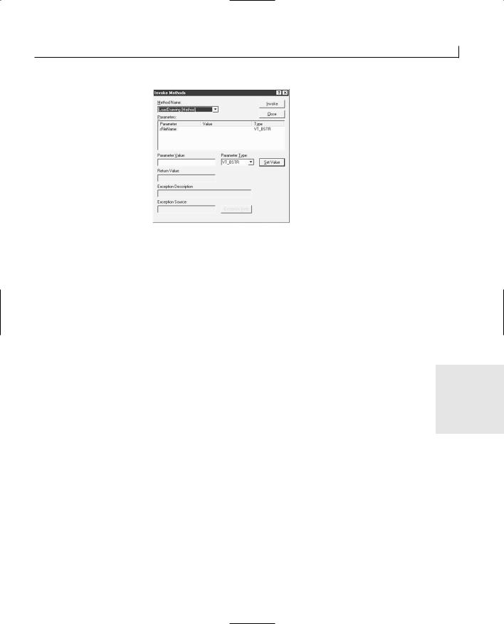
Building Your Own Widgets—Creating ActiveX Controls |
493 |
FIGURE 19.13.
The Invoke Methods dialog.
Finally, to test the methods that you added to your control, select Control | Invoke Methods. This opens the Invoke Methods dialog, as shown in Figure 19.13. In here, you can select from the list of available methods in your control, entering each of the parameters required for the methods, and then click the Invoke button to call that method. You can watch as your methods are called and your control responds.
Summary
Today, you learned how you can use the tools and wizards in Visual C++ to build ActiveX controls with little effort on your part. You learned how you can create the shell of the control project using the Control Wizard. You also learned how you can use the
Class Wizard to add properties, methods, and events to your control. You saw how you |
19 |
|
|
can design a property page for your control and how you can use the Class Wizard to |
|
attach the controls on this dialog to the properties you defined for your control without |
|
having to add any code. Finally, you learned how you can use the ActiveX Control Test |
|
Container to test your control, triggering all the functionality by using the tools of this |
|
utility. |
|
Q&A
Q How do I change the icon that appears in the toolbox for my control?
AIn the Resource View tab of the workspace pane, open the Bitmap folder. You should find a single bitmap in this folder. This image is displayed in the toolbox for your control when you add it to a Visual C++ or Visual Basic project. You should edit this bitmap so that it displays the image that you want to represent your control.


WEEK 3
DAY 20
Internet Applications and
Network Communications
Thanks in part to the explosion in popularity of the Internet, more applications have the ability to communicate with other applications over networks, including the Internet. With Microsoft building networking capabilities into its operating systems, starting with Windows NT and Windows 95, these capabilities are becoming commonplace in all sorts of applications.
Some applications perform simple networking tasks such as checking with a Web site to see whether there are any updates to the program and giving the user the option of updating her copy of the program. Some word processing applications will format documents as Web pages, giving the user the option of loading the pages onto the Web server. You’ve got computer games that allow the user to play against another person halfway around the world instead of just competing against the game itself.
Applications can have any number of networking functions, and they all are built around the Winsock interface. If you know and understand how to program using the Winsock interface and the MFC Winsock classes, this entire
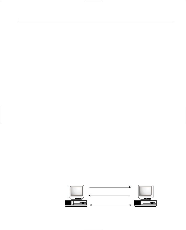
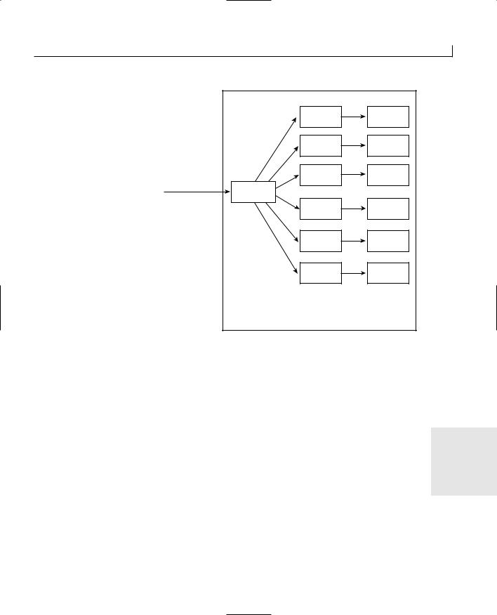


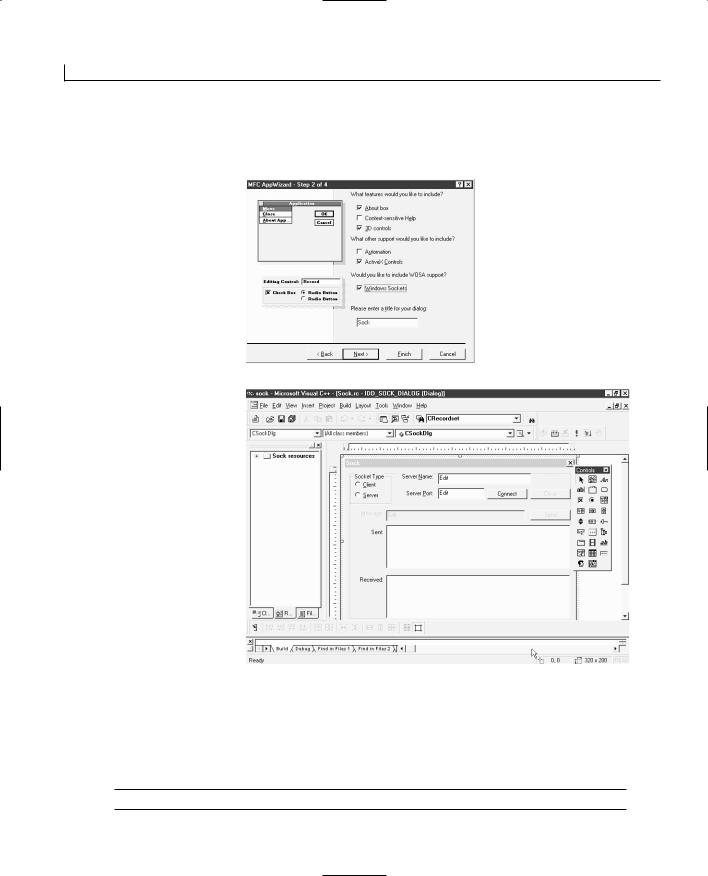
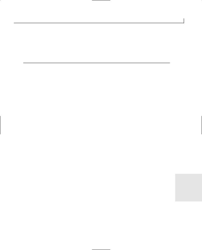

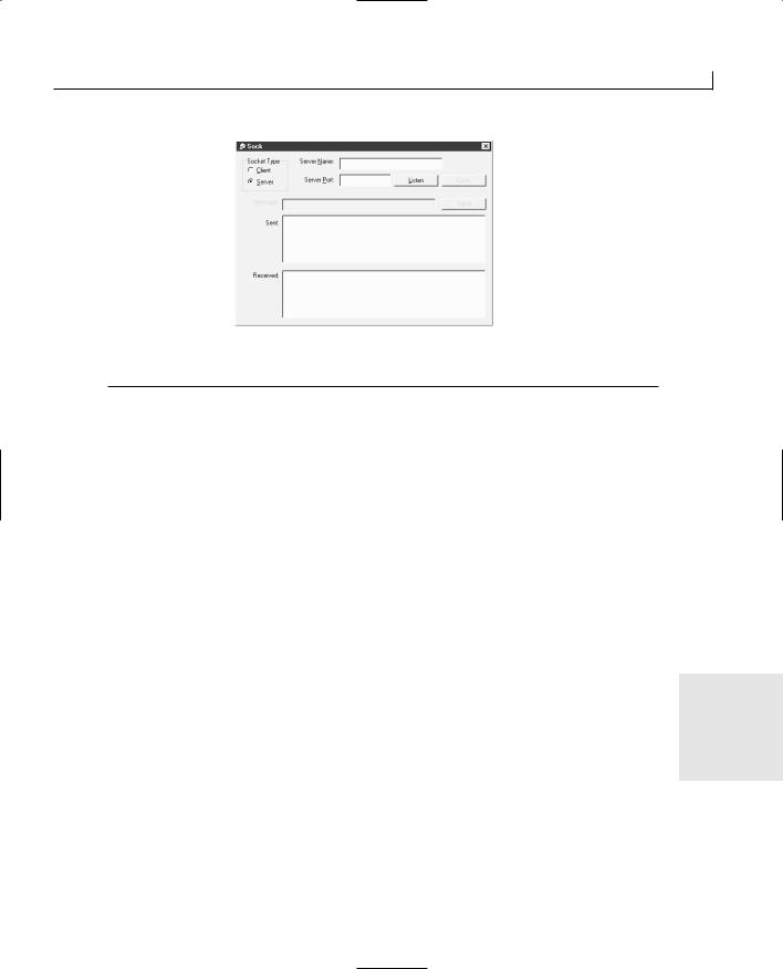
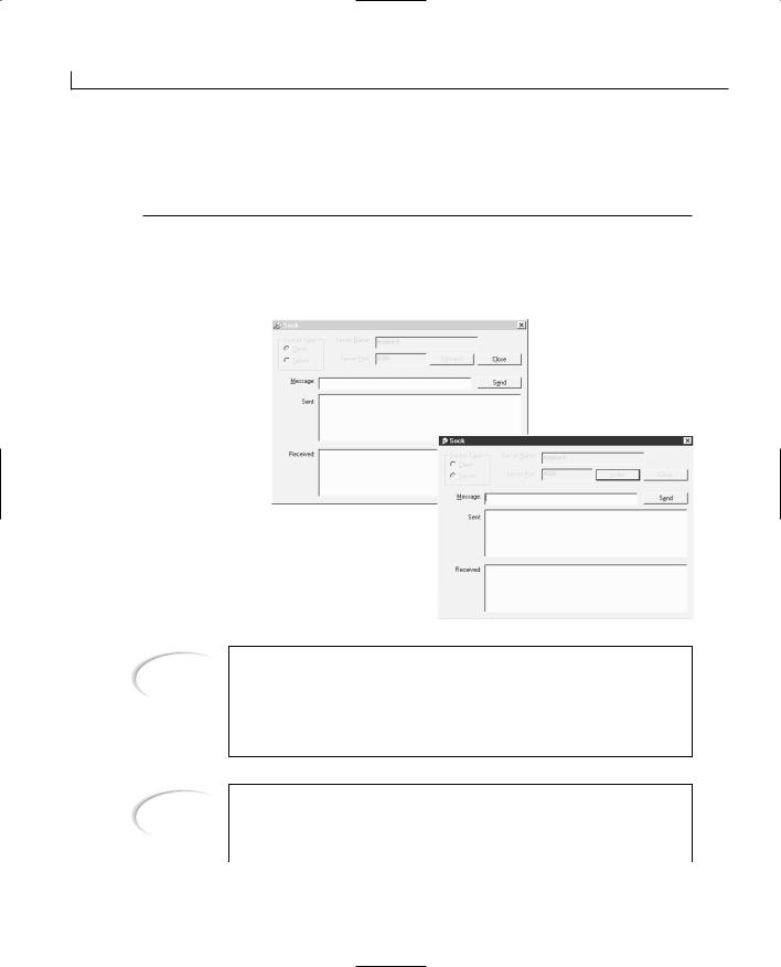

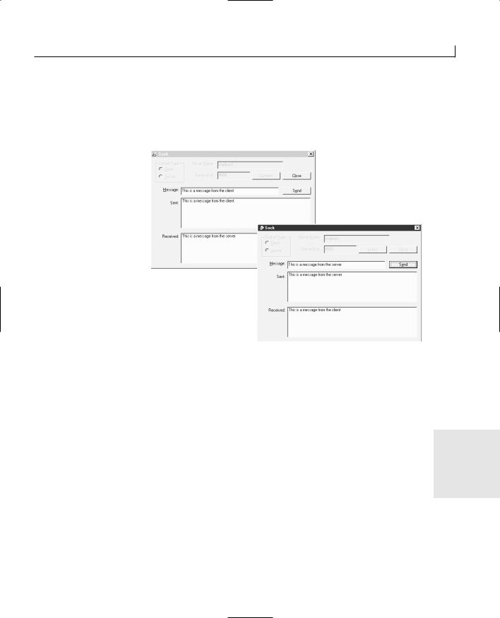
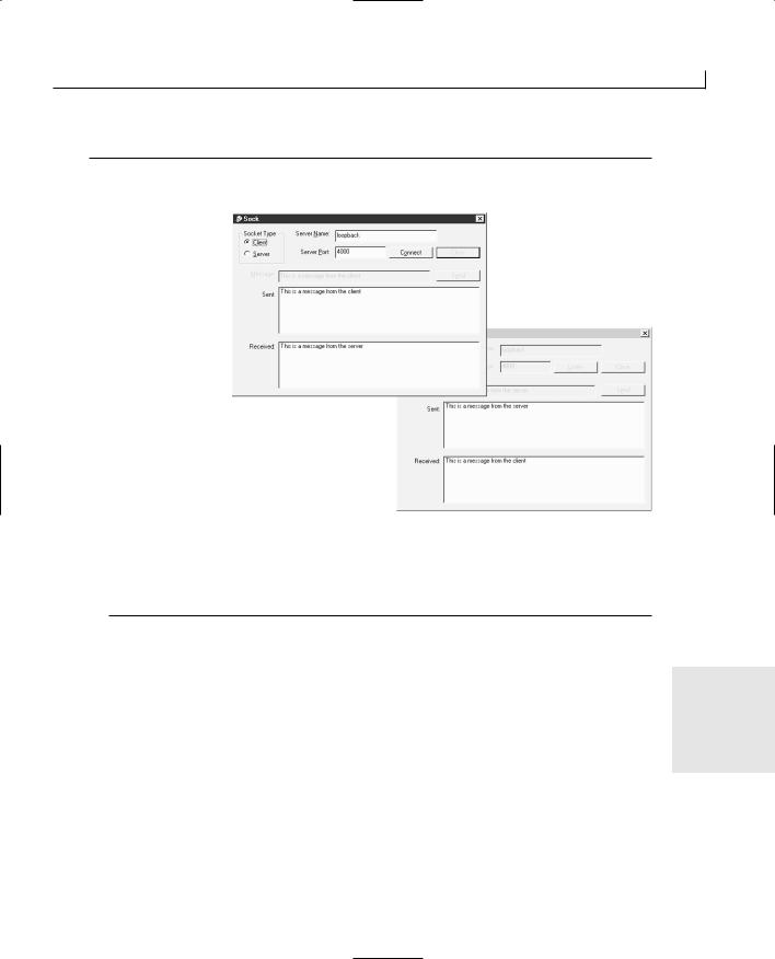

WEEK 3
DAY 21
Adding Web Browsing Functionality to Your Applications
When Microsoft made the decision a few years ago to make all its applications Internet-enabled, it wasn’t just talking about making Word read and write HTML pages. It wanted to make the Internet an integrated part of every application, in some way or another. Well, when it comes to development tools, making the editor double as an email client isn’t really a practical integration. However, making it easy for the users of development tools to build Internetenabled applications is a very practical feature. And this is exactly what Microsoft did.
One of the capabilities that Microsoft made available to its application development tools is using Internet Explorer as an integrated part of any application. This means that you can include Internet Explorer, and all its associated components, in your own applications. The possibilities extend far beyond

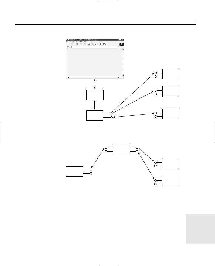

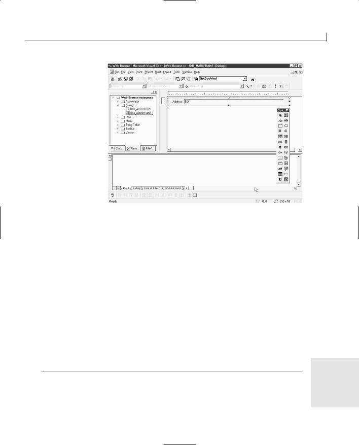
Adding Web Browsing Functionality to Your Applications |
529 |
FIGURE 21.5.
Browsing to a specified
URL.
Displaying the Current URL
When surfing the Web, you often follow links on Web pages that take you to other Web sites. When you do this, you wouldn’t know what Web site you accessed if your browser didn’t place the URL into the address box, indicating the site where you are and providing the opportunity to copy or modify the URL to find another page on the same site.
Getting the current URL from the browser is a simple matter of calling the GetLocationURL function and passing the result to the dialog bar. The problem is when to get the URL. It turns out that some event functions in the CHtmlView class can be overridden in your class. These functions will be triggered on various events that are triggered by the browser control. There are event functions for starting the navigation, beginning a download, monitoring a download’s progress, and, most important for our needs, indicating a download has finished. None of these event handler functions can be added to your view class through the Class Wizard. You have to add them all.
To add the download-complete event handler to your application, add a new member function to the view class of your application. Specify the function type as void, the function declaration as OnDocumentComplete(LPCTSTR lpszUrl), and the access as public. Edit the function, adding the code in Listing 21.3.
LISTING 21.3. THE CWebBrowseView OnDocumentComplete FUNCTION.
1: void CWebBrowseView::OnDocumentComplete(LPCTSTR lpszUrl)
2: { |
21 |
|
|
|
|
3: |
// Pass the new URL to the address bar |
|
4: |
((CMainFrame*)GetParentFrame())->SetAddress(lpszUrl); |
|
5: } |
|
|
|
|
|

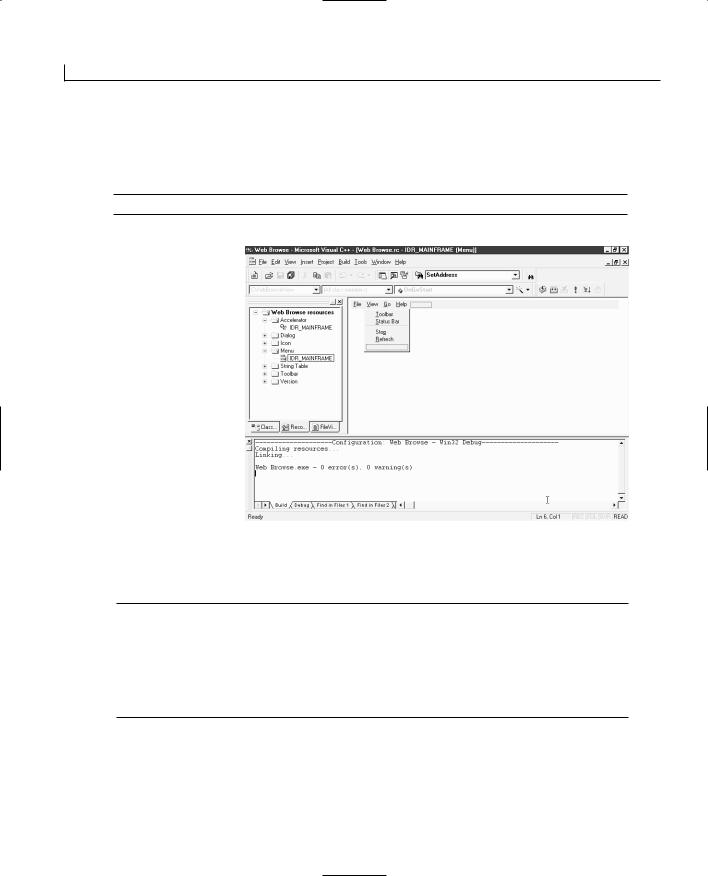
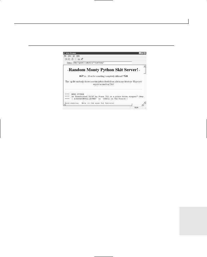
Adding Web Browsing Functionality to Your Applications |
535 |
6:Refresh();
7:}
FIGURE 21.7.
The Refresh function will perform a new download.
Now you can test this functionality by finding a Web site that returns a different page each time that you refresh the browser, such as the Random Monty Python Skit Server in Figure 21.7. As with the rest of the menu functions that you added to this application, this one should also be added to the toolbar.
Summary
Today you learn how Microsoft designed its Internet Explorer Web browser as a series of ActiveX components that could be used in other applications. You saw how Microsoft encapsulated the browser into the CHtmlView class, which can be used in SDI and MDI applications to provide Web browsing functionality to almost any application. You learned how you can use this view class to build a Web browser. You saw how you could use the dialog bar to place controls on a toolbar and how the events for these controls can be handled in the frame class for the application. Finally, you learned how to add menus to your application to call the various functions of the Web browser to provide a complete surfing experience.
Q&A
Q Why is Print Preview not included on the default menus when I choose |
21 |
CHtmlView as the base class for my view class? |
|
AThe printing for the CHtmlView class is performed by the browser, not the view class. You don’t have print preview because the browser doesn’t support it.

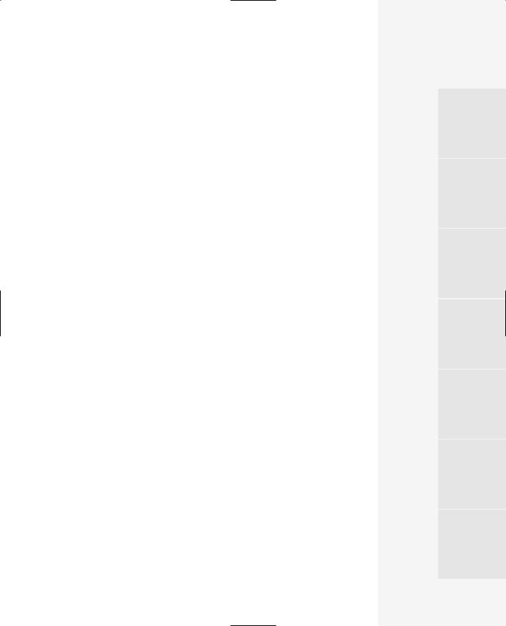


In Review |
539 |
An important thing that you learned was how you can enable your applications to perform more than one task at a time. This is an important piece of functionality, and more applications are requiring this capability every day. Not only did you learn how to make your applications perform multiple tasks at once, but you also learned two different ways to do so. First, you learned about the OnIdle function and how you can hook into this function to trigger your own functionality to be run when the application is sitting idle. You also learned about the shortcomings of using this approach to adding a second task to your application and how it can prevent your application from responding to the user. You need to slice the background task into little pieces that can be done quickly, which requires you to develop some elaborate way of keeping track of where the task is and where it needs to pick back up when the application is idle again.
The second way that you learned to give your applications a second or third task to do is by spinning off separate threads, which run completely independent of the main userinterface thread. You learned how to create a callback function that controls the top level of execution for the threads and how you can start and stop the thread as necessary.
You also saw how these independent threads are completely independent from the rest of the application and how they’ll continue to run, even when the rest of the application is also busy. If you feel the need to look at all this a second time, you might want to read Day 18 again.
Another area of growing importance that you learned about was how to build Internet applications using the Winsock interface classes. You learned how you can build one application that connects to another over a network and sends messages back and forth. You learned that, just like with a telephone, for one application to connect to another, the second application has to be listening for the connection. You saw how easy it is to send messages and to be notified when a message has arrived after the connection between the two applications has been made. If you need to review some of this, you might want to look back at Day 20.
Finally, you learned how you can incorporate the Microsoft Internet Explorer Web browser into your application without any effort whatsoever. You learned how you can control the browser by specifying the URL that it should load and display for the user and how you can display informational messages to the user to show what the browser is doing and when it’s busy. If you need to look back at this to refresh your memory, you can go back to Day 21.
That’s it. You’re done. You’ve covered a lot of ground and learned some advanced topics, especially over this last week. Now it’s time to put this book down and get busy programming, building your own applications using what you’ve learned. Good luck. If you find that you need a little help or advice, a good place to turn is the Microsoft newsgroups on the Internet. They are full of people who are both knowledgeable and helpful.

APPENDIX A
C++ Review
The appendix is designed to provide you with a quick review of the fundamentals of the C++ programming language. After reading this appendix, you will have a thorough understanding of the various aspects of C++ and its syntax.
Creating Your First Application
Your first example is a simple program that displays “Hello World” on the screen. For this, you create a workspace and the C++ file required for the program. The procedure for writing a C++ program using Visual C++ is simple and easy. Follow these steps:
1.From the main menu, select Visual C++.
2.Select File | New from the Visual C++ toolbar.
Make sure the Projects tab is selected (see Figure A.1).
3.Select Win32 Console Application from the options on the left.
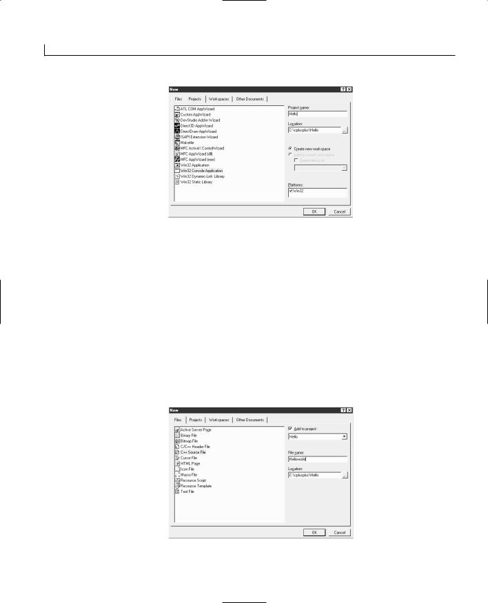

C++ Review |
543 |
The Helloworld.cpp file is where you add the C++ source code. All C++ source code files
have a .cpp extension. Later, I will cover other file types. |
A |
|
|
You create all the tutorial examples in this section in a similar way. The only difference |
|
is that the names of the workspaces and the files are different. |
|
Helloworld.cpp |
|
The Helloworld program displays HELLO WORLD on the screen. Listing A.1 contains the |
|
code. Type the code exactly as shown in the Helloworld.cpp window. Do not type the line |
|
numbers; they are for reference only. C++ is case sensitive, so main is not the same as |
|
MAIN, which is not the same as Main. |
|
LISTING A.1. Helloworld.cpp.
1:// Workspace Name: Hello
2:// Program Name: Helloworld.cpp
4:# include <iostream.h>
6:int main()
8:{
9:cout<< “HELLO WORLD \n”;
10:return 0;
11:}
To run the program, follow these steps:
1.Select File | Save to save your work.
2.Select Build | Set Active Configuration (see Figure A.3).
3.Highlight Hello - Win32 Debug and click OK (see Figure A.4).
4.Select Build | Build Hello.exe.
Visual C++ compiles and links the program to create an executable file. The configuration window indicates the success or failure of the compilation. A successful compilation returns
Hello.exe - 0 error(s), 0 warning(s)
If you encounter any errors, verify that all the lines of the program were typed exactly as shown.
To execute the Helloworld program, select Build | Execute Hello.exe.
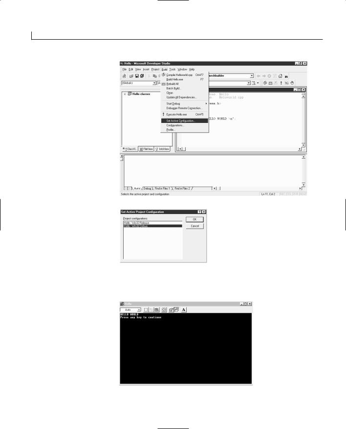


C++ Review |
547 |
writing a statement, and as mentioned before, all statements in C++ should end with
semicolons. A function prototype consists of a return type, name, and parameter list. The A return type in the main() function is int, the name is main, and the parameter list is (), null.
A function must have a prototype and a definition. The prototype and the definition of a function must agree in terms of return type, name, and parameter list. The only difference is that the prototype is a statement and must end with a semicolon. Listing A.2 illustrates this point with a simple program to calculate the area of a triangle.
LISTING A.2. Area.cpp.
1:// Workspace: Triangle
2:// Program name: Area.cpp
3:// The area of a triangle is half its base times height
4:// Area of triangle = (Base length of triangle * Height of triangle)/2
6: #include <iostream.h> |
// Precompiled header |
7: |
|
8: double base,height,area; |
// Declaring the variables |
9: double Area(double,double); |
// Function Prototype/declaration |
10: |
|
11:int main()
12:{
13:cout << “Enter Height of Triangle: “; // Enter a number
14: cin >> height; |
|
// Store the input in variable |
15: cout << “Enter Base of Triangle: “; // Enter a number |
||
16: cin >> base; |
// Store the input in variable |
|
17: |
|
|
18: area = Area(base,height); |
// Store the result from the Area |
|
function |
|
|
19: |
|
// in the variable area |
20: cout << “The Area of the Triangle is: “<< area << endl ; // Output the area 21:
22: return 0; |
|
23: } |
|
24: |
|
25: double Area (double base, double height) |
// Function definition |
26: { |
|
27: area = (0.5*base*height); |
|
28: return area; |
|
29: } |
|
|
|
This program declares three variables, base, height, and area, on line 8. Variables store values that are used by the program. The type of a variable specifies the values to be stored in the variable. Table A.1 shows the various types supported by C++.


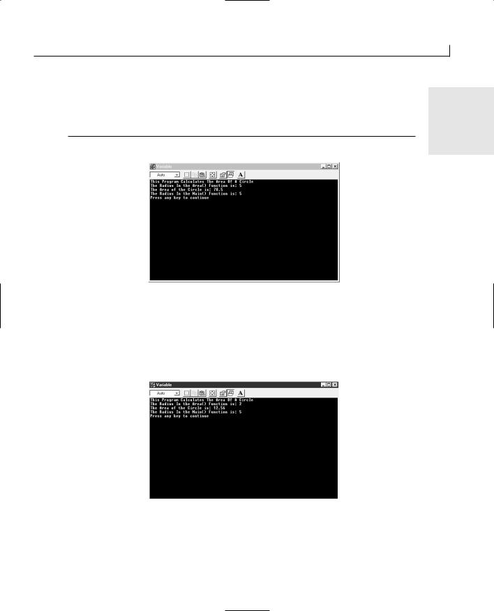


C++ Review |
561 |
On line 5, the struct keyword is followed by the name of the structure. The actual defini-
tion of the structure is enclosed in the curly brackets. This particular structure defines a A data member of type int and name pig_value. If you remember, I mentioned earlier that
when you define a structure, you basically define a custom-made data type. All data
FIGURE A.10.
Structure output.
types end with a semicolon, so the structure should also end with a semicolon. On line 12, you define three instances of the same type of farm_house, each of which contains a single int type variable.
On lines 14 through 16, you assign values to the member variables of each structure. The structure member operator (.), also called the dot operator, is used to access member variables of the structure. On lines 18 through 20, the assigned values are output to the screen. Figure A.10 shows the output from this program.
The most important concept of object-oriented programming is encapsulation. Encapsulation can involve one or more classes. Encapsulation promotes safeguards and data hiding. The struct.cpp program had no encapsulation or classes. What do encapsulation and classes mean in object-oriented programming?
Let’s start with describing the syntax and components of a class:
class class_name
{
public: class_name_constructor; ~class_name_destructor; class_method_prototypes(); class_member_variables; private: class_method_prototypes();


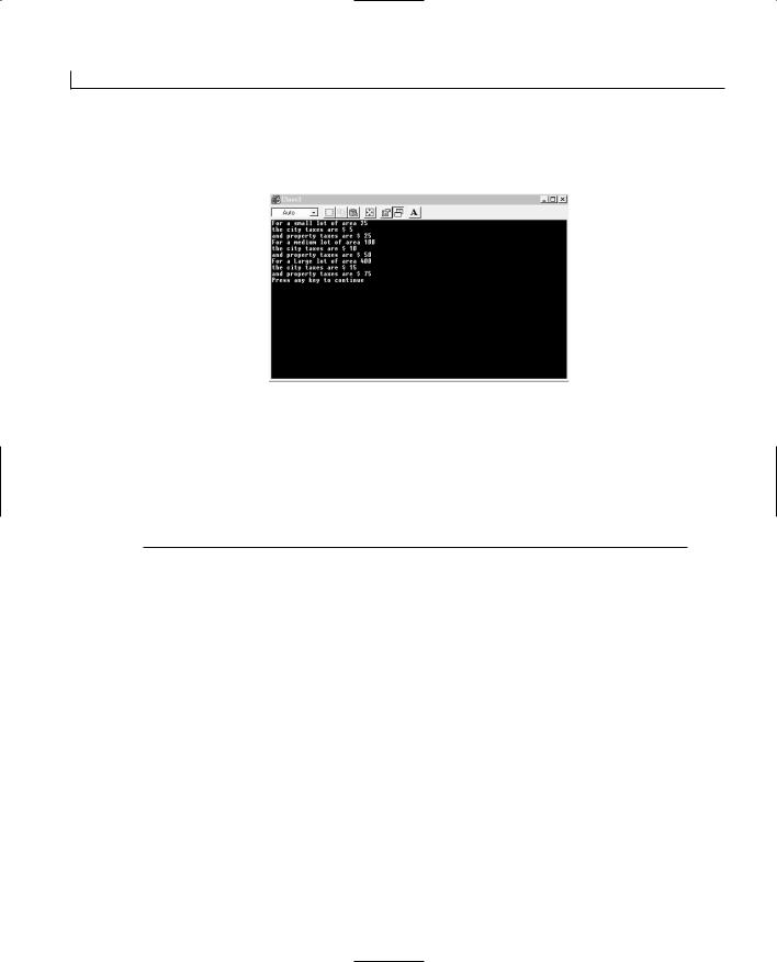

C++ Review |
569 |
Lines 17 through 29 declare the class Lot_size with its data members and methods. On
line 20, the class Tax_assessment is embedded in this class. The object taxes is also A declared on this line, and it is under the privacy of the class Lot_size. The only methods
that would be able to access this object are the ones belonging to the Lot_size class. The Lot_size class has four public methods declared and defined on line 22 and lines 26 through 28. Line 25 of the set() method has another set() method defined. This is not a recursive method but rather another example of function overloading. The set() method on line 10 and line 22 differ in the number of parameters. The set() method on line 25 can access the object taxes because it is defined under the class Tax_assessment on line 20.
The main() function begins on line 32 and has a return type int. On line 34, the objects of class Lot_size are declared. On lines 36 through line 38, the values of the objects are set using the set() method. An important point to note is that the class Tax_assessment has no objects in the main() method, so you cannot access any data member or method of this class from main().
On line 41, the area of the Lot_size is output by operating the get_area() method on an object of class Lot_size. On line 42, the city taxes are output by operating the method get_data2 on an object of Lot_size. This approach is required because the city_tax is a member data of class Tax_assessment, which cannot be operated on directly in the main() method. You use the method get_data2, which is a method of Lot_size and has access to the object taxes, which in turn can be accessed via get_city_tax.
Inheritance
One of the advantages of programming in C++ or any other object-oriented language is taking a global to local approach. Suppose you need to develop a program that comprehends all metals and their characteristics. If you take the class approach of the previous section, you would probably have one class named metals. The data members of metals would probably be density and volume. You could have another class named gold and one for aluminum. The data members describing gold and aluminum would need all the properties of metals in addition to their own data members such as color and shine. If you could devise a hierarchy of classes such that the classes for gold and aluminum would have only their individual data members but inherit the generic properties from the parent metals class—then you would be using inheritance.
Inheritance is also called derivation. The new class inherits the functionality of an exist-


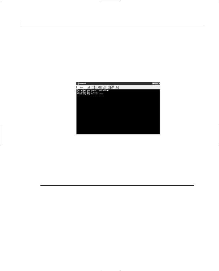


APPENDIX B
Answers
This appendix provides the answers to the quiz questions and exercises at the end of each chapter.
Day 1
Quiz
1.How do you change the caption on a button?
In the window layout editor, select the button to be changed. Right-click the mouse and select Properties from the pop-up menu. Change the value in the Caption field.
2.What can you do with the Visual C++ AppWizard?
You can use it to build a shell for your application, based on the type of application and the functionality needs of the application. The shell will have support for the desired functionality already built in.


Answers |
585 |
Day 3
Quiz
1. What are the possible mouse messages that you can add functions for?
WM_LBUTTONDOWN, WM_LBUTTONUP, WM_LBUTTONDBLCLK, WM_RBUTTONDOWN,
W M
_RBUTTONUP, WM_RBUTTONDBLCLK, WM_MOUSEMOVE, and WM_MOUSEWHEEL. |
B |
|
2.How can you tell if the left mouse button is down on the WM_MOUSEMOVE event message?
You can mask the flags passed to the OnMouseMove function with the MK_LBUTTON flag, as follows:
((nFlags & MK_LBUTTON) == MK_LBUTTON)
3.How can you prevent the cursor from changing back to the default cursor after you set it to a different one?
Return TRUE in the OnSetCursor event function, preventing the ancestor OnSetCursor function from being called.
Exercises
1.Modify your drawing program so that the left mouse button can draw in red and the right mouse button can draw in blue.
Add a function for the WM_RBUTTONDOWN event message and write the code for it as in Listing B.4.
LISTING B.4. MOUSEDLG.CPP—THE OnRButtonDown FUNCTION.
1:void CMouseDlg::OnRButtonDown(UINT nFlags, CPoint point)
2:{
3:// TODO: Add your message handler code here and/or call default
5:///////////////////////
6:// MY CODE STARTS HERE
7:///////////////////////
9:// Set the current point as the starting point
10:m_iPrevX = point.x;
11:m_iPrevY = point.y;
13:///////////////////////
14:// MY CODE ENDS HERE
15:///////////////////////
17:CDialog::OnRButtonDown(nFlags, point);
18:}


Answers |
597 |
Follow these steps:
1.Using the Class Wizard, add a function for the WM_CONTEXTMENU event message in your dialog window.
2.Edit the function, adding the following code:
void CMenusDlg::OnContextMenu(CWnd* pWnd, CPoint point)
{
// TODO: Add your message handler code here and/or call default
B
///////////////////////
//MY CODE STARTS HERE
///////////////////////
//Declare local variables
CMenu *m_lMenu; |
// A pointer to the menu |
CPoint m_pPoint; |
// A copy of the mouse position |
//Copy the mouse position to a local variable m_pPoint = point;
//Convert the position to a screen position ClientToScreen(&m_pPoint);
//Get a pointer to the window menu
m_lMenu - GetMenu();
//Get a pointer to the first submenu m_lMenu = m_lMenu->GetSubMenu(1);
//Show the Pop-up Menu
m_lMenu->TrackPopupMenu(TPM_CENTERALIGN + TPM_LEFTBUTTON,
m_pPoint.x, m_pPoint.y, this, NULL);
///////////////////////
// MY CODE ENDS HERE
///////////////////////
CDialog::OnRButtonDown(nFlags, point);
}
Day 7
Quiz
1.How can you specify that the text is to be underlined?
Pass 1 as the value for the bUnderline argument to the CreateFont function.
2.How can you print your text upside down?
Pass 1800 as the nEscapement argument to the CreateFont function.
3.How many times is the EnumFontFamProc callback function called by the operating


Answers |
615 |
3.How can you remove the Num Lock status indicator from the status bar? Remove the ID_INDICATOR_NUM from the indicators table near the top of the main frame source code file.
4.Why do you have to edit the resource file to add a combo box to a toolbar?
You need to add a separator to the toolbar as a placeholder in the toolbar. The toolbar designer will do its best to prevent you from adding the separators, assuming
that they are a mistake. |
B |
|
Exercises
1.Add another pane to the status bar to display the current width selected.
Add an entry to the strings table with an ID of ID_INDICATOR_WIDTH and a caption of VERY THICK.
Add another entry to the status bar indicators table at the beginning of
CMainFrame.cpp: |
|
static UINT indicators[] = |
|
{ |
|
ID_SEPARATOR, |
// status line indicator |
ID_INDICATOR_WIDTH, |
|
ID_INDICATOR_COLOR, |
|
ID_INDICATOR_CAPS, |
|
ID_INDICATOR_NUM, |
|
ID_INDICATOR_SCRL, |
|
}; |
|
Add a new member function to the CToolbarDoc class. Specify the function type as afx_msg void, the function definition as OnUpdateIndicatorWidth (CCmdUI *pCmdUI), and the access as protected. Edit the function as follows:
void CToolbarDoc::OnUpdateIndicatorWidth(CCmdUI *pCmdUI)
{
CString strWidth;
// What is the current width? switch (m_nWidth)
{
case 0: // Very Thin strWidth = “VERY THIN”; break;
case 1: // Thin strWidth = “THIN”; break;
case 2: // Medium strWidth = “MEDIUM”; break;
case 3: // Thick strWidth = “THICK”; break;


Answers |
627 |
After generating the project skeleton, copy the line source code and header files into the project directory. Add these files into the project.
Edit the CLine class declaration, adding the AFX_EXT_CLASS macro to the class declaration.
Compile the DLL. Copy the DLL into the debug directory for the test application.
Open the regular DLL project. Delete the line source code and header files from
the project in the File View of the workspace pane. Add the line DLL LIB file to B the project. Edit the drawing functionality source-code file, changing the line class
header include to include the version in the CLine DLL project directory, as in Listing B.30.
LISTING B.30. THE CModArt INCLUDES.
1:// ModArt.cpp: implementation of the CModArt class.
2://
3://///////////////////////////////////////////////////////////////////
5:#include <stdlib.h>
6:#include <time.h>
8:#include “stdafx.h”
9:#include “..\LineDll\Line.h”
10:#include “ModArt.h”
Compile the project. Copy the DLL into the test application project debug directory.
Run the test application.
2.Alter the line class DLL so that it uses a consistent line width for all lines.
Open the line class DLL project that you created in the previous exercise. Edit the class constructor, replacing the initialization of the m_nWidth variable with a constant value, as in Listing B.31.
LISTING B.31. THE CLine CONSTRUCTOR.
1:CLine::CLine(CPoint ptFrom, CPoint ptTo, UINT nWidth, COLORREF crColor)
2:{
3:m_ptFrom = ptFrom;
4:m_ptTo = ptTo;
5:m_nWidth = 1;
6:m_crColor = crColor;
7:}


Answers |
631 |
29:break;
30:}
31:// Start the thread, passing a pointer to the spinner
32:m_pSpinThread[nIndex] = AfxBeginThread(ThreadFunc,
33:(LPVOID)&m_cSpin[iSpnr], iPriority);
34:}
35:}
B
Day 19
Quiz
1.What are the three aspects of a control that are visible to the container application? Properties, methods, and events.
2.Why do you need to design a property page for your control?
To provide the user with the ability to set the properties of the control.
3.What are the four types of properties that a control might have? Ambient, extended, stock, and custom.
4.What happens to the parameters that are passed to the methods of a control? They are marshaled into a standardized, machine-independent structure.
5.What tool can you use to test your controls? The ActiveX Control Test Container.
Exercises
1.Add a method to your control to enable the container application to trigger the generation of a new squiggle drawing.
Open the Class Wizard to the Automation tab. Click the Add Method button. Enter a method name, such as GenNewDrawing, and specify the return type as void. Click OK to add the method. Edit the method, adding the code in Listing B.34.
LISTING B.34. THE CSquiggleCtrl GenNewDrawing FUNCTION.
1:void CSquiggleCtrl:: GenNewDrawing()
2:{
3:// TODO: Add your specialized code here and/or call the base class
4:// Set the flag so a new drawing will be generated
5:m_bGenNewDrawing = TRUE;
6:// Invalidate the control to trigger the OnDraw function
7:Invalidate();
8:}


APPENDIX C
Printing and Print
Previewing
by Jon Bates
Using the Framework’s Functionality
The SDI and MDI frameworks created by the AppWizard add the hooks for printing and previewing by default. These can be turned off by unchecking the Printing and Print Preview option in Step 4 of the MFC AppWizard, but generally they are useful to include in any project and add very little overhead. Most of the real work of printing is taken care of by the device context and GDI. The framework presents you with a device context for a print document page; you can treat it pretty much as if it’s a normal window device context.

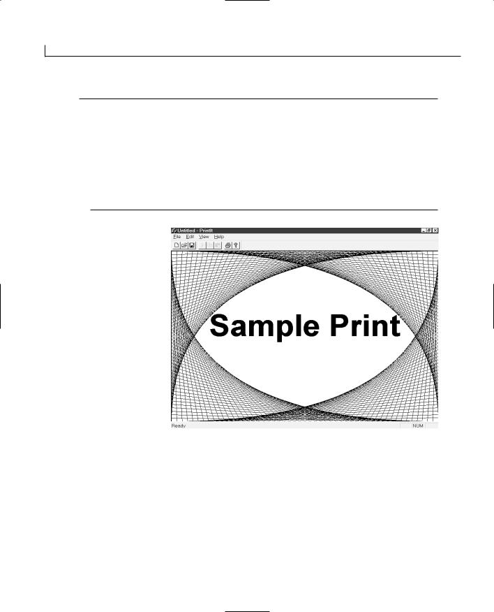
Printing and Print Previewing |
641 |
If you build and run the program after adding these lines to the OnDraw() function of Listing C.1, you should see a graphical display in your application window, as shown in Figure C.1.
So the big question is this: What must you do to print this image output? Surprisingly little—because the standard framework tries to print this by calling your OnDraw() function and passing the device context for the printer rather than for the window.
If you click the File menu of the PrintIt application and choose Print Preview, you’ll see a small representation of the image in the top-left corner, although the font is too big for the line drawing. This isn’t the framework’s fault; it has done its best to represent your window, but it was passed the wrong coordinates for the device context. The problem lies with the GetClientRect()used in line 23.
Notice that GetClientRect() is a member of the view, not of the device context. This C works fine for the window because the device context is the same size as the window
rectangle. Now you’re passing the window rectangle to the printer device context (which is small in comparison) but creating a 2.2cm high font that is always the same size (because of the mapping mode).
Overriding OnPrint()
To fix the client rectangle coordinate size problem, you must pass the correct rectangle for the printer rather than the window. Fortunately, the framework calls a virtual function that you can override in your view and use to find all the information you need. As you read earlier, this function is named OnPrint() and is analogous to OnDraw(). When drawing in a window, OnDraw() is called; when drawing on a printer, OnPrint() is called. You might be wondering how the drawing code in OnDraw() was executed to print preview the sample graphical display. The default CView implementation of OnPrint() simply calls OnDraw(), passing its printer device context.
Your OnPrint() doesn’t have to call OnDraw(); you can override OnPrint() to make it draw something entirely different, but many applications must print out what the user sees. These applications reuse their OnDraw() code with the printer device context.
To override the OnPrint() virtual function, perform the following steps:
1.Click the ClassView tab of the Project Workspace view.
2.Click the top plus sign to open the view of the project classes.
3.Right-click the view class to which you want to add the OnPrint() override (such as CPrintItView in the PrintIt example) to display the context menu.
4.Select the Add Virtual Function option to display the New Virtual Override dialog box.


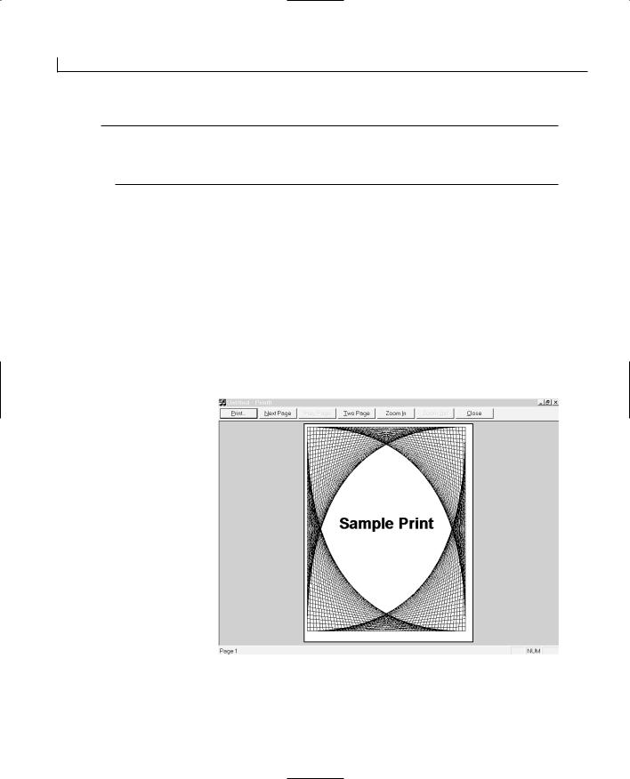

Printing and Print Previewing |
647 |
window height to the paper height. You can find these ratios as shown in lines 9 and 13 by dividing the paper dimensions by the window dimensions.
The next thing you must calculate is the device’s own aspect ratio peculiarities. You can use the GetDeviceCaps() function in line 17 to find the ratio of width to height in the device itself and store the result in dAspect.
Using these values, you can now calculate the device’s comparative width and height coordinates in terms of the opposing window dimension, as shown in lines 21 and 25. This calculation, which includes the device aspect ratio for each dimension, will yield the adjusted height for the full page width or vice versa. Now you must decide whether you can best fit the full width or height of a page and adjust the other dimension. The condition on line 32 makes this decision based on the bigger width or height. This means that if you have a tall, thin window, it is better to use the full height of the paper and adjust
the width; conversely, if you have a short, wide window, it is better to use the full width C and adjust the height. Depending on what is better, the adjustment is made on line 35 or
42 by setting the bottom-right point’s x- or y-coordinate to the adjusted width or height.
Notice that all the other dimensions are set to rcClient from the paper in the assignment on line 29, so the adjustment is the only change required. After this section, the program continues and will use the adjusted rectangle to do its drawing.
If you build and run the application after adding the lines in Listing C.3 to the OnDraw() function, you should see that printing or previewing the window will now maintain the same aspect ratio as the onscreen window. If you stretch the window to make it higher than it is wide, the printed output will use the full height of the page rather than the full width, but still maintain the correct aspect ratios.
Pagination and Orientation
Printing a single page to represent the view in a window is a common requirement, but largely the printing process is concerned with printing large and complex multipage documents from the user’s sophisticated data. The framework comes to the rescue again and simplifies this process by providing a common Print Setup dialog box and a page enumeration system to print and preview the specified range of pages.
Setting the Start and End Pages
The first considerations for a multipage document are the start and end pages, which also indicate how many pages you are going to print. A framework virtual function in the view class is called first when printing begins. This function is OnPreparePrinting() and it supplies one parameter, the CPrintInfo object pInfo. This is the first time you’ll see the


Printing and Print Previewing |
651 |
FIGURE C.3.
The Print Preview output of a multipage document.
C
FIGURE C.4.
The standard Print dialog box.
THE Collate CHECK BOX
If the user unchecks the Collate check box on the Print dialog box, the printer driver will automatically repeat the same pages together. You don’t need to do anything special in your code to handle this—but the feature must be supported by the printer driver; otherwise it will be disabled and inaccessible in the Print dialog box.


Printing and Print Previewing |
657 |
Aborting the Print Job
Another use of OnPrepareDC() is to call printer escapes or other print document–specific functions. If you had a particularly long report, you might want to give the user the option of terminating the printing process and aborting the print. The AbortDoc() device context function aborts the printing document for a printer device context. You can try this by adding the following lines to OnPrepareDC() and aborting the document after three pages:
if (pDC->IsPrinting())
if (pInfo->m_nCurPage==3) pDC->AbortDoc();
Direct Printing Without the Framework
So far in this chapter, I’ve shown you the SDI and MDI framework support for printing. C This support melds nicely into the Document/View architecture, but there are times when
you just want quick and easy access to a printer or don’t have the framework available— in a dialog-based application, for example.
The framework support hides lower-level printing support that is the bedrock for all the printing operations. This section explains how this support works and shows it in use in a dialog box-based application example.
Invoking the Print Dialog Box Directly
You saw in the earlier section “Using the Print Dialog Box” how the CPrintDialog
class provides a wrapper for the common PRINTDLG dialog and how this was called from
CView::DoPreparePrinting().
The same dialog box and class can be used directly to set up the destination printer and its default settings just like you’d use a normal modal dialog box. You can use the same access functions to set the page numbers and copy defaults as you used from inside the framework’s DoPreparePrinting() function.
Listing C.7 shows this dialog box being used directly to configure the printer for dialog box-based printing and then prints a small document from the defaults set by the dialog box.
The direct printing mechanism works via the StartDoc() and EndDoc() functions shown in this listing and is explained in the next section.
You can use the AppWizard to create a dialog box-based application named DlgPrint and create an OnOK() handler with the ClassWizard to implement the printing code, as shown in Listing C.7.


Printing and Print Previewing |
659 |
Listing C.7 declares a CPrintDialog object dlgPrint at line 6 that takes three parameters in its constructor. The first parameter is a flag that can be set as TRUE to display the Print Setup dialog box, or FALSE to display the Print dialog box. The second parameter is a set of combinable flags that customize the settings of the dialog box (too numerous to cover here). The third parameter is a pointer to the parent window; in this case the C++ this pointer indicates that the dialog box is the parent.
On line 8, dlgPrint.DoModal()is called to display this dialog box. If the user clicks OK, the print begins; otherwise, the block is skipped.
When the user has clicked OK in the Print dialog box, a device context for the printer is |
|
|
created and attached to a CDC object in line 13 to make it easier to use. You must remem- |
|
|
ber to delete the device context itself, as shown in line 40. |
|
|
C |
||
You can add the listing lines and handler, build and run it, and click OK of the dialog |
||
box application to run the new code. |
|
|
Using StartDoc() and EndDoc() |
|
|
The CDC device context has many printer-specific functions. To start a new print, |
|
|
|
||
Windows must create a spool document to store the print job and submit it to the printer |
|
|
when it is complete. The StartDoc() function tells Windows to start spooling, and the |
|
|
EndDoc() function tells it that the document is complete and can be sent to the printer. |
|
|
You saw the AbortDoc() function earlier that will abort the print and cancel the print job |
|
|
rather than send to the printer. |
|
|
Listing C.7 calls the StartDoc() member of the printer device context object dcPrint at |
|
|
line 24, passing a pointer to a DOCINFO structure. This structure holds the details of the |
|
|
print job. The only detail you must specify is a name for the spool document, which is |
|
|
assigned at line 18. Notice that it has an unusual cbSize member that holds the size of the |
|
|
structure. This is assigned the value from sizeof(myPrintJob) at line 17. You see this sort |
|
|
of strange action going on a lot at the Win32 API level because DOCINFO is an old C-style |
|
|
structure; the cbSize is used because there are a few different forms of DOCINFO and the |
|
|
only way to tell them apart is the size. |
|
|
When StartDoc() is called, it will try to start the print job and return a positive value |
|
|
if it succeeds. There are many reasons why it might fail, such as low disk space or |
|
|
memory, or a corrupt printer driver, so it’s a good idea to carry on with the print only |
|
|
after checking the return code. |
|
|
After the document is printed, you should call EndDoc() as shown on line 36 to start |
|
|
printing the document. |
|
APPENDIX D
Understanding and
Exception Handling
by Jon Bates
Using Exceptions
An exception is an object that holds details about something that has gone wrong. The clever thing about exception handling is that you can create an exception when something goes wrong in a low-level function and have it automatically bubble back up to a calling function that can deal with all such exceptions in one place.
Running Code and Catching the Errors
The system automatically detects certain error conditions and generates exceptions for them. If you don’t deal with them in your application, they will bubble back out of your code and be handled by Windows’s own exception-catching mechanisms. If you want to see this in action, just add the following two lines to any of your code and run it:
CDC* pNullDC = 0; pNullDC->SetPixel(0,0,0);
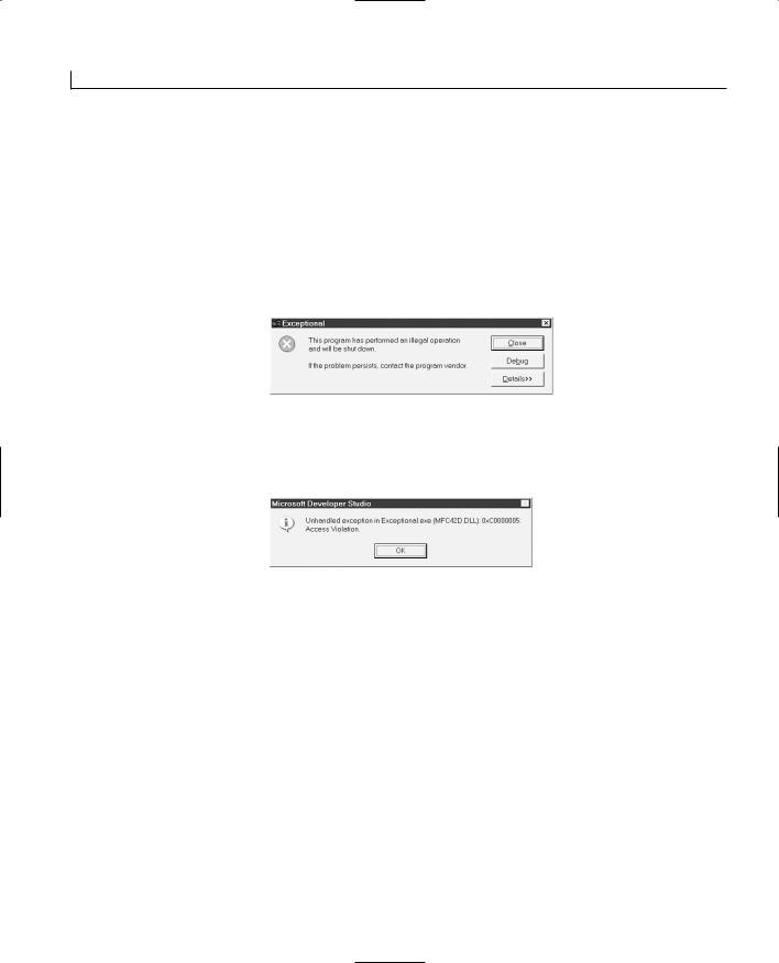
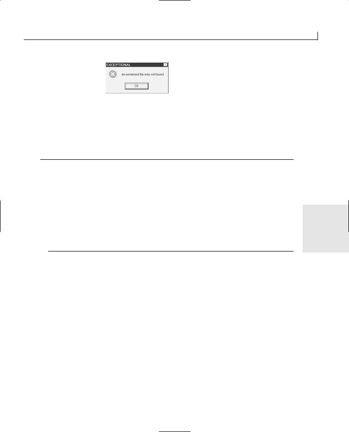

Understanding and Exception Handling |
665 |
17: }
18: catch(CResourceException* e)// Catch Resource Exceptions
19: {
20: // ** Report the Resource exception error
21: AfxMessageBox(“Oops, duplicate resource name”); 22: e->Delete();
23: }
In Listing D.3, the memory file is automatically created in line 4, so line 5 won’t cause a file exception. However, naming two different system resources (a mutex and a semaphore) with the same name does cause a CResourceException in line 10 that is then caught by the second catch block in line 18, which displays the message box in line 21. If you try this code yourself, remember to add an #include <afxmt.h> line for the CMutex and CSemaphore definitions.
If you want to do a blanket exception catch, you don’t need to have a catch block for each type of exception; instead, you can catch the CException base class exception from which all the other more specific exception classes are derived (see Listing D.4).
LISTING D.4. LST29_4.CPP—USING THE catch BLOCK TO CATCH ALL TYPES OF EXCEPTIONS. |
D |
|
|
|
|
1:// ** Try a block of code
2:try
3:{
4:// ** Lots of code ...
5:}
6:catch(CException* e)
7:{
8:// ** General Error message, details in e
9:AfxMessageBox(“Oops, something went wrong!”);
10:e->Delete();
11:}
Notice that on line 6 the CException base class is used rather than a specific exception such as CFileException or CResourceException. You can test which type of exception was raised using the IsKindOf() function inside the catch block. For example, to test whether a file exception has been raised, you might use the following lines:
if (e->IsKindOf(RUNTIME_CLASS(CFileException))) AfxMessageBox(“File Exception”);
Because exceptions are derived from CObject, they support the MFC runtime class information. By using DECLARE_DYNAMIC and IMPLEMENT_DYNAMIC, the class informa-
Understanding and Exception Handling |
667 |
11:return TRUE;
12:}
13:
14: BOOL bSomeThingWentWrong = TRUE; 15:
16:void CExceptionalDlg::DoSomeFileHandling()
17:{
18:// ** ... File handling functions
19:if (bSomeThingWentWrong == TRUE)
20:{
21:CFileException* pException =
22:new CFileException(CFileException::generic);
23:throw(pException);
24:}
25:
26:// ** ... Yet More file handling
27:}
In Listing D.5 the try block encloses a call to the DoSomeFileHandling() function in line 16. This function may implement some file-handling procedures and raises an exception when the error condition on line 19 is found to be TRUE. Line 22 creates a new
CFileException object passing the CFileException::generic flag to its constructor and then D throws the new object in line 23 to be caught by the catch section in line 5.
This process of newing a CException-derived object and then using the throw keyword is the basis of the exception-raising mechanism. The specific details indicating the cause of the error can be attached to the CException object, or extra information can be added by deriving a class from the CException base class and adding extra variables to store more specific information.
Your catch block can then determine whether the error is too severe to be handled at that level. If so, you might want to throw the exception out to a higher-level enclosing catch block. You can use the throw keyword (with no parameters) from within the catch block to rethrow the exception before you delete it. Instead of deleting the exception, you could rethrow it to a higher level catch block by changing the catch block shown in Listing D.5 to add the throw keyword like this:
e->ReportError(); throw;
Then after reporting the error, the exception will be thrown again for an enclosing try block to catch. If you haven’t implemented this nesting, the overall MFC outside the catch block will catch it. You can use this nesting mechanism to determine the error severity and implement appropriate recovery mechanisms at various hierarchical levels in your program.


Understanding and Exception Handling |
673 |
was successful. The m_nAfxDaoError member holds one of the DAO-specific values from Table D.3. The m_pErrorInfo is a pointer to a CDaoErrorInfo structure that holds an error code, descriptive error strings, and a help context ID that is defined like this:
struct CDaoErrorInfo
{
long m_lErrorCode; CString m_strSource; CString m_strDescription; CString m_strHelpFile; long m_lHelpContext;
}; |
|
By interrogating this structure, you can find most of the specific database error details |
|
pertaining to the DAO exception. |
|
DAO exceptions can describe more than one error at a time, so you can use the |
|
GetErrorCount() member function to find out how many are being referenced. These other |
|
errors can then be obtained by passing the GetErrorInfo() function a zero-based index to |
|
the specific error. After calling GetErrorInfo() with a specific index in the range returned |
|
by the GetErrorCount() function, m_pErrorInfo will be updated to |
|
point to the specified object, and thus you can retrieve those values. |
D |
|
Using OLE Exceptions
There are two types of OLE exceptions, represented by two classes: the COleException class, which is normally used for server-side or OLE-specific operations, and the COleDispatchException class, which is used when dealing with client-side IDispatch-based operations such as calling ActiveX object functions.
The simpler of the two is the COleException class, which can be generated by calling the
AfxThrowOleException() function passing an OLE SCODE value. An OLE SCODE
is a 32-bit error code that is used to represent any kind of error arising from an OLE function.
This value would probably arise from the return code of a function call to a function on one of the interfaces of an OLE object. This SCODE value will then be stored in the exception’s m_sc member for analysis from within a catch block.
There is also a Process() static member function that is passed an exception object and will turn that exception into an SCODE value to represent that exception.
The COleDispatchException class is used in conjunction with OLE IDispatch interfaces and is thrown by the AfxThrowOleDispatchException() function. This function has two forms,

Understanding and Exception Handling |
675 |
tion class that extends the normal functionality by adding a m_strMessage CString variable to the exception, enabling you to specify your own message when constructing the exception.
LISTING D.6. LST29_6.CPP—CLASS DEFINITION FOR CCustomException IMPLEMENTED IN
CustomException.h.
1:// ** CustomException.h
2:// ** Header file for CCustomException
4:class CCustomException : public CException
5:{
6: |
DECLARE_DYNAMIC(CCustomException); |
7: |
|
8:public:
9:CCustomException(CString strMessage);
11:CString m_strMessage;
12:};
In Listing D.6 the class is implemented in its own CustomException.h header file and
derives from CException in line 4. The DECLARE_DYNAMIC macro in line 6 supplies the D MFC CObject-derived runtime class information required for you to decide the exception
type in a catch-all catch block. The constructor definition in line 9 takes a CString strMessage parameter to let you create the custom exception with the message that will be stored in the m_strMessage CString variable declared in line 11.
The corresponding CCustomException class implementation is shown in Listing D.7.
LISTING D.7. LST29_7.CPP—IMPLEMENTATION OF THE CCustomException CLASS.
1:// ** CustomException.cpp
2:// ** Implementation for CCustomException exception
4:#include “stdafx.h”
5: #include “CustomException.h” 6:
7: IMPLEMENT_DYNAMIC(CCustomException,CException); 8:
9:CCustomException::CCustomException(CString strMessage)
10:: m_strMessage(strMessage)
11:{
12:}
In Listing D.7 the usual header files are included, and the IMPLEMENT_DYNAMIC macro is used in line 7 to implement the MFC runtime class information functions. The constructor in line 9 takes the strMessage parameters and initializes the m_strMessage member

APPENDIX E
Using the Debugger and
Profiler
by Jon Bates
Creating Debugging and Browse
Information
A large part of application development is actually debugging your program. All software development is a tight cycle of application design, implementation, and debugging.
Visual C++ has an extensive debugging environment and a range of debugging tools that really help with program development. You can quickly identify problems, watch the contents of variables, and follow the flow of programs through your own code and the MFC code.
Tools such as the Spy++ program can show you the messages passed between Windows and your application and let you spy on applications to see which user interface controls and Window styles they use.
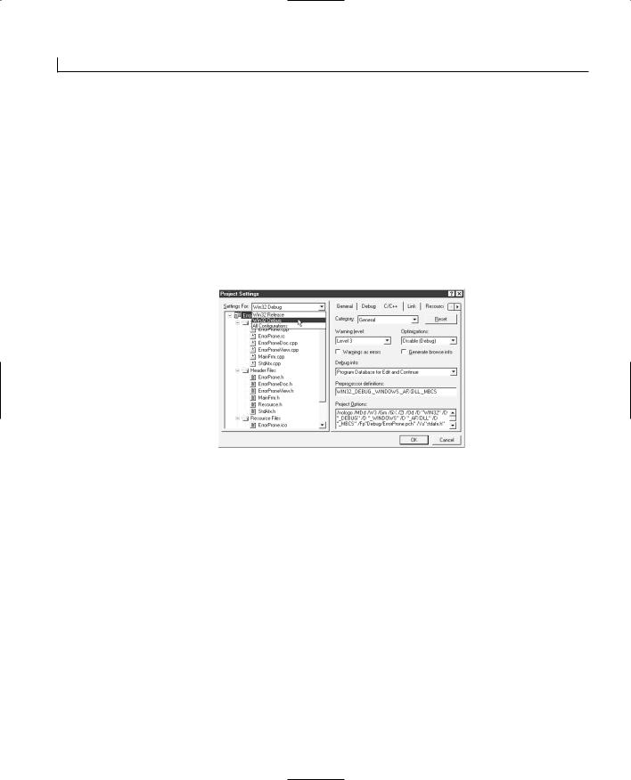
Using the Debugger and Profiler |
679 |
RELEASE MODE TESTING
You should always fully test your application after rebuilding it in Release mode before sending it to users. Bugs can arise from things such as leaving proper program code in ASSERT macros (discussed later this chapter), which are then removed, or because of the effect of some speed and memory optimizations.
Setting Debug Options and Levels
You can set a variety of debugging options and levels from the C/C++ tab of the Project Settings dialog box. This dialog page is available from the Project menu by selecting the Settings option (or by pressing Alt+F7) and then selecting the C/C++ tab.
With the General Category selected, the following items are available:
●Warning Level. This is the level of compiler warning messages given during compilation. You can set it to any of the values shown in Table E.1. The default level is Level 3, which is quite sensitive, although many good C++ programmers insist on using Level 4 to get the most warning of potential problems from the compiler.
Level 1 and no warnings (None) should be used only in special circumstances because they indicate only severe warnings (or none at all).
LEVEL 4 WARNINGS |
|
At level 4, you’ll find that Microsoft’s own AppWizard-generated code gives warnings |
E |
(although usually only about unused function parameters that can be safely ignored). |
●Warnings as Errors. When you check this, warning messages are shown as errors that then stop the compiler.
●Generate Browse Info. When you check this, the compiler generates information that can be used to help you locate functions, symbols, and class relationships shown in a Browse window (discussed in the next section). Unfortunately, generating this useful information increases the compilation time quite a bit for large projects (where you most need it).
●Debug Info. This lets you specify the level of debugging information generated by the compiler, as shown in Table E.2.
●Optimizations. In Debug mode, you would normally leave these disabled because they interfere with the debugging process and take longer to compile. However, in

Using the Debugger and Profiler |
681 |
Setting |
Debugging Information Generated |
C 7.0–Compatible |
This generates debugging information that is compatible with |
|
Microsoft C 7.0. It places all the debugging information into the |
|
executable files and increases their size, but allows full symbolic |
|
debugging. |
Program Database |
This setting produces a file with a .pdb extension that holds the maxi- |
|
mum level of debugging information, but doesn’t create the Edit and |
|
Continue information. |
Program Database for |
This is the default and usual debug setting. It produces a .pdb |
Edit and Continue |
file with the highest level of debugging and creates the information |
|
required for the new Edit and Continue feature. |
|
|
Creating and Using Browse Information
You can use the Source Browser tool to inspect your source code in detail. This tool can be invaluable if you are examining someone else’s code or coming back to your own code after you haven’t viewed it for awhile.
To use the Source Browser, you must compile the application with the Generate Browse Info setting checked, in the C/C++ tab of the Project Settings dialog box. To run the tool, press Alt+F12 or click the Tools menu and select the Source Browser option. (The first time you run the tool, it will ask you to compile the browser information.)
The first dialog box the Source Browser presents requests an Identifier to browse for (as shown in Figure E.2). This identifier can be a class name, structure name, function name,
or global or local variable name in your application. After you have entered an identifier, E the OK button is enabled, and you can browse for details about that identifier.
FIGURE E.2.
The Browse dialog box requesting a symbol to browse.
Select Query offers various options for details pertaining to your chosen symbol. You can choose from any of the following:
●Definitions and References. This option shows you all the files that have references to the specified identifier and whether they are references to the identifier


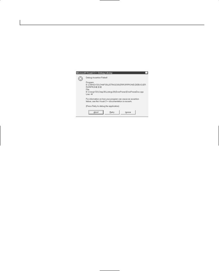


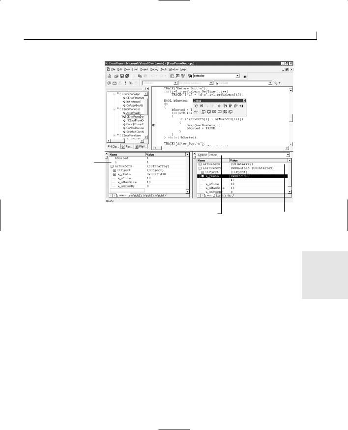
Using the Debugger and Profiler |
693 |
FIGURE E.11.
The Watch window displays contents of variables while debugging.
The Watch window
The Context combo box |
The Variables window |
The Variables window always shows the local variables of the function displayed in the Context combo box at the top of the window. To get to your current function, you can drop this combo box list to display all the functions that were called in turn. This is the call stack and shows your current context within the program by showing the list of func-
tions that have been called in order to get to the program’s currently executing function E where the debugger has stopped. When you select a different function, the relevant local
variables are shown for that function level.
You can expand any object pointers shown by clicking the plus symbol next to the pointer name. The special C++ this pointer is always shown for class member functions and can be opened to show all the member variables for the current object.
The Watch window lets you enter variable names from the keyboard or drag variable names from the editor window (after selecting and inverting them with the mouse point). The values that are held in the displayed variables are shown until they go out of scope (that is, aren’t relevant to the function currently being debugged).
You can also enter simple casts and array indexes in the Watch window to show related values. Right-clicking the mouse can switch the displayed values between hexadecimal

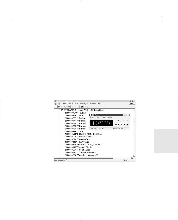
Using the Debugger and Profiler |
695 |
These tools generally let you track operating-specific items such as Windows messaging, running processes, and registered OLE objects to enhance your available information while debugging your application.
Using Spy++
Spy++ is undoubtedly one of the most useful of these tools. With Spy++, you can see the hierarchical relationships of parent to child windows, the position and flags settings for windows, and base window classes. You can also watch messages as they are sent to a window.
When you first run Spy++, it shows all the windows on the current desktop, their siblings, and the base Windows class of each object (see Figure E.12). The view shown in Figure E.12 has been scrolled to shown the standard Microsoft Windows CD Player. Spy++ shows you all the buttons and combo boxes, which are windows in their own right as child windows of the main CD Player window.
FIGURE E.12.
The Spy++ initial view of the Windows desktop showing the CD Player portion.
E
If you click the Spy menu, you are shown the following options:
●Messages. You might find that the Messages view is probably one of the most useful options because you can use it to watch messages that are sent to any window (including your own application). You can also filter these messages so that you don’t receive an avalanche of Mouse Movement messages.
To use messages, select this option to display the Message Options dialog box shown in Figure E.13. You can then drag the finder tool over any window in the
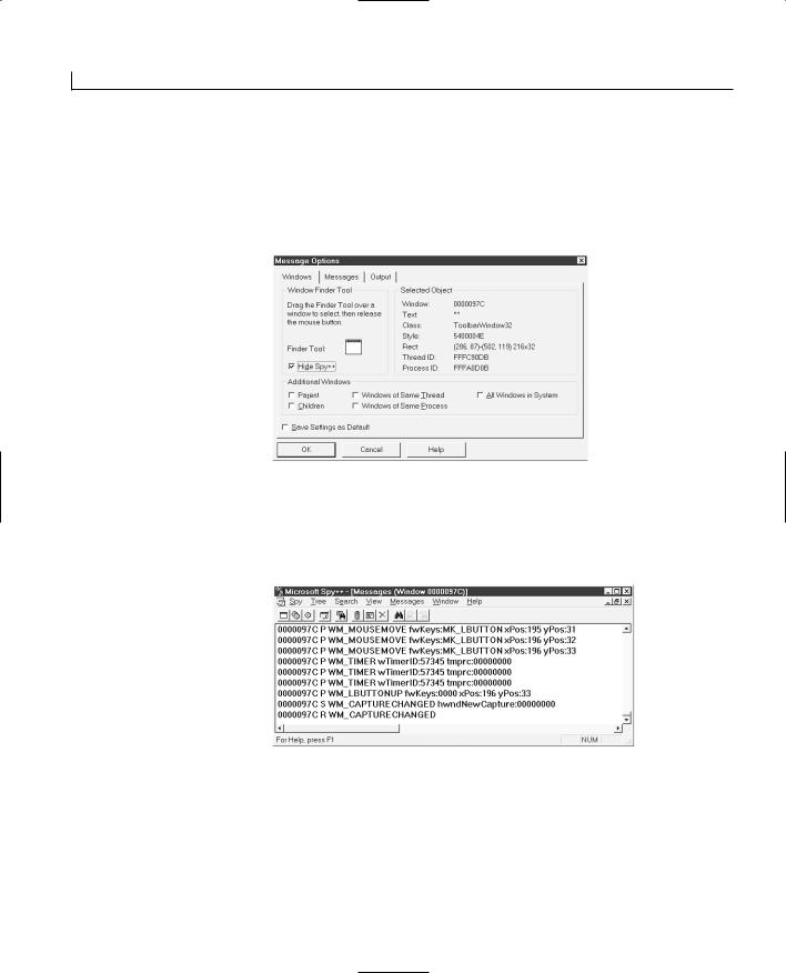
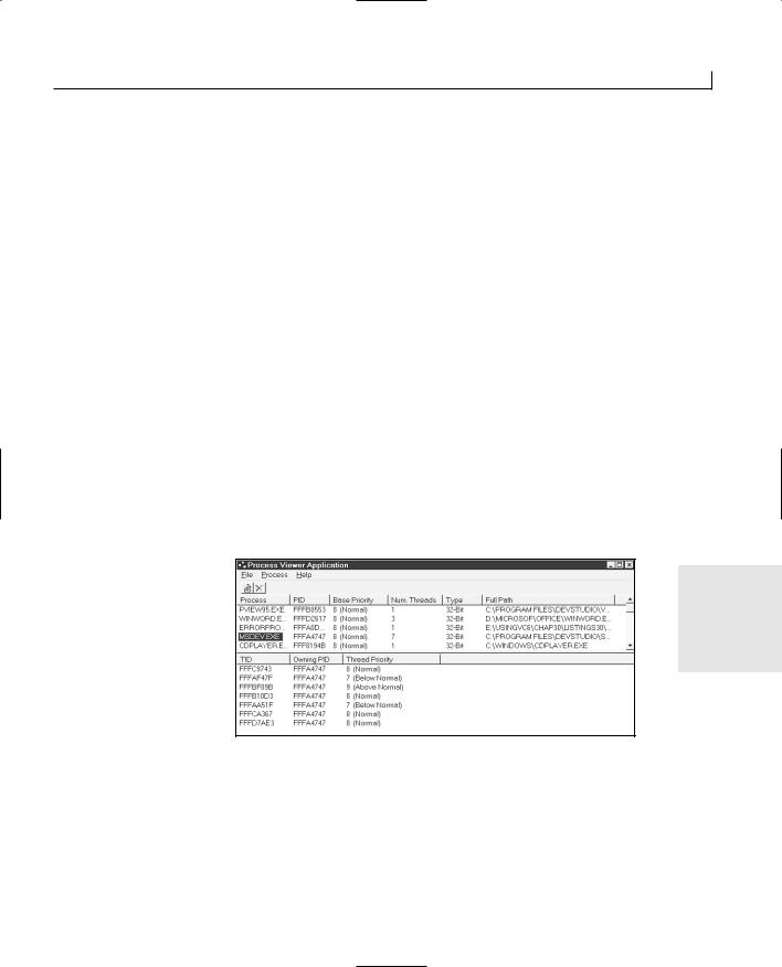
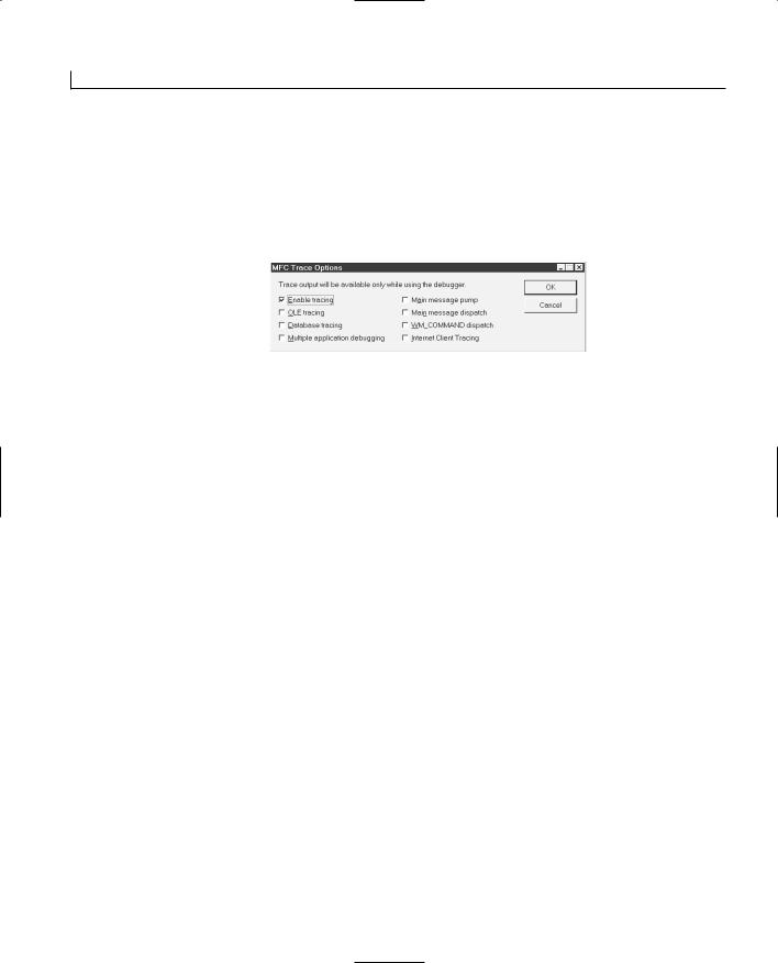

APPENDIX F
Using MFC’s Helper
Classes
by Jon Bates
Using the Collection Classes
You’ll quickly find that in any object-oriented program you write, objects must be grouped and stored into collections of different types and sizes. Once again, the MFC comes to the rescue with sets of easy-to-use classes and templates to help with this common requirement.
The collection classes fall into three broad categories—arrays, maps, and lists—that have their particular niches.
Arrays are the mainstay of collection classes and are useful for implementing object containers. Each object in an array has a zero-based position or index, which is used to locate and reference the object.
Lists are useful when you want to think of your data as being linked sequentially, each item to the next. They are useful when you must

Using MFC’s Helper Classes |
701 |
One of the most useful aspects of these array classes is their capability to grow dynamically. Normal C/C++ arrays are predefined in size and can be extended only by lots of messy reallocations of memory. The collection classes hide these reallocations so that you can simply call the Add() member of an array object to add a new value. For example, to add strings to a CStringArray, you can use code similar to this:
CStringArray myStringArray; myStringArray.Add(“Red”); myStringArray.Add(“Green”); myStringArray.Add(“Blue”);
You can then find the size of an array by calling the GetSize() function; for example, the following line used after the previous lines would return three items into nNumberOfItems:
int nNumberOfItems = myStringArray.GetSize();
You can also set the array to a specific size using the corresponding SetSize() function, which will extend or truncate the array to the specified size you pass.
Values can be set to the array by using the SetAt() function that passes a zero-based index and the value to be stored. SetAt() will assert whether the index is larger than the current array size. You can then retrieve values from the array using the GetAt() function, which will return the value at the index position that you specify. You might use these functions with a CWordArray like this:
CWordArray myWordArray; myWordArray.SetSize(20); myWordArray.SetAt(0,200); myWordArray.SetAt(19,500);
TRACE(“Value at index position 19 is %d\n”, myWordArray.GetAt(19));
These lines will set the first element of a 20-element array to 200 and the last to 500 and |
|
|
display the value 500 when executed. You can still grow the array by calling the Add() |
|
|
|
||
function and find the uppermost valid index by calling GetUpperBound(), which will |
F |
|
return the zero-based index, or –1 if there are no elements present. |
||
|
||
You can use the [] operators to set and get values at a specific index just like a normal |
|
|
C++ array. For example, the GetAt() and SetAt() functions in the previous lines could be |
|
|
replaced with the [] operators like this: |
|
|
|
||
myWordArray[0] = 200; |
|
|
myWordArray[19] = 500; |
|
|
TRACE(“Value at index position 19 is %d\n”, |
|
|
myWordArray.GetAt[19]); |
|


Using MFC’s Helper Classes |
707 |
Creating Custom Collection Classes
You might want to customize the collection classes to use your own objects rather than the generic CObject-derived classes. Customization offers several benefits because you can make an array, list, or map that will accept and return only your specific type of object. If you accidentally try to add the wrong sort of object to a customized array, list, or map, the compiler will issue an error message to notify you. The other advantage is that you don’t have to cast generic CObject* pointers (that is, from a CObArray) back to your specific object to use it.
This sort of customization is known as type-safety; in large programs it can be invaluable for stopping accidental assignments of the wrong class. A set of templates, CArray, Clist, and CMap, lets you easily create an array, list, or map to store, use, and return objects of your specified type only. Templates are a complex subject, but you don’t
have to worry about writing templates; the MFC-provided templates defined in the afxtempl.h header file will do for these type-safe collection classes. For the scope of this section, it is best to think of templates as large macros that generate lots of code based on your parameters when compiled.
The templates will give you access to all the normal functions in the array, list, or map classes discussed in the previous sections. However, instead of using generic CObject- based parameters and returned values, you can define your own types as parameters and return values.
To use the templates in your program, you’ll need to include the following header line in each module (.cpp/.h file) that uses the template definitions:
#include “afxtempl.h”
You can then define your own custom type-safe class using the template syntax like this for an array of custom objects:
CArray<CMyCustomClass*, CMyCustomClass *> myCustomClassArray;
The < and > symbols used in the definition should be thought of as angle brackets (not F greater-than or less-than conditional operators). The previous line uses the CArray tem-
plate to create an instance of myCustomClassArray. The first CMyCustomClass* parameter specifies types of object pointers you want the array to return when you use GetAt() and other access functions. The second CMyCustomClass* specifies the type that should be used for the input parameter definitions. Then all the functions that store objects, such as SetAt() and Add(), will accept only pointers to objects of your specific CMyCustomClass.
For example, you can create an array that takes and returns only pointers to the specific


Using MFC’s Helper Classes |
709 |
The CStatic object would be happily stored along with the CPlanetDets objects, causing untold havoc when you try to retrieve the CStatic object, thinking it’s a CPlanetDets object.
The template used to generate type-safe lists is CList; it takes the same general form as
CArray:
CList<CMyCustomClass*, CMyCustomClass *> myCustomClassList;
Again, the first parameter is the required returned object type, and the second parameter specifies the accepted object types for functions that accept elements for storage.
All the functions available for lists are available for your own specific type-safe customized lists, again checking and returning your specified types. Therefore, the equivalent list-based code for the planet storing array would be coded like this:
CList<CPlanetDets*,CPlanetDets*> myPlanetList; myPlanetList.AddTail(new CPlanetDets
(4878, 0.054, 57.91, 87.969)); myPlanetList.AddTail(new CPlanetDets
(12100, 0.815, 108.21, 224.701)); myPlanetList.AddTail(new CPlanetDets
(12756, 1.000, 149.60, 365.256)); POSITION pos = myPlanetList.GetHeadPosition();
while(pos) TRACE(“Diameter = %f\n”,myPlanetList.GetNext(pos)->m_dDiameter);
The template for customized maps differs from the list and arrays in that it needs four |
|
|
parameters: an input and a return value for both the key and element value. So the |
|
|
general form is like this: |
|
|
CMap<MyType, MyArgType, CMyCustomClass *, CMyCustomClassArg *> |
|
|
myCustomClassMap; |
|
|
The first parameter, MyType, specifies the internally stored key value for each map asso- |
|
|
ciation. This can be any of the basic types such as int, W O R D, D W O R D, double, float, or |
|
|
F |
||
CString, or it can be a pointer to your own specific type. |
||
|
||
The second parameter, MyArgType, specifies the argument type used to pass key values in |
|
|
and out of the map functions. |
|
|
The third parameter, CMyCustomClass *, is how you want the internal element values to |
|
|
be stored (as specific type-safe pointers to your objects). |
|
|
The fourth parameter, CMyCustomClassArg *, specifies the argument type used to pass |
|
|
your element values in and out of the map functions. For example, to associate the planet |
|
|
details with their names, you might code the following: |
|


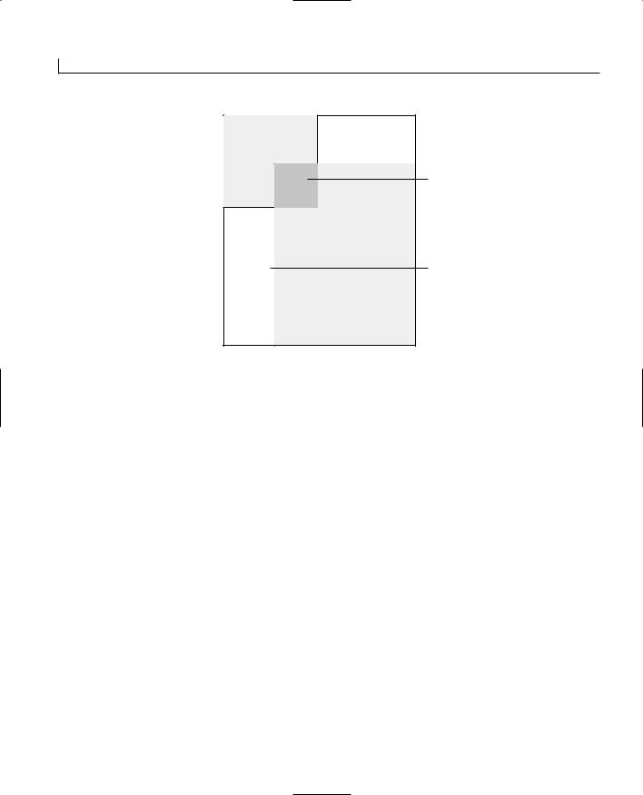
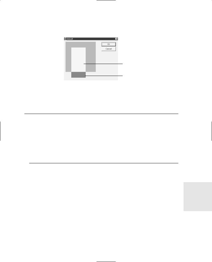

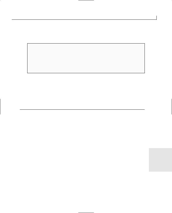

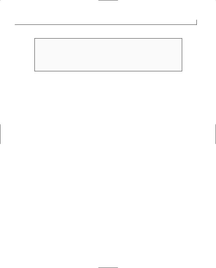
Using MFC’s Helper Classes |
719 |
USING CTime WITH DATABASES
You might find it convenient to use CTime when using ODBC-based databases because the RFX recordset transfer macros know only how to handle CTime objects directly and don’t know how to handle COleDateTime objects without conversion. If you use DAO databases, COleDateTime can be used directly.
cal in the CTime versions.
Using the COleDateTime Class
COleDateTime is connected with OLE in that it can be used in conjunction with the VARI- A N T structure, often used in OLE automation. Because of the wide range of date and time storage systems, especially in OLE environments, COleDateTime must be capable of converting between all these various types. This support is reflected in its many constructor forms, as shown in Table F.10.
TABLE F.10. CONSTRUCTOR TYPES USED WITH COleDateTime. |
|
|
||
|
Constructor Definition |
Description |
|
|
|
|
|
|
|
|
COleDateTime() |
Creates an uninitialized COleDateTime object |
|
|
|
COleDateTime(const COleDateTime& |
Copies the values from another |
|
|
|
datesrc) |
COleDateTime object |
|
|
|
COleDateTime(int nYear, int nMonth, |
Initializes the date and time from the |
|
|
|
int nDay, int nHour, |
values passed |
|
|
|
int nMinute, int nSecond) |
|
|
|
|
COleDateTime(const VARIANT& varSrc) |
Converts a date time from a VARIANT structure |
|
|
|
COleDateTime(DATE dtSrc) |
Copies a date time from a DATE structure |
|
|
|
COleDateTime(time_t timeSrc) |
Copies a date time from a UNIX-style time_t struc- |
|
|
|
||||
|
|
ture |
F |
|
|
COleDateTime(WORD wDosDate) |
Copies a date time from the MS-DOS–style values |
||
|
|
|||
|
|
W O R D and wDosTime |
|
|
|
COleDateTime(const SYSTEMTIME& |
Copies a date time from a SYSTEMTIME structure |
|
|
|
systimeSrc) |
|
|
|
|
COleDateTime(const FILETIME& |
Copies a date time from a FILETIME structure |
|
|

Using MFC’s Helper Classes |
721 |
% A |
Saturday |
Day of the week |
% b |
Apr |
Abbreviated month |
Code |
Example |
Description |
|
|
|
% B |
April |
Month |
% c |
04/04/98 18:05:01 |
Date and time in the current locale format |
% d |
04 |
Day of the month (01–31) |
% H |
18 |
Hour (00–23) 24 hour |
%I |
06 |
Hour (01–12) 12 hour |
%j |
094 |
Day of the year |
% m |
04 |
Month (01–12) |
% M |
05 |
Minute (01–59) |
% p |
PM |
AM/PM indicator for locale |
% S |
01 |
Second (01–59) |
% U |
13 |
Week of year (00–51) with Sunday as first day of week |
% w |
6 |
Weekday (0–6) 0=Sunday |
% W |
13 |
Week of year (00–51) with Monday as first day of week |
% x |
04/04/98 |
Date in the current locale format |
% X |
18:05:01 |
Time in the current locale format |
% y |
98 |
Two-digit year (00–99) |
% Y |
1998 |
Four-digit year (0100–9999) |
% z or % Z |
GMT Daylight Time |
Time zone name/abbreviation |
% % |
% |
A percent sign |
% # c |
Saturday, April |
Current locale long date and |
|
04, 1998 18:05:01 |
time |
% # x |
Saturday, April |
Current locale long date |
|
04, 1998 |
|
F
You can use the following lines to generate a message box displaying your machine’s date and time like this:
COleDateTime dtCurrent;
dtCurrent = COleDateTime::GetCurrentTime(); AfxMessageBox(dtCurrent.Format(“Today is %a %b %d, %Y”));


Using MFC’s Helper Classes |
725 |
You can easily construct CString objects as an empty string or initialized by passing one of many differing types of text representation systems to the constructor. The various forms of CString construction are shown in Table F.15.
TABLE F.15. CONSTRUCTOR TYPES USED WITH CString.
Constructor Definition |
Description |
CString() |
Creates an empty zero-length string |
CString(const CString& strSrc) |
Copies the contents from another CString |
CString(LPCSTR lpsz) |
Copies the contents from a null-terminated string |
CString(const unsigned char* psz) |
Copies the contents from a null-terminated string |
CString(LPCTSTR lpch, int nLength) |
Copies nLength characters from a character array |
CString(TCHAR ch, int nRepeat = 1) |
Fills the string with nRepeat copies of character ch |
CString(LPCWSTR lpsz) |
Copies a Unicode null-terminated string |
|
|
When you’ve constructed a CString object, there are many ways in which you can add or assign text to it. The operator overloads provide simple assignments via the = operator, or concatenation of two strings by the + or += operators, as shown in the following lines:
CString strTest; strTest = “Mr Gorsky”;
strTest = “Good luck “ + strTest; AfxMessageBox(strTest);
When this code is run, the string is initially set to “Mr Gorsky”; then “Good luck “ is prefixed by the + operator.
You can find the length of a string by calling the GetLength() member function, which returns an integer representing the number of characters the string currently holds. You can also test whether a string is empty by calling IsEmpty(), which returns TRUE if it holds no characters.
You can also drop the contents of a CString object by calling Empty(), which will then F force the string to be zero length.
Many functions require old C-style strings rather than a CString object; you can use the (const char *) or LPCTSTR casts to give functions access to the CString object’s internal buffer as if it were a C-style null-terminated string (but only for read access). Visual C++ will implicitly cast the CString to a null-terminated string if a specific function has a pro-

Using MFC’s Helper Classes |
727 |
if (strName.Compare(“Piper”)<0) AfxMessageBox(“TRUE”);
This comparison also takes notice of the case of the compared strings. You can use the CompareNoCase() equivalent to ignore differences in case.
String Manipulation
The BASIC language had three very useful manipulation functions— Mid$, Left$, and Right$—which are now available as the CString Mid(), Left(), and Right() functions. Their job is to copy out sections of a specified string. You can pass the Mid() function a start position and optionally a number of characters to copy (it defaults to all characters if not specified), and Mid() will return another CString containing the specified section. You can extract a number of characters from the left of a string by passing the required count to the Left() function. Right() returns the corresponding specified number of characters from the right of the string as shown in these lines:
CString strText(“I saw three ships a sailing”);
TRACE(“%s\n”,strText.Left(5));
TRACE(“%s\n”,strText.Mid(6,11));
TRACE(“%s\n”,strText.Right(7));
When run, these lines will display the following trace output:
I saw three ships sailing
Notice that the word a used between ships and sailing isn’t displayed in the trace output because that portion of the string is never extracted.
You can use the MakeUpper() and MakeLower() functions to change all the characters in a string to upperor lowercase and MakeReverse() to reverse the string.
Spaces, newline characters, and tabs can be trimmed from the left of a string with the TrimLeft() function and from the right with the TrimRight() function.
Searching Strings |
F |
|
|
You can look for specific substrings or characters from a string by using the Find(), |
|
ReverseFind(), or FindOneOf() functions. |
|
You can pass a single character or string to the Find() member function to look for an |
|
instance of that character or string in the context string. If the character or substring is |
|
found, its zero-based position will be returned; otherwise –1 is returned to indicate that |
|
the substring or character isn’t present. The following lines search for the word “you” and |
|

Using MFC’s Helper Classes |
729 |
% % |
none |
Display a percent sign %. |
The following example combines some of these common types to display a message box containing the text “There are 1.609340 Kilometers to 1 Mile”:
CString strFormatMe; char *szKm = “Kilometer”;
double dKmsPerMile = 1.60934; strFormatMe.Format(“There are %f %ss to %d %s”,
dKmsPerMile,szKm,1,”Mile”);
AfxMessageBox(strFormatMe);
You can pass extra formatting specification flags to the width and precision of each output field and its alignment. These flags are passed after the % sign, but before the type (refer to Table F.16) in the following format:
%[flags] [width] [.precision]type
The flag value can be any of the following characters:
●- Left-aligns the field (otherwise it is right-aligned).
●+ Displays a + or – to indicate the numeric sign (defaults to just show – for nega-
tive numbers).
● 0 Pads the width with zeroes
The width then specifies the minimum number of characters that should be displayed, and the .precision specifies how many characters should be displayed after a floating point.
STRING FORMATTING
The CString Format() function uses the same format specifier codes as the C-style printf() and sprintf() (print and string print) functions. C programmers might be more familiar with the
formatting codes of these printf() functions, which can also be used and applied to the F
CString Format() function.