

11Multiplexing technologies
The DTS changed the ATS. DTS have a lot of advantages (reliability, the Terminal station costs, production fabricability, small dimension and weight), but the important disadvantage is the short regeneration section length. the line path cost rise comparing with the ATS.
PDH DTS have next important disadvantages:
System justification difficulty when asynchronous digital bitstream (DBS) multiplexing, the higher transmission rate the higher difficulty.
“slip” type mistakes presence that lead to the frame alignment signal failure that causes the commutation channel break.
difficulty and bulkiness of DBS extracting from the higher hierarchy level group DBS.
Control system absence.
T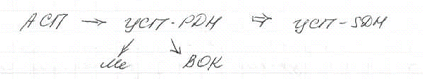 hese
disadvantages were solved in new SDH DTS.
hese
disadvantages were solved in new SDH DTS.
SDH DTS is the FOTS version as the 1st SDH DTS was operating over the fiber.
11.1 SDH DTS
The 1st SDH DTS was developed in America in 1986 and was named as SONET (Synchronous Optical Network).
Within the ITU the united SDH hierarchy was accepted.
The DTS hierarchy:
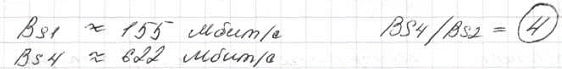
The bitsteam ransmission rate, Mb/s hierarchy branches recommendations
There was 1, 2… level numeration in American hierarchy. The 1, 4, 16 … levels appear in the legalized by the ITU SDH hier archy, they show in how many times the primary level DBS (PDB) transmission rate is smaller that this level DBS rate. The multiplication factor for the nearest levels is equal to 4.
The 1st digital radio relay TS used lower SONNET equipment levels ITU introduced one more level with number 0, the transmission rate in which is in 3 times smaller than the 1st level rate (52 Mb/s), it is specialized for the RRTS trunk organization.
What is the difference between the PDH DTS hierarchy branches:
The different levels of these hierarchies have the different transmission rate and the different hierarchy branches digital bitstreams (DBS) but the same hierarchy level differ in transmission rate as they are structured in a different way.
 The primary digital channel (PDC)

TS = 8 bits = 1 byte
There are 8 bit instead of 12 digits in the A type. Here is nonlinear coder μ type – 7 bits.
B=fcl; fcl = ffr * Nfr
Nfr – the bit quantity in the transmission frame.
FA – Frame alignment
VBC
8 digits – CIS
The PDH and SDH difference:
The PDC number in DBS of this hierarchy level is in integer times bigger than the PDC of the previous hierarchy levels.
T he
transmission rates are not multiple as the different service bits
number is used in these levels.
he
transmission rates are not multiple as the different service bits
number is used in these levels.
The DBS transmission rates of corresponding hierarchy levels are multiple in SDH.
The only exception is the zero level, which has the 3 times smaller transmission rate than the first.
The zero level DBS is widely used in the digital RRTS.
The DBS multiplexing is performed in a synchronous mode (0, 1st, 4th and so on SDH hierarchies) the name SDH.
The SDH equipment can be matched with the earlier developed PDH equipment.
The PDH DTS plesiochronous multiplexing mechanisms are provided in order to perform the different PDH DBS transmission over the SDH equipment.
Thereby there are 2 multiplexing methods in SDH equipment:
Synchronous multiplexing for the SDH DBS
Plesiochronous multiplexing for the PDH DBS that are inputted into the group aggregate signal.

TS (DTS) SDH PDB TS aggregate signal
Channels TDB electrical/optical – network interface SDH TS are
and others. named
Initial signal (tributaries) synchronous
Multiplexers
The group aggregate signal forming from the initial signal (tributaries) multiplexer is performed with the help of corresponding informational structures in the synchronous SDH.
C – container
VC – virtual container
TU – tributary unit (subunit)
TUG – tributary unit group
AU – administrative unit
AUG – administrative unit group
STM – synchronous transport module
STM-N – STM of the N-th order (0, 1, 4, 16 and so on)
The hierarchy levels:

t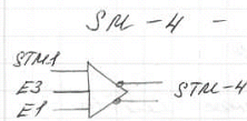 he
4th
level synchronous multiplexer
he
4th
level synchronous multiplexer
The different layers are used in SDH equipment for the SDH network modeling and control processes simplification.
The layerwise network designing (equipment)
Isn’t a new invention, it was used also in ATS, DTS PDH.
There are next layers types:
Channel layer
Network trunk layer
Transmission environment layer
Channel layer is equivalent to the ATS individual equipment. The DBSs come to it from the subscribers terminals (ST). These bitstreams are the PDH equipment DBS (E1, E3, E4 and others).
There are access points in the channel layer (AP) at which the DBSs come from the STs.
Network trunk layer includes 2 layers: the highest and the lowest levels, which also have their own APs.
This (2nd) layer is analogous to the secondary and master groups layers in ATS.
Transmission environment layer consists of 3 layers:
Multiplexing section layer, MS
Regeneration section layer, RS
Physical circuit layer
This layer is analogous to the ATS Conditioning Facilities and Line Path.
Each informational structure consists of the Overhead (OH) and the Payload (PL).
These informational structures are formed in the corresponding layers.
Functional layers Informational structure
Channel layer (type) T (T1, T2 and so on)
Network trunks layer
The lowest order C, VC
The highest order TU, TUG
Transmission environment layer: AU, AUG, STM-N
Section layer:
MS
RS
Physical environment layer