

3. Digital linear path
3.1 The line path (lp) structure and characteristic
See the Complex assignment directions.
The structure chart of the LP is analogous to the Analog TS with the exception of regenerator using as an intermediate station. If the regenerator is situated in the non-serviced repeater station it’s named as the non-serviced regenerating station.

3.2 Lp Coder (lpc)
LPC forms convenient for the transmission through the line pulse signal. LPC is installed in all blocks of the terminal station structure chart that introduce the LPTE (line path terminal equipment).
In DTS with the direct coding LPC is installed in transmission path at the output of ADE and the reverse equipment (decoder) – in the receiving path.
In this case the coder simplifies the signals transmission not only though the general cable, but also through the intrastation junction cables as well – the corresponding interface coder (primary, secondary…).
The DTS terminal equipment is arranged by racks.
The ADE equipment is situated on the ADER (ADE Rack) rack.
П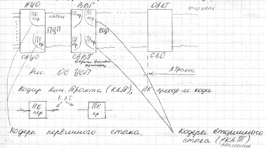 К
– code transformer
К
– code transformer
КЛТ – LPC
ПЦП – PDB (primary flow)
ВЦП - SDB
ВВГ – Secondary Time Multiplexing (STM)
ОАЛТ – LPTE
Physical line
Primary (secondary) interface
СЛО – line equipment rack
DTS TS (DTS terminal station) with the direct coding:

Let’s observe the digital signal transmission through the line path specifies and its requirements to the LPC.
№ |
Specifies |
Requirements |
1 |
The matching devices, through which the station equipment is connected to the cable, as a rule, use the transformers that don’t transmit the direct current |
It is desirable that signal formed in LPC doesn’t include the constant component and the nearest to it frequencies |
2 |
The
physical lines (cable) distort the transmitted signal as more as
its spectrum wider due to the amplitude-frequency characteristic
rise with the rise of frequency.
|
So it is desirable that the formed signal has as narrow bandwidth as possible. |
3 |
Interference inducted in the digital line path causes the errors in regeneration process of this signal |
It is desirable that the formed by LPC linear signal has the redundancy that allows at least to control the transmission quality (in the modern OFTS to correct errors as well) |
4 |
It will be shown that the correct operating of majority of regenerator schemes demands the long “free”(zero) intervals absence in the linear signal |
It is desirable to use the coders that don’t allow the big quantity of 0 in sequence. |
The LPC can vary in:
By the amplitude gradation number of transmitted pulse signal:
Binary codes B
Ternary codes T (quasi ternary)
Multilevel codes (e.g. quaternary code Q)
By the linear signal pulse grouping:
Block codes
Non-block codes
By the constant component presence in the linear code
Balance codes (constant component is absent)
Non-balance codes (constant component is present)
Let’s observe next linear codec that is used in DTS PDH operating over the metal cable. Such systems are:
AMI code (Alternate Mark Inversion coding)
Binary unipolar code BU (PCM-12, PCM-15)
HDB code (High Density Bipolar) (decreases the 0s number in sequence) – HDB-3: the 0s number can’t be more than 3 in sequence.
AMI type LPC
The operating mode:
T he
rule: changing of the pulse polarity.
he
rule: changing of the pulse polarity.
Let’s observe one of such coder variants
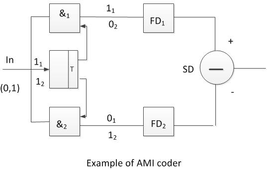
Coincidence circuit “and”.
If there is 0 at the input than 0s are at the &1 and &2 outputs. In the initial state there is 0 at the second input of &1. When there is first 1trigger is tipped over and the 1 goes to the second input of &1, at the second input of &2 – 0.
At the output of &1 is 1, at the output of &2 – 0.
The 1 starts the forming device FD1 (e.g. trigger), which forms the pulse with the required amplitude and duration. This pulse is sent to the subtracting device. The first pulse goes through without changing.
The second unity opens &2 and closes &1. The pulse after FD2 is sent to the negative input of SD, so it appears with sign “-”.
The code transformer scheme can form the signal in 2nd case as the trigger with complementing input can be in any position.
Let’s observe 2nd variant of AMI code transformer construction
Two nodes – trigger with complementing input (T), DSS – delayed signal subtracting. T – the clock interval delay devise

Let’s observe the time diagrams in different points of this scheme.
DE – delay element

This (second) variant of scheme is used in PCM-15 equipment in order to form binary unipolar code in a following way:
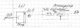
Recoded binary signal transformed into the quasi ternary by using of delayed signal subtracting scheme (DSS) in the intermediate and terminal stations regenerators at input of the deciding making device (threshold matching circuit), that makes a decision on what symbol was transmitted.
LPC Code Transformer (CT) with AMI forms the bipolar signal in which the constant component is absent; the first condition is performed by this.
C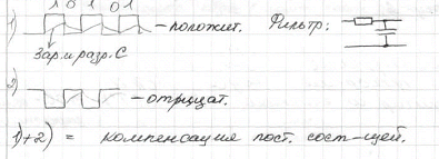 harging
and discharging of capacitor
harging
and discharging of capacitor
Constant component compensation.
The digital signal (bitstream) description and showing can be performed in two following ways:
In a view of symbols sequence
0 -1 +1 -1 0 0 – the sequence of ternary symbols
0 1 1 1 0 0 – the sequence of binary symbols
In a view of pulse sequence
S ymbols
unipolar pulses NRZ Tp = Tcl
Pulses bipolar pulses
RZ signal Tp = 0,5 Tcl
RZ – returning to zero during the clock interval
 ,
as a rule Tp = 0,5 Tcl (RZ)
,
as a rule Tp = 0,5 Tcl (RZ)
Tp = Tcl (NRZ)
Let’s observe pulse signals spectral characteristics of different codes.
Pulse signal represents the sequence with a determinate clock interval (Tcl = const) and a random amplitude. It’s known that the random process is described by an energy spectrum G(f).
Note:
The periodical signals spectrums are ruled. The nonperiodical signals spectrums are soiled.
The random signals energy spectrum can contain both ruled and soiled components.
G(f) = Gd(f) + Gc(f), where
Gd(f) – discrete component (ruled),
Gc(f) – continuous component (soiled).
These discrete components have the same shape, but different by value envelops, which are proportional to the square of single pulse spectrum.
The energy spectrum diagrams
-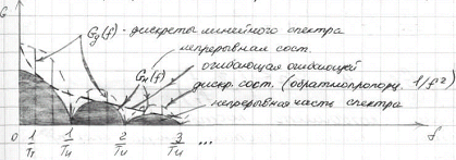 the
linear spectrum discrete
the
linear spectrum discrete
-the continuous component
-the envelop of the envelop
-the discrete component (inversely as the square of f)
-the continuous part of the spectrum
The separated discrete components of the discrete
spectrum follow with
 period.
Let’s observe spectral diagrams for 3 signal types:
NRZ type binary unipolar signal
RZ type binary unipolar signal
RZ type AMI signal (ternary bipolar signal that has the Tp = 0,5 Tcl pulse duration as a rule)
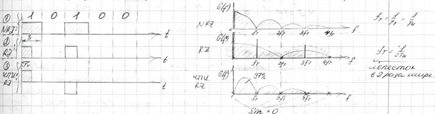
Leaf is in 2 times wider
The spectrum continuous component for the RZ unipolar code is two times wider than for the NRZ code. The RZ code discrete component contains the zero and all even harmonics. All discrete components, a zero component excepted, are absent in NRZ cod
It is convenient to use the 2nd variant of this linear path coder scheme in order to determine the energy spectrum of AMI code.
AMI LPC

Out
GAMI(f)
G in(f) linear four-pole
In
It is easy to show, that for the pulse signal that has equal 1 and 0 occurrence probability:
![]()
The transmission function module
в зс
– DSS
зс
– DSS
This formula gives a possibility to draw an energy spectrum diagram if the input signal energy spectrum is known.
As follows from the diagram AMI signal energy spectrum consists of the same width leaves that are equal to fcl. The biggest is the 1st leaf.
It can be shown that there is more than 97% of the whole signal energy. That’s why the linear signal spectrum width is considered as approximately equal to fcl in DTS.
![]() than
the digital signal spectrum width
than
the digital signal spectrum width
![]() .
.
Comparing of the 1st, 2nd and 3rd energy spectrums shows that there are absent discrete components and 0th component as well in AMI signal spectrum, that is the constant component is absent. Additionally it is seen that the signals energy at low frequency band near the 0 frequency is small, while there is maximum energy in unipolar signal at the same frequencies.
That why the signal recoding with a help of AMI method decreases the distortions caused by the line path.
Unipolar signal
A MI
MI
f At least the 1st leaf of energy spectrum is placed in this bandwidth.
It is obvious that the AMI signal will be received with the smaller distortions than the unipolar signal, as the signals spectral components in the low frequencies band, where the Line Transformer inputs the biggest distortions number, practically are absent.
Binary Unipolar (BU) Line Path Coder (LPC-BU)
This type of coder is used in PCM-12 and PCM-15.
The differences of this linear coding method comparing to the AMI can be understood after these systems line paths comparison.
AMI LPC fragment

Binary; DSS; AMI; ternary; communication line cable; signal/noise; correcting amplifier; D
BU LPC fragment

As follows from the given schemes the line path with the BU code differs from the line path with the AMI code in the DSS scheme (delayed signal subtracting) location.

DSS – is the linear four-pole with the
transmission function
![]() DSS.
DSS.
The regeneration section cable is the linear four-pole also, as well as the correcting amplifiers.
The signal at the output of Correcting Amplifier (at the input of TCC – the threshold comparison circuit) is the same for both cases, although the different signals are sent.
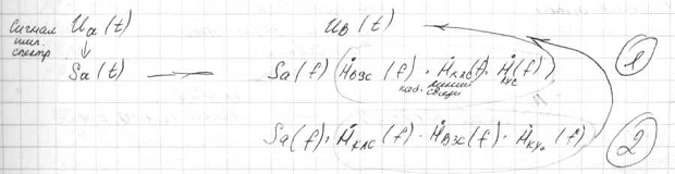
The product doesn’t depend on the multipliers position changing.
The noises and the signal come together at the input of the regenerator; the points of solving are different for these schemes; that is the line path immunity for these systems are different due to DSS frequency characteristic (attenuation dependence on frequency).
Amplitude frequency characteristic of the DSS scheme is:
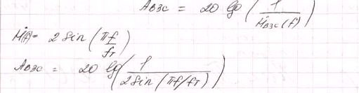
The frequency characteristic view:
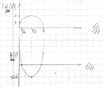
It is obvious that the DSS scheme suppresses the low frequency noise, so it is efficient to use it when the level of these noises is high.
Nowadays the AMI and the HDB-3 codes are used for the wired DTS.
Let’s consider the HDB-3 code.
The operating mode of this coder:
If n0 < 4 then the bipolar signal forming is performed according to the AMI algorithm.
If n0 = 4 the bipolarity violation is performed by the insert forming.

n0 – the number of 0s in the sequence in the input signal.
n1 – the number of 1s between the given bipolarity violation BV–k and the previous bipolarity violation BV–k-1.
W – is the pulse that has the opposite polarity to the previous pulse.
V – is the pulse that has the same polarity to the previous pulse.
Let’s consider the example of such coding type:

Binary symbols of signal
NRZ signal
HDB-3
BV-1 BV-2
insert 1 insert2
The 1st insert can be any, for example 000V.
The 2nd insert corresponds to the number of 1s between the BV–k and the BV–k-1.
The pulses of the 1st and 2nd inserts are characterized by the polarity. The 2nd insert has the positive polarity, the 1st – negative.
The use of inserts with the big (more than 3) 0 number sequences prohibition improves the important regenerator unit operation – Clock frequency former (Clock Driver – CD). The insert is performed by the BV in order to obtain the insert position determination and its extracting from the signal possibility.
The BV can lead to the constant component recover. The insert alternation is used in this coder algorithm in order to avoid this situation.
The simplified structure chart of the HDB-3 LPC
P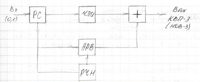 C
– SR – the shift register – the 4 clock intervals sequence
memory device;
C
– SR – the shift register – the 4 clock intervals sequence
memory device;
РЧH – FZR – the four 0s sequence register device.
АРВ – IPA – the insert polarity analyzer and the necessary insert forming device.
ЧПИ – AMI – the coder, which uses the AMI algorithm.
It’s not possible to use the bipolar signal in the DTS that work over the optical fiber cable (OFC) as the amplitude modulation is used in the modern FOTS (fiber optical transmission systems) – the light modulation by its intensity, so unipolar binary signals are used as the linear FOTS codes and the several interface codes (inside the equipment). The code redundancy is used in order to obtain the required signals features.
The corresponding block codes have the next view BmBn.
B – binary block at the input,
m –digits.
The output signal block Bn.
B – binary block,
n –digits, n > m.
The example:
5B6B
The five digits binary code is transformed into the six digits one.
The additional bits in the output block give the possibility:
The constant component value stabilization for its easy adjusting in the receiver.
The redundancy presence gives a possibility to control the binary signal transmission quality.
The pulse signal transmission quality control is performed by the code algorithm violation: in the AMI signal – by the pulse polarity alternating violation; in the HDB-3 - by the insert polarity alternating violation.
The multilevel code is used for the subscriber line in the modern DTS.
Last time the block linear codes with multilevel signals are used in modern DTS of this network segment called xDSL, the amplitude grades number is more than 3.
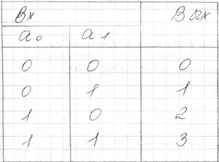
The easiest example of such LPC is 2B1Q code.
2B – the input signal is grouped, that is 2 bits of input signal (0, 1).
1Q – is transformed into one quaternary symbol in this code.

Input binary signal Bi (the transmission rate of binary signal at the LPC input – the informational rate)
The output signal symbols Bs (the symbols transmission rate – the symbols rate)
The output signal
Each bit is correspondingly transformed into the one quaternary symbol by the coding devise. There are a lot of algorithms of such transformation. The easiest of them corresponds to the recalculation rule of the binary numbers into the quaternary.
As a result of that LPC coder of such method is like a PCM decoder.
In the equipment with PCM
![]() .
.
Without PLC
![]() Bi.
Bi.
With PLC using Bs = Bi/2 = 0.5 Bi.
Thereby such coder using gives a possibility to decrease the frequency bandwidth in the line, so the signal’s attenuation is decreased that gives the possibility to increase the regenerator section length.
The subscribers line length is 1,5 km – average, and 3-5 km – the maximum.
The general requirements to the LPC:
Narrow frequency bandwidth (in order to decrease the irregularity of cable attenuation depending on the frequency)
Small energy concentration at low frequencies
The constant component absence
Easy clock frequency wave extracting (for the clock driver (extractor) operation)
The redundancy using in order to control the path without the communication break.