

Part 13. Broadcast Storms
In the last part, you discovered how switches learn where the nodes are located. With all of the switches now connected in a loop, a packet from a node could quite possibly come to a switch from two different segments. For example, imagine that Node B is connected to Switch A, and needs to communicate with Node A on Segment B. Switch A does not know who Node A is, so it floods the packet (Fig. 17).
Fig. 17. Broadcast storm results in severe network congestion
|
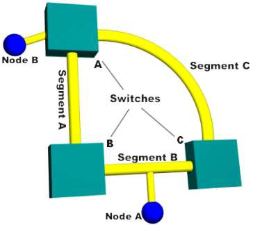
The packet travels via Segment A or Segment C to the other two switches (B and C). Switch B will add Node B to the lookup table it maintains for Segment A, while Switch C will add it to the lookup table for Segment C. If neither switch has learned the address for Node A yet, they will flood Segment B looking for Node A. Each switch will take the packet sent by the other switch and flood it back out again immediately, since they still don't know who Node A is. Switch A will receive the packet from each segment and flood it back out on the other segment. This causes a broadcast storm as the packets are broadcast, received and rebroadcast by each switch, resulting in potentially severe network congestion.
Which brings us to spanning trees...
Part 14. Spanning Trees
To prevent broadcast storms and other unwanted side effects of looping, Digital Equipment Corporation created the spanning-tree protocol (STP), which has been standardized as the 802.1d specification by the Institute of Electrical and Electronic Engineers (IEEE). Essentially, a spanning tree uses the spanning-tree algorithm (STA), which senses that the switch has more than one way to communicate with a node, determines which way is best and blocks out the other path(s). The cool thing is that it keeps track of the other path(s), just in case the primary path is unavailable.
Here's how STP works:
Each switch is assigned a group of IDs, one for the switch itself and one for each port on the switch. The switch's identifier, called the bridge ID (BID), is 8 bytes long and contains a bridge priority (2 bytes) along with one of the switch's MAC addresses (6 bytes). Each port ID is 16 bits long with two parts: a 6-bit priority setting and a 10-bit port number.
A path cost value is given to each port. The cost is typically based on a guideline established as part of 802.1d. According to the original specification, cost is 1,000 Mbps (1 gigabit per second) divided by the bandwidth of the segment connected to the port. Therefore, a 10 Mbps connection would have a cost of (1,000/10) 100.
To compensate for the speed of networks increasing beyond the gigabit range, the standard cost has been slightly modified. The new cost values are:
Bandwidth |
STP Cost Value |
4 Mbps |
250 |
10 Mbps |
100 |
16 Mbps |
62 |
45 Mbps |
39 |
100 Mbps |
19 |
155 Mbps |
14 |
622 Mbps |
6 |
1 Gbps |
4 |
10 Gbps |
2 |
You should also note that the path cost can be an arbitrary value assigned by the network administrator, instead of one of the standard cost values.
Each switch begins a discovery process to choose which network paths it should use for each segment. This information is shared between all the switches by way of special network frames called bridge protocol data units (BPDU). The parts of a BPDU are:
Root BID ─ This is the BID of the current root bridge.
Path cost to root bridge ─ This determines how far away the root bridge is. For example, if the data has to travel over three 100-Mbps segments to reach the root bridge, then the cost is (19 + 19 + 0) 38. The segment attached to the root bridge will normally have a path cost of zero.
Sender BID ─ This is the BID of the switch that sends the BPDU.
Port ID ─ This is the actual port on the switch that the BPDU was sent from.
All of the switches are constantly sending BPDUs to each other, trying to determine the best path between various segments. When a switch receives a BPDU (from another switch) that is better than the one it is broadcasting for the same segment, it will stop broadcasting its BPDU out that segment. Instead, it will store the other switch's BPDU for reference and for broadcasting out to inferior segments, such as those that are farther away from the root bridge.
A root bridge is chosen based on the results of the BPDU process between the switches. Initially, every switch considers itself the root bridge. When a switch first powers up on the network, it sends out a BPDU with its own BID as the root BID. When the other switches receive the BPDU, they compare the BID to the one they already have stored as the root BID. If the new root BID has a lower value, they replace the saved one. But if the saved root BID is lower, a BPDU is sent to the new switch with this BID as the root BID. When the new switch receives the BPDU, it realizes that it is not the root bridge and replaces the root BID in its table with the one it just received. The result is that the switch that has the lowest BID is elected by the other switches as the root bridge.
Based on the location of the root bridge, the other switches determine which of their ports has the lowest path cost to the root bridge. These ports are called root ports, and each switch (other than the current root bridge) must have one.
The switches determine who will have designated ports. A designated port is the connection used to send and receive packets on a specific segment. By having only one designated port per segment, all looping issues are resolved!
Designated ports are selected based on the lowest path cost to the root bridge for a segment. Since the root bridge will have a path cost of "0," any ports on it that are connected to segments will become designated ports. For the other switches, the path cost is compared for a given segment. If one port is determined to have a lower path cost, it becomes the designated port for that segment. If two or more ports have the same path cost, then the switch with the lowest BID is chosen.
Once the designated port for a network segment has been chosen, any other ports that connect to that segment become non-designated ports. They block network traffic from taking that path so it can only access that segment through the designated port.
Each switch has a table of BPDUs that it continually updates. The network is now configured as a single spanning tree, with the root bridge as the trunk and all the other switches as branches. Each switch communicates with the root bridge through the root ports, and with each segment through the designated ports, thereby maintaining a loop-free network. In the event that the root bridge begins to fail or have network problems, STP allows the other switches to immediately reconfigure the network with another switch acting as root bridge. This amazing process gives a company the ability to have a complex network that is fault-tolerant and yet fairly easy to maintain.