

Методика радиографического контроля сварных соединений с использованием беспленочных технологий (на примере рентгеновского аппарата рап-160)
Сварные соединения контролируют для выявления пор, непроваров, шлаковых, вольфрамовых, окисных и других включений, подрезов, прожогов, наплывов.
Выявление дефектов при радиационных методах основано на разном поглощении рентгеновского или гамма-излучения участками металла с дефектами и без них. Сварные соединения просвечивают специальными аппаратами.
Оборудование и материалы.
- металлическая пластина 12 мм со швом стыкового соединения;
- цифровой сканер HD-CR35 NDT для получения изображения;
- программа ВидеоРен для обработки изображений;
- запоминающие пластины.
Методика контроля.
1) Подготовка к контролю
Очистить поверхность контролируемого объекта от неровностей, шлака, брызг металла и других загрязнений, изображение которых на снимке могут помешать расшифровке.
Для определения чувствительности контроля на каждом участке установить эталоны чувствительности на контролируемом участке со стороны, обращенной к источнику излучения.
2) Схема просвечивания
В соответствии с ГОСТ 7512 схему контроля производить согласно
рисунку 1

Рисунок 1 - Схемы контроля
1 - источник излучения; 2 - контролируемый участок; 3 - кассета с пленкой
3) Выбор параметров контроля
3.1) На расстоянии 1 метр от контролируемого объекта расположить источник излучения.
Установить защитную кассету с запоминающей пластиной за исследуемым объектом контроля. Рабочая сторона запоминающей пластины (белого цвета) должна быть обращена к рентгеновской трубке.
3.2) На пульте управления от рентгеновского аппарата установить следующие параметры просвечивания: напряжение U=120 кВ, ток I=4,5 мА, время экспозиции t=30 с.
4) Произвести экспонирование пластины.
5) Произвести считывание данных изображения
5.1) Включить сканер.
5.2) После загорания светодиодных индикаторов состояния зеленым светом, поместить запоминающую пластину во входную щель сканера.
5.3) Изображение автоматически передается на ПК. Ход процедуры считывания отображается в окне предварительного просмотра.
6) Сделать выводы по полученному изображению.
Приложение Б
(рекомендуемое)
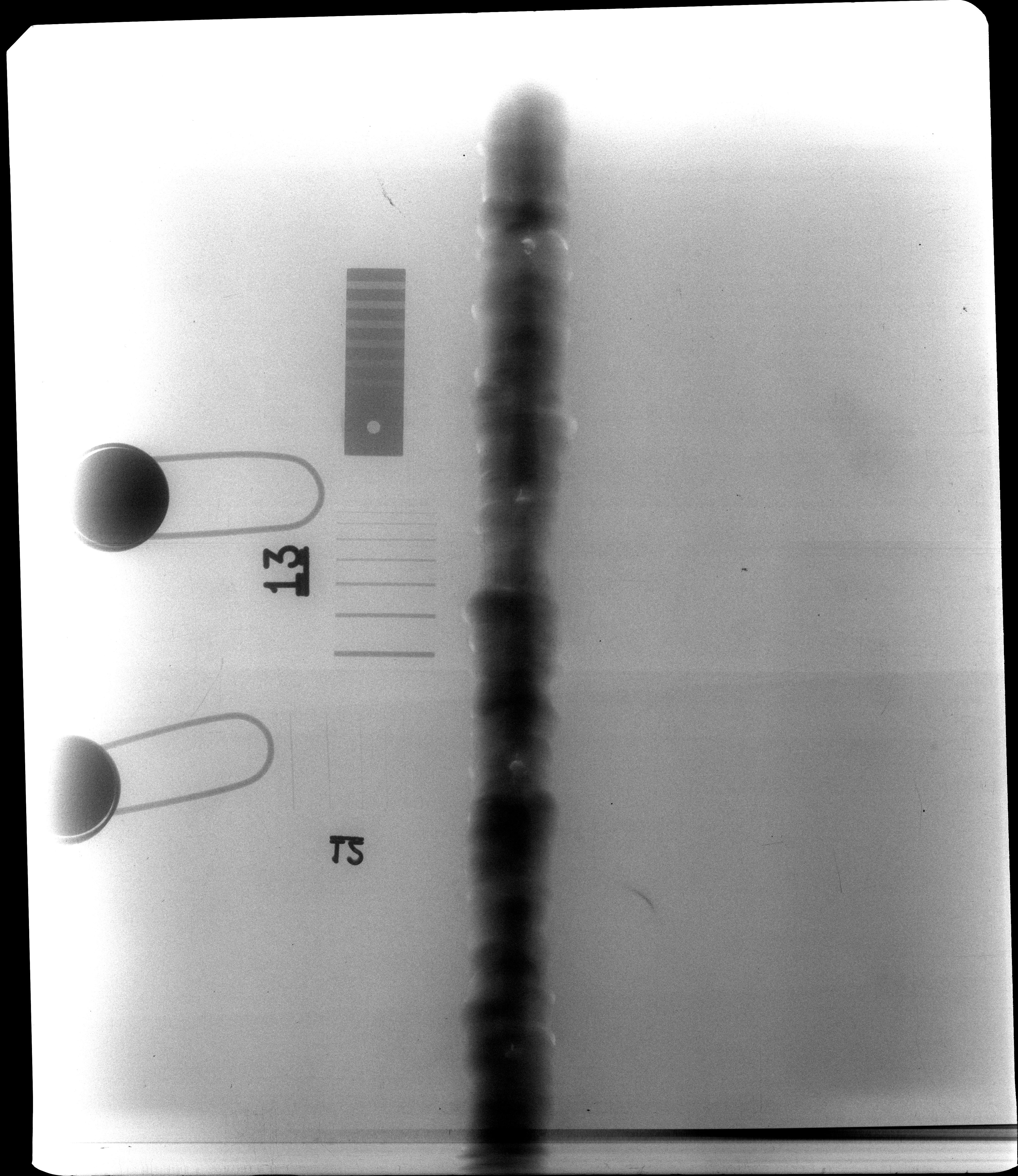
Рисунок Б.1 - Изображение металлической пластины со швом стыкового соединения, просвеченное рентгеновским аппаратом РАП-160 с параметрами просвечивания
U=120 кВ, I=4,5 мА, T=30 с на 1 метре (запоминающая пластина Фуджи)
Приложение В
(обязательное)
The Radiographic Process
Section 2
Студент гр.1540 _______________ С.А. Будкеева
_______________
Консультант кафедры ФМПК
доцент _______________ П.В. Ефимов
_______________
Консультант – лингвист МКПИЯ
доцент _______________ Г.А. Венюкова
_______________
В.1 Radiographic Process
B.1.1 Nature of X-Rays
X-ray is a form of electromagnetic radiation (EMR), the same as light. Its distinguishing feature is its extremely short wavelength--only about 1/10,000 that of light, or even less. This characteristic is responsible for the ability of x-rays to penetrate materials that absorb or reflect ordinary light.
X-rays exhibit all the properties of light, but in such a different degree as to modify greatly their practical behavior. For example, light is refracted by glass and, consequently, is capable of being focused by a lens in such instruments as cameras, microscopes, telescopes, and spectacles. X-rays are also refracted but the most refined experiments are required to detect this phenomenon. Hence, it is impractical to focus x-rays. It would be possible to illustrate the other similarities between x-rays and light but, for the most part, the effects produced are so different and it is preferable to consider x-rays and gamma rays separately from other radiations. The figure В.1 below shows their location in the electromagnetic spectrum.
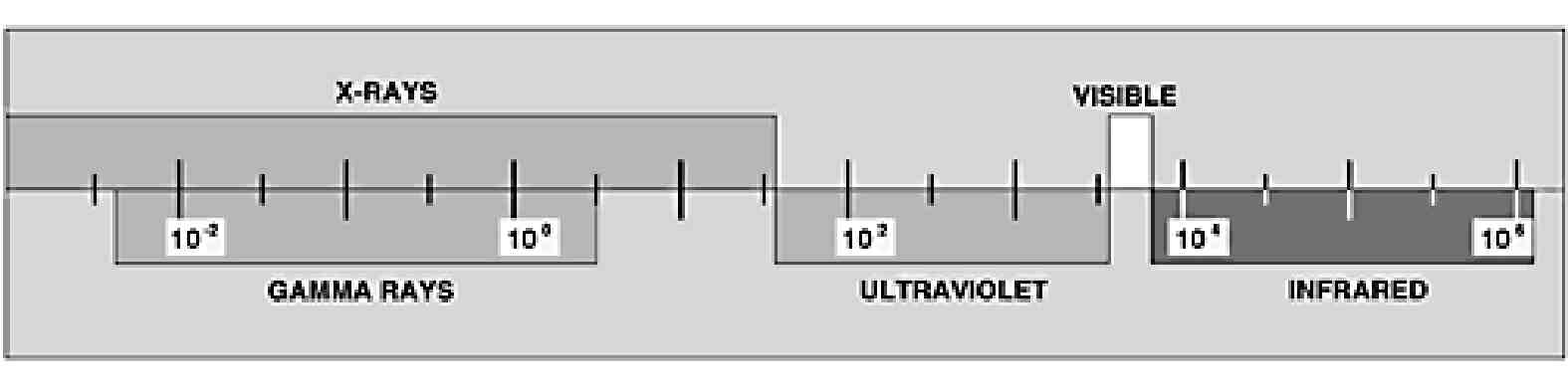
Figure В.1 - Portion of the electromagnetic spectrum. Wavelengths in angstrom units (1A = 10-8 cm = 3.937 x 10⁻⁹ inch)
B.1.2 Nature of Gamma Rays
Gamma rays are similar in their characteristics to x-rays and show the same similarities to, and differences from, visible light as do x-rays. They are distinguished from x-rays only by their source, rather than by their nature. Gamma rays are emitted from the disintegrating nuclei of radioactive substances, and the quality (wavelength or penetration) and intensity of the radiation cannot be controlled by the user. Some gamma-ray-emitting radioactive isotopes, such as radium, occur naturally. Others, like cobalt 60, are artificially produced. In industrial radiography, the artificial radioactive isotopes are used almost exclusively as sources of gamma radiation.
В.1.3 Making a Radiograph
A radiograph is a photographic record produced by the passage of x-rays or gamma rays through an object onto a film. See the figure below. When film is exposed to x-rays, gamma rays, or light, an invisible change called a latent image is produced in the film emulsion. The areas so exposed become dark when the film is immersed in a developing solution, the degree of darkening depending on the amount of exposure. After development, the film is rinsed, preferably in a special bath, to stop development. The film is next put into a fixing bath, which dissolves the undarkened portions of the sensitive salt. It is then washed to remove the fixer and dried so that it may be handled, interpreted, and filed. The developing, fixing, and washing of the exposed film may be done either manually or in automated processing equipment.
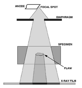
Figure В.2 - Schematic diagram showing the fundamentals of a radiographic exposure. The dark region of the film represents the more penetrable part of an object; the light regions - the more opaque
The diagram in figure В.3 shows the essential features in the exposure of a radiograph. The focal spot is a small area in the x-ray tube from which the radiation emanates. In gamma radiography, it is the capsule containing the radioactive material, for example, cobalt 60, that is the source of radiation. In either case the radiation proceeds in straight lines to the object; some of the rays pass through and others are absorbed, the amount transmitted depending on the nature of the material and its thickness. For example, if an object is a steel casting having a void formed by a gas bubble, the void results in a reduction of the total thickness of steel to be penetrated. Hence, more radiation will pass through the section containing the void than through the surrounding metal. A dark spot, corresponding to the projected position of the void, will appear on the film when it is developed. Thus, a radiograph is a kind of shadow picture--the darker regions on the film representing the more penetrable parts of the object, and the lighter regions, those more opaque to x- or gamma-radiation.
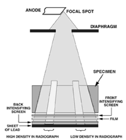
Figure В.3 - Diagram of setup for making an industrial radiograph
with x-rays
В.1.4 Intensifying Screens
X-ray and other photographic films are sensitive to the direct action of the x-rays, but the photographic effect can be increased very appreciably, and exposure time can be decreased by the use of an intensifying screen in contact with each side of the film.
One form of intensifying screen consists of lead foil, or a thin layer of a lead compound evenly coated on a paper backing. Under the excitation of x-rays of short wavelength and gamma rays, lead is a good emitter of electrons which expose the sensitive film thus increasing the total photographic effect.
Another form of intensifying the screen consists of a powdered fluorescent chemical--for example, calcium tungstate, mixed with a suitable binder and coated on cardboard or plastic. Its action depends on the fact that it converts some of the x-ray energy into light to which the film is very sensitive.
The decision as to the type of screen to be used or whether a screen is to be used at all depends on a variety of circumstances which will be discussed in more detail later.
В.1.5 Scattered Radiation
It is a property of all materials not only to absorb and transmit x-rays and gamma rays in varying degrees, but also to scatter them as radiation of longer wavelength in all directions. In radiography, the film receives scattered radiation from an object, the film holder, and any other material in the path of the primary x-ray beam. The effect is to diminish the contrast, detail, and clarity of the radiographic image. Lead screens, in contact with the film, lessen the relative effect of this longer-wavelength scattered radiation. Under some circumstances, a filter of copper or lead, placed between the x-ray tube and the object, or between the object and the film, diminishes the effect of scattered radiation on the film. A lead mask that limits the volume of matter exposed to the primary radiation is sometimes helpful in lessening the scatter.
В.1.6 Types of Film
Several special types of x-ray film have been designed for the radiography of materials. Some types work best with lead screens, or without screens. Other types are intended primarily for use with fluorescent intensifying screens. X-ray films are commonly coated with emulsion on both sides of the support. The superposition of the radiographic images of the two emulsion layers doubles the density and hence greatly increases the speed. X-ray films coated on one side only (single-coated films) are available for use when the superposed images in two emulsions might cause confusion.
В.2 Geometric Principles
A radiograph is a shadow picture of an object that has been placed in the path of an x-ray or gamma-ray beam, between the tube anode and the film or between the source of gamma radiation and the film. It naturally follows, therefore, that the appearance of an image thus recorded is materially influenced by the relative positions of the object and the film and by the direction of the beam. For these reasons, familiarity with the elementary principles of shadow formation is important to those making and interpreting radiographs.
В.2.1 General Principles
Since x-rays and gamma rays obey the common laws of light, their shadow formation may be explained in a simple manner in terms of light. It should be borne in mind that the analogy between light and these radiations is not perfect since all objects are, to a greater or lesser degree, transparent to x-rays and gamma rays and since scattering presents greater problems in radiography than in optics. However, the same geometric laws of shadow formation hold for both light and penetrating radiation.
The law governing the size of the shadow may be stated:
The diameter of an object is related to the diameter of the shadow as the distance of the light from the object is related to the distance of the light from the card.
Mathematically, the degree of enlargement may be calculated by following equations:
![]()
where SO is the size of an object; Si is the size of the shadow (or the radiographic image); D0 is the distance from the source of radiation to object; and Di is the distance from the source of radiation to the recording surface (or radiographic film).
The degree of sharpness of any shadow depends on the size of the source of light and on the position of an object between the light and the card whether nearer to or farther from one or the other. When the source of light is not a point but a small area, the shadows cast are not perfectly sharp because each point in the source of light casts its own shadow of an object, and each of these overlapping shadows is slightly displaced from the others, producing an ill-defined image.
The form of the shadow may also differ according to the angle that the object makes with the incident light rays. Deviations from the true shape of the object as exhibited in its shadow image are referred to as distortion.
В.2.2 Radiographic Shadows
The basic principles of shadow formation must be given primary consideration in order to assure satisfactory sharpness in the radiographic image and essential freedom from distortion. A certain degree of distortion naturally will exist in every radiograph because some parts will always be farther from the film than others, the greatest magnification being evident in the images of those parts at the greatest distance from the recording surface.
In Figure В.4 the two circular objects can be rendered either as two circles (See Figure В.4A) or as a figure-eight-shaped shadow (See Figure В.4B). It should be observed that both lobes of the figure eight have circular outlines.

Figure В.4 - Two circular objects can be rendered as two separate circles (A) or as two overlapping circles (B), depending on the direction of the radiation.
В.2.3 Application
The application of the geometric principles of shadow formation of radiography leads to five general rules. Although these rules are stated in terms of radiography with x-rays, they also apply to gamma-ray radiography.
1. The focal spot should be as small as other considerations will allow, for there is a definite relation between the size of the focal spot of the x-ray tube and the definition in the radiograph. A large-focus tube although capable of withstanding large loads does not permit the delineation of as much detail as a small-focus tube. Long source-film distances will aid in showing detail when a large-focus tube is employed, but it is advantageous to use the smallest focal spot permissible for the exposures required.
The distance between the anode and the material examined should always be as great as in practice. Comparatively long-source distances should be used in the radiography of thick materials to minimize the fact that structures farthest from the film are less sharply recorded than those nearer to it. At long distances, radiographic definition is improved and the image is more nearly the actual size of an object.
The film should be as close as possible to the object being radiographed. In practice, the film in its cassette or exposure holder is placed in contact with the object.
4. The central ray should be as nearly perpendicular to the film as possible to preserve spatial relations.
As far as the shape of the specimen will allow, the plane of maximum interest should be parallel to the plane of the film.
В.3 Radiographic Screens
Another factor governing the photographic density of the radiograph is the intensifying action of the screens used. Intensifying screens and lead screens are fully discussed in "Radiographic Screens". It will suffice to state here that x-rays and gamma rays cause fluorescent intensifying screens to emit light that may materially lessen the exposure necessary to produce a given density. Lead screens emit electrons under the action of x-rays and gamma rays. The photographic effect of these electrons may permit a shorter exposure than would be required without lead screens.
В.3.1 Exposure Factor
The "exposure factor" is a quantity that combines milliamperage (x-rays) or source strength (gamma rays), time, and distance. Numerically the exposure factor equals:

Radiographic techniques are sometimes given in terms of kilovoltage and exposure factor, or radioactive isotope and exposure factor. In such a case, it is necessary to multiply the exposure factor by the square of the distance to be used in order to find, for example, the milliampere-minutes or the curie-hours required.
В.3.2 Determination of Exposure Factors
X-rays
The focus-film distance is easy to establish by actual measurement; the milliamperage can conveniently be determined by the milliammeter supplied with the x-ray machine; and the exposure time can be accurately controlled by a good time-switch. The tube voltage, however, is difficult and inconvenient to measure accurately. Furthermore, designs of individual machines differ widely, and may give x-ray outputs of a different quality and intensity even when operated at the same nominal values of peak kilovoltage and milliamperage.
Consequently, although specified exposure techniques can be duplicated satisfactorily in the factors of focus-film distance, milliamperage, end exposure time, one apparatus may differ materially from another in the kilovoltage setting necessary to produce the same radiographic density. Because of this, the kilovoltage setting for a given technique should be determined by trial on each x-ray generator. In the preliminary tests, published exposure charts may be followed as an approximate guide. It is customary for equipment manufacturers to calibrate x-ray machines at the factory and to furnish suitable exposure charts. For the unusual problems that arise, it is desirable to record all the data on exposure and techniques in a logbook. In this way, operators will soon build up a source of information that will make them more competent to deal with difficult situations.
For developing trial exposures, a standardized technique should always be used. If this is done, any variation in the quality of the trial radiographs may then be attributed to the exposure alone. This method obviates many of the variable factors common to radiographic work.
Since an increase of kilovoltage produces a marked increase in x-ray output and penetration, it is necessary to maintain a close control of this factor in order to secure radiographs of uniform density. In many types of industrial radiography where it is desirable to maintain constant exposure conditions with regard to focus-film distance, milliamperage, and exposure time, it is common practice to vary the kilovoltage in accordance with the thickness of the material to be examined so as to secure proper density in the radiographic image. Suppose, for example, it is desired to change from radiographing 11/2-inch steel to radiographing 2-inch steel. The 2-inch steel will require more than 10 times the exposure in milliampere-minutes at 170 kilovolts. However, increasing the kilovoltage to a little more than 200 will yield a comparable radiograph with the same milliampere-minutes Thus, kilovoltage is an important variable because economic considerations often require that exposure times be kept within fairly narrow limits. It is desirable, as a rule, to use as low a kilvoltage as other factors will permit. In the case of certain high-voltage x-ray machines, the technique of choosing exposure conditions may be somewhat modified. For instance, the kilovoltage may be fixed rather than adjustable at the will of the operator, leaving only milliamperage, exposure time, film type, and focus-film distance as variables.
Gamma Rays
With radioactive materials, the variable factors are more limited than with x-rays. Not only is the quality of the radiation fixed by the nature of the emitter, but also the intensity is fixed by the amount of radioactive material in the particular source. The only variables under the control of operators, and the only quantities they need to determine, are the source-film distance, film type, and the exposure time. As in the case of x-radiography, it is desirable to develop trial exposures using the gamma-ray sources under standardized conditions and to record all data on exposures and techniques.
В.3.3 Contrast
In a radiograph, the various intensities transmitted by the specimen are rendered as different densities in the image. The density differences from one area to another constitute radiographic contrast. Any shadow or detail within the image is visible by reason of the contrast between it and its background of surrounding structures. Within appropriate limits, the greater the contrast or density differences in the radiograph, the more definitely various details will stand out. However, if overall contrast is increased too much, there is an actual loss in visibility of detail in both the thick and the thin regions of the specimen. The thick sections will be imaged at densities too low to be useful and the thin sections, at densities too high to be viewed on the available illuminators. This principle is fully illustrated in Figure В.5, which shows two radiographs of a steel stepped wedge, one (A) exposed at a high tube voltage and the other (B) at a low voltage. It is apparent that in the middle tones the differentiation in the steps is greater in the low-voltage radiograph (B) than in the high-voltage radiograph (A). Near the end, however, the steps shown in A are much less apparent in B.

Figure В.5 - A: 220 kV exposure. B: 120 kV exposure. Radiographs of stell stepped wedge having a thickness range of 1/4 to 3/4 inch in 1/8-inch steps.
Radiographic contrast is a result of both subject contrast and film contrast. Subject contrast is governed by the range of radiation intensities transmitted by the specimen. A flat sheet of homogeneous material of nearly uniform thickness would have very low subject contrast. Conversely, a specimen with large variations in thickness which transmits a wide range of intensities, would have high subject contrast. Overall subject contrast could be defined as the ratio of the highest to the lowest radiation intensities falling on the film. Contrast is also affected by scattered radiation, removal of which increases subject contrast.
В.3.4 Choice Of Film
Different films have different contrast characteristics. Thus, a film of high contrast may give a radiograph of relatively low contrast if the subject contrast is very low; conversely, a film of low contrast may give a radiograph of relatively high contrast if the subject contrast is very high. With any given specimen, the contrast of the radiograph will depend on the kilovoltage of the x-rays or the quality of the gamma rays (See Figure В.5), the contrast characteristic of the film, the type of screen, the density to which the radiograph is exposed, and the processing.
В.3.5 Radiographic Sensitivity
In the radiography of materials of approximately uniform thickness, where the range of transmitted x-ray intensities is small, a technique producing high contrast will satisfactorily render all portions of the area of interest, and the radiographic sensitivity1 will be greater than with a technique producing low contrast. If, however, the part radiographed transmits a wide range of x-ray intensities, then a technique producing lower contrast may be necessary in order to record detail in all portions of radiographic sensitivity. (See Figure В.6.)
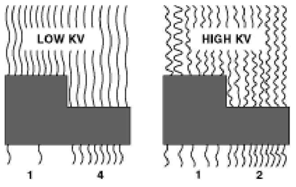
Figure В.6 - As kilovoltage increases, subject contrast decreases because more wavelengths penetrate the subject in both thick and thin sections, thus reducing the overall difference in exposure between the two
В.3.6 Effects Of Processing
Film contrast increases with the degree of development up to a limit determined by the properties of both the film and the developer. For manual development, the development time should not be less than the minimum time recommended for the film-developer combination. Some films may be developed longer than this minimum time to obtain higher speed.
In automated processing, the recommended operating conditions of the processing machine are such that the maximum film contrast is obtained.
Radiographs of high contrast are likely to contain areas of high density in which detail cannot he seen with ordinary illumination. High-intensity illuminators, for viewing radiographs of high density, are commercially available.
"Radiographic sensitivity" refers to the size of the smallest detail that can be seen in a radiograph or to the ease with which the images of small details can be detected. In comparing radiographs of the same specimen, the one that renders details most clearly visible is said to have the highest radiographic sensitivity.
В. 4 Arithmetic of Exposure
Relations of Milliamperage (Source Strength), Distance and Time
With a given kilovoltage of x-radiation or with the gamma radiation from a particular isotope, the three factors governing the exposure are the milliamperage (for x-rays) or source strength (for gamma rays), time, and source-film distance. The numerical relations among these three quantities are demonstrated below using x-rays as an example. The same relations apply for gamma rays, provided the number of curies in the source is substituted wherever milliamperage appears in an equation.
The necessary calculations for any changes in focus-film distance (D), milliamperage (M), or time (T) are matters of simple arithmetic and are illustrated in the following example. As noted earlier, kilovoltage changes cannot be calculated directly but must be obtained from the exposure chart of the equipment or the operator's logbook.
All of the equations shown on these pages can be solved easily for any of the variables (mA, T, D) using one basic rule of mathematics: If one factor is moved across the equals sign (=), it moves from the numerator to the denominator or vice versa.
We can now solve for any unknown by:
Eliminating any factor that remains constant (has the same value and is in the same location on both sides of the equation).
Simplifying the equation by moving the unknown value so that it is alone on one side of the equation in the numerator.
Substituting the known values and solving the equation.
Milliamperage-Distance Relation
The milliamperage employed in any exposure technique should be in conformity with the manufacturer rating of the x-ray tube. In most laboratories, however, a constant value of milliamperage is usually adopted for convenience.
Time-Distance Relation
Rule: The exposure time (T) required for a given exposure is directly proportional to the square of the focus-film distance (D).
The factor between the new and the old exposure time, milliamperage, or milliamperage-minute (mA-min) value appears in the box at the intersection of the column for the new source-film distance and the row for the old source-film distance.
Suppose, for example, a properly exposed radiograph has an exposure of 20 mA-min with a source-film distance of 30 inches and you want to increase the source-film distance to 45 inches in order to decrease the geometric unsharpness in the radiograph. The factor appearing in the box at the intersection of the column for 45 inches (new source-film distance) and the row for 30 inches (old source-film distance) is 2.3. Multiply the old milliampere-minute value (20) by 2.3 to give the new value--46 mA-min.
Note that some approximation is involved in the use of such a table, since the values in the boxes are rounded off to two significant figures.
However, the errors involved are always less than 5 percent and, in general, are insignificant in actual practice.
Further, a table like Table V obviously cannot include all source-film distances, because of limitations of space. However, in any one radiographic department, only a few source-film distances are used in the great bulk of the work, and a table of reasonable size can be constructed involving only these few distances.
Milliamperage-Time Relation
Rule: The milliamperage (M) required for a given exposure is inversely proportional to the time(T):
Another way of expressing this is to say that for a given set of conditions (voltage, distance, etc), the product of milliamperage and time is constant for the same photographic effect.
Thus, M1T1 = M2T2 = M3T3 = C, a constant.
This is commonly referred to as the reciprocity law. (Important exceptions are discussed below.)
To solve for either a new time (T2) or a new milliamperage (M2), simply follow the steps shown in the example in "Milliamperage-Distance Relation".
Conclusion
Radiography today is one of the most important, most versatile, of all the nondestructive test methods used by modern industry. Employing highly penetrating x-rays, gamma rays, and other forms of radiation that do not damage the part itself, radiography provides a permanent visible film record of internal conditions, containing the basic information by which soundness can be determined. In the past decade alone, the evidence from millions of film records, or radiographs, has enabled industry to assure product reliability; has provided the informational means of preventing accidents and saving lives; and has been beneficial for the user.
Since economic justification is a major criterion for any testing method, the value of radiography lies to some extent in its ability to make a profit for its user. This value is apparent in machining operations where only pieces known to be sound are permitted on the production lines. It is equally apparent in cost reductions when less expensive materials or fabricating methods can be employed instead of costlier ones in which soundness is only an estimated quality. The information gained from the use of radiography also assists the engineer in designing better products and protects the company by maintaining a uniform, high level of quality in its products. In total, these advantages can help to provide customer satisfaction and promote the manufacturers reputation for excellence.