

dimensionality of these vectors and S-matrices is determine by the general number of waveguide types, which are allowed for in the process of recomposition.
The complex-amplitude vectors A±k are related by three matrix equations, which include the matrix SB. Four additional matrix equations with the channel-filter matrices SFi will be obtained for the vectors B±k and C±k . Excluding the vectors A±2 , A±3 , B±2 , and B±3 from the obtained system of equations, we find formulas for the multimode diplexers scattering matrix.
4.NUMERICAL RESULTS
The proposed hybrid method of electrodynamic analysis of diplexers is characterized by high e ciency due to the choice of the most e cient methods corresponding to specific features of these subproblems. For example, the Galerkin method allowing for the edge singularity ensures five correct significant digits in the process of calculating critical frequencies of edge waveguides if one uses only three or four basic functions in expansions (1) and (3) (N = 3 or 4). The e ciency of the mode matching method and the method of generalized scattering matrices for analysis of waveguide devices is also well known. In the case under consideration, up to 20 higher modes of each type were allowed for in the process of recomposition of the S-matrices. Comparison of the obtained results with the theoretical and experimental data [6], as well as with the results obtained by the finite-element method (FEM) [9], demonstrates good coincidence of the results (Figs. 4 and 5), which confirms high accuracy of the presented calculation method. In this case, the time of calculations using the proposed algorithm is more than an order of magnitude shorter than the time of FEM-based calculations [9].
When the optimal design of the filters is sought for, the well-developed methods of radiotechnical synthesis can be used at the first step to determine their initial form [10, 11]. These methods are based on the circuit theory and yield an approximate, relatively rough estimate of the characteristics of a real waveguide structures. The second way, which is realized in this work, consists in the use of a fast electrodynamic analysis algorithm and the available practical experience of interactive synthesis of the initial filter form. At the following stage, the final multi-parameter optimization of the filters is performed on the basis of the developed electrodynamic algorithm. The objective function of the following form was used for multiparameter optimization of bandpass filters:
N1 |
N1+N2 |
F (¯x) = α1 [S11 P − S11(fi)]2 + α2 |
[S21 S − S21(fi)]2 , |
i=1 |
i=N1+1 |
where S11 P and S21 S are set values, the function S21(fi) determines the calculated level of the insertion loss at the frequency fi, and α1 and α2 are weighting factors. When calculating the value of the objective function, the number of frequency points in the transmission band was usually specified as N1 = 10–20 in the pass band and N2 = 5, in the upper stepband. The vector of varied parameters x¯ = (li, ri, di) included longitudinal dimensions of ridge resonators and inductive strips, as well as the distance between them (see Fig. 1). To find the minimum of the objective function, we used the method of direct pattern search [12], which ensures su ciently fast localization of the extremum of the objective function for the given class of problems.
At the first stage, characteristics of two channel filters of the diplexer (Fig. 4) and the matching step-wise transition with a waveguide junction were optimized separately. The final optimization of the diplexer was peformed by varying the parameters of the step-wise transition and position of the filters in the channels of the diplexer with the objective function being similar to that used in [1].
Figures 4 and 5 show the characteristics of optimized design versions of the filters and diplexers operated in the centimeter wavelength band (K-band) shown in Fig. 1 (the corresponding dimensions are shown in Fig. 1). As is seen in Fig. 4, such design of the filters ensures a frequency characteristic with symmetric slopes, a wide stop band, and a high level of attenuation in it, which is significant for their application as elements of diplexers and multiplexers.
306
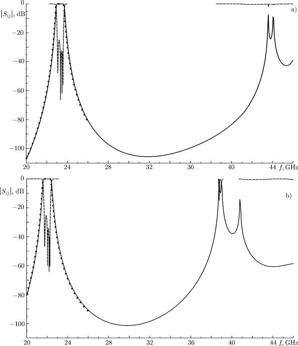
Fig. 4. Frequency characteristics of filters 1 and 2 (a and b in Fig. 1, respectively). The solid and dashed lines correspond to |S21| and |S11|, respectively. The symbols show the results obtained by the finite-element method [9].
The diplexer is based on five-resonator filters (Fig. 1). It performs frequency multiplexing of the reception and transmission lines operated in the bands 21.75–22.3 GHz and 23.05–23.6 GHz, which corresponds to a filter passband of 2.5%. The absolute value of the reflection coe cient within the passbands is not lower than 25 dB. The decoupling of the diplexer channels is at least 46 dB. The longitudinal size of the diplexer is about 52 mm, which is approximately 1.5 times lower compared with the filter analog based on the E-plane longitudinal inductive diaphragms [1].
307
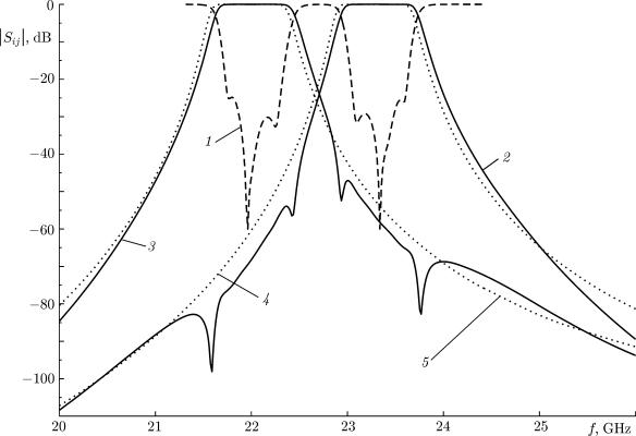
Fig. 5. Frequency characteristics of a K-band diplexer (see Fig. 1; the dimensions are presented in Table 1). Curves 1, 2, and 3 correspond to |S11|, |S21|, and |S31|, respectively. The dashed lines show the characteristics of filters 1 and 2 (curves 4 and 5, respectively) calculated by the finite-element method [9].
TABLE 1. Geometric dimensions of the diplexer shown in Fig. 1. The dimensions of the input and evanescent waveguides are 11 × 5.5 mm and 6 × 5.5, respectively, and the foil is 0.2 mm thick.
T-junction |
|
|
Filter 1 (channel 2) |
Filter 2 (channel 3) |
|
|
|
|
|
|
|
b = 5.5 mm |
c1 |
= 10.069 mm |
li = 3.205; 1.205; 1.838 mm |
li = 2.410; 1.039; 1.478 mm |
|
b1 |
= 7.372 mm |
c2 |
= 0.739 mm |
ri = 2.046; 2.820; 2.390 mm |
ri = 2.807; 3.835; 3.444 mm |
b2 |
= 12 mm |
c3 |
= 6.236 mm |
di = 0.865; 0.846 mm |
di = 0.705; 0.782 mm |
d = 1 mm |
c4 |
= 8.023 mm |
w2 = 2.0 mm |
w3 = 1.868 mm |
|
|
|
|
|
Lf = 34.126 mm |
Lf = 34.59 mm |
5.CONCLUSIONS
We propose a new small-size and technological design of a waveguide diplexer for operation in the centimeter and millimeter wavelength bands. The diplexer is based on the E-plane waveguide T-junction and filters with ridge resonators and longitudinal inductive diaphragms. Both filters are implemented on one thin metal-foil inset, which is located in the E-plane of the waveguide.
An e ective hybrid electrodynamic method of analyzing this class of diplexers is proposed, which is based on the Galerkin method allowing for the edge singularity of the field, the mode matching method, and the method of generalized scattering matrices. Characteristics of the optimized design version of a K-band diplexer are presented. The dimensions of this diplexer 1.5 times smaller than the known counterparts based on the longitudinal E-plane ribbon diaphragms.
308
REFERENCES
1. J. Dittlo and F. Arndt, IEEE Trans. Microwave Theory and Tech., MTT-37, No. 2, 340 (1989).
2.A. Morini, T. Rozzi, and D. Angelis, IEEE MTT–S Intern. Microwave Symposium Digest. 14–18 June 1993, Atlanta, GA, USA, p. 1077.
3.M. B. Manuilov and G. P. Sinyavskii, J. Commun. Tech. Electron., 46, No. 2, 127 (2001).
4.G. P. Sinyavsky, M. B. Manuilov, and K. V. Kobrin, Usp. Sovr. Radio´elektron., No. 4, 5 (2006).
5. E. Ofli, R. Vahldieck, and S. Amari, IEEE Trans. Microwave Theory and Techn., 53, No. 3, 843 (2005).
6.A. Kirilenko, L. Rud, V. Tkachenko, and D. Kulik, IEEE Trans. Microwave Theory and Tech., MTT50, No. 5, 1324 (2002).
7.M. B. Manuilov, K. V. Kobrin, G. P. Sinyavsky, and O. S. Labunko, Proc. Progress Electromagn. Res. Symp. (PIERS 2009). Moscow, 18–21 August 2009, p. 1393.
8.J. Bornemann and F. Arndt, IEEE Trans. Microw. Theory and Tech., MTT-35, No. 6, 561 (1987).
9.Ansys HFSS: http://www.ansys.com .
10.J. -Ch. Nanan, J. -W. Tao, H. Baudrand, et al., IEEE Trans. Microwave Theory and Tech., 39, No. 12, 2192 (1991).
11.G. Matthaei, L. Young, and E. M. T. Jones, Microwave Filters, Impedance-Matching Networks, and Coupling Structures, McGraw Hill, New York (1964).
12. K. C. Gupta, R. Garg, and R. Chadha, Computer-Aided Design of Microwave Circuits, Artech House (1981).
309