

requirement for the miniaturization of microwave components is no exception. Conventional planar transmission-line circuits cannot reduce the guide wavelength by more than the factor of ' r Žwhere r is the relative permittivity of the substrate. from the free-space wavelength. A reduction in size requires a change in geometry of the microwave component; the simplest, for example, may be moving from a waveguide to a microstrip. More complex and novel changes in geometry may be required for the ultimate in miniaturization. Consequently, in order to reduce the size, weight, and cost, there has been a growing interest in planar structures. Provided the performance is appropriate for the application, miniature filters are useful in many applications, especially in the aerospace industry. Therefore, microstrip open-loop resonators ŽMOLRs. have been used for cross-coupled planar microwave filter applications 1 . Also, Hong and Lancaster have described a microstrip slow-wave OLR, and have introduced a new class of microstrip bandpass filters based on coupled slow-wave OLRs 2 . After that, Yu and Chang 3 proposed compact elliptic-function narrowband bandpass filters using MOLRs. However, according to our knowledge, the effect of the width of the strips of an MOLR on its resonance characteristics has not been discussed in the microwave literature.
In this paper, we investigate the influence of the variation in the width of a longer strip of the microstrip loop on the resonance characteristics of the MOLR. The microstrip open-loop resonator is formed by cutting a gap in the middle of the one of longer strips of the microstrip loop, which is obtained by removing the entire area inside the center conductor of a conventional microstrip. Such a transmission line can also be a possible solution as a slow-wave structure.
2. STANDARD MICROSTRIP LOOP RESONATOR
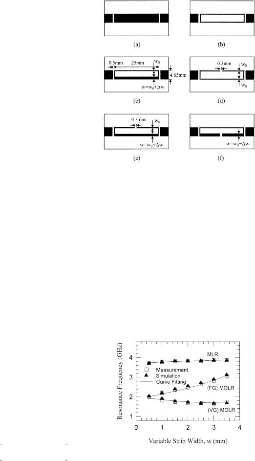
A standard microstrip loop resonator ŽSMLR; all strips of the loop have the same width. can be realized by keeping the same occupied surface area when the internal part of the signal strip of a conventional microstrip Fig. 1Ža. is taken off, as shown in Figure 1Žb.. The resonance frequency of the SMLR does not significantly change from that of the conventional half-wavelength microstrip resonator, as confirmed by our experiments. However, the widths of longer strips of the MLR may be different, as shown in Figure 1Žc.. Namely, if one of the loop strips oriented along the direction of propagation is extended wider than the other strip, then a so-called variable strip MLR ŽVS MLR. is obtained. First, for convenience of comparison, the resonance frequency of the SMLR Ž w 0. has been measured by keeping all of its strip widths at the same size. Then, the width of one of the longer strips oriented along the direction of propagation has been changed, keeping the same occupied surface area. The measured resonance frequency of these resonators, as well as simulated results, as a function of the width wŽ w0 w. is shown in Figure 2. A full-wave EM simulator 4 was used to simulate the resonance frequency of novel resonators. Moreover, it may be convenient to estimate the resonance frequencies of loop resonators using some closed formulas for designing the VS MLR. So, the results Žsolid line. obtained using a closedform expression, derived by fitting the experimental results, are also presented in the figure. This closed-form expression is
f0 |
ŽGHz. f0 Ž r |
. |
0.99 |
0.37 F Ž w, w0 . |
|
Ž1. |
||
|
3 |
F Ž w, w0 . |
||||||
|
|
|
2 |
|
||||
Figure 1 Conventional and novel half-wavelength microstrip resonators fabricated on the same surface area. Ža. Conventional microstrip. Žb. Standard microstrip loop ŽSMLR.. Žc. Signal strip of variable-strip microstrip loop ŽVS MLR.. Žd. Signal strip of standard microstrip open-loop ŽS. MOLR . Že. Signal strip of fixed-gap openloop ŽFG. MOLR . Žf. Signal strip of variable-gap open-loop ŽVG. MOLR
where f0Ž r . is the measured fundamental resonance frequency Žin gigahertz. of the resonator in the case of w 0 for the dielectric substrate of interest, and FŽ w, w0. is given by
F Ž w, w0 |
. |
w0 w |
. |
Ž2. |
|
||||
|
|
16 w0 |
|
|
3. MICROSTRIP OPEN-LOOP RESONATOR
If we cut a gap into the one of the longer strips, oriented along the direction of propagation, of the standard loop, a so-called microstrip open-loop resonator ŽMOLR. is formed, as shown in Figure 1Žd.. It can be expected that the funda-
Figure 2 Fundamental resonance frequency as a function of variable strip width
178 MICROWAVE AND OPTICAL TECHNOLOGY LETTERS / Vol. 31, No. 3, November 5 2001
mental resonance frequency of the novel resonator will be almost half that of a corresponding SMLR because the mean length of an OLR in the present study is about twice that of the associated MLR. This novel resonator can be constructed in two ways, as shown in Figure 1Že. and Žf., in order to observe the influence of the variation w in a longer strip width of the open loop on the resonance characteristics. To simplify our description, the two structures are called the fixed-gap ŽFG. MOLR see Fig. 1Že. and the variable-gap ŽVG. MOLR see Fig. 1Žf. . All of the resonators are fabricated on RT Duroid 5870 substrates, with a relative permittivity of 2.33 and a thickness of 1.575 mm.
Figure 2 shows the experimental resonance frequency of the ŽFG. MOLR structures as a function of the strip width w. The fundamental resonance frequency increases from minimum resonance frequency in the case of w 0 to maximum resonance frequency in the case of w 3 mm as the strip width is increased. The curve-fitting results as well as simulated results are also given in the figure, which are derived by using the formula
f0 |
ŽGHz. f0 Ž r |
. |
0.88 |
|
F Ž w, w0 . |
. Ž3. |
|
|
2 |
|
|||||
|
|
|
1 |
Ž F Ž w, w0 . . |
|
||
It is apparent from the graphs that the resonance frequency will approach those of the conventional microstrip resonator loaded with a transverse narrow slit when the width of the associated strip is further increased.
In the case of a ŽVG. MOLR, the mean circumference of the resonator does not decrease with increased w in the strip width because, in this case, both the inner side and the outer side of the coupling gap support the coupling in the loop gap. In these structures, the width of the variable strip is changed from 0.5 to 3.5 mm. It should be noted that the fundamental resonance frequency is decreased as the width of the variable strip is increased. However, the resonance frequency drops to its minimum value at a strip width of 3.0 mm, and then it rises again. This may be more clearly seen from the variation of both the measured and the simulated resonance frequency with the strip width in Figure 2. It should be noted that the strip width of 2.5 mm is about the half width of the signal strip of a conventional microstrip. The curve-fitting results are calculated using the expression
f0 ŽGHz. 0.765 f0 Ž r .
ŽŽ1 F Ž w, w0 . .2 2.75 F Ž w, w0 . . . Ž4.
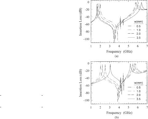
On the other hand, in order to reduce interference by keeping out-of-band signals from reaching a sensitive receiver, a wider upper stopband including the first spurious passband may be required. Figure 3Ža. shows the simulated wideband frequency response of a ŽVG. MOLR for w 0.5, 1.0, 2.0, and 3.5 mm. Increasing the variable strip width increases the separation between the fundamental and the second spurious resonances. The bandwidth between these two resonances is about 4.75 GHz for w 3.5 mm, while it is about 3.75 GHz for w 0.5 mm. The wideband frequency response of an ŽFG. MOLR is also illustrated in Figure 3Žb.. Unlike the ŽVG. MOLR, this configuration supports a decrease in the upper stopband, including the first spurious resonance frequency as the variable strip width is increased. The bandwidth between the fundamental and the second spurious
Figure 3 Simulated wideband response of Ža. ŽVG. MOLR and Žb. ŽFG. MOLR for r 2.33 and h 1.575 mm
resonances is about 1.15 GHz for w 3.5 mm, while it is about 3.75 GHz for w 0.5 mm. Moreover, increasing the variable strip width w also decreases the insertion loss at the first spurious resonance frequency. However, a comparison of simulated and measured frequency characteristics of novel resonators is shown in Figure 4. The separation between the fundamental and the first spurious resonance frequencies is increased for the ŽVG. MOLR when the width of the variable strip is increased, but it is decreased for the ŽFG. MOLR. Also, the insertion loss of the ŽVG. MOLR at the first spurious resonance is increased with an increase in the strip width. An insertion loss at the first spurious resonance frequency of about 4.5 GHz in the case of w 3.5 mm is higher than that at the first spurious resonance frequency of about 4.2 GHz in the case of w 0.5 mm. Thus, the ŽVG. MOLR structure may be an excellent solution for bandpass filters with a wider upper bandstop as well as a slow-wave effect.
Additionally, the measured Q-factors for a conventional half-wavelength microstrip resonator, standard microstrip open-loop resonator ŽS. MOLR , ŽFG. MOLR, and ŽVG. MOLR with different lengths at about the same resonance frequency have been compared to further reveal the electrical properties of the proposed structures. Figure 5 shows the measurement results for the Q-factors of these resonators, which have, respectively, a length of 63, 31, 45, and 25 mm at a resonance frequency of about 1.68 GHz. Moreover, both the ŽFG. MOLR and ŽVG. MOLR have the same variable strip width of w 3.5 mm. As a result, it has been shown that the ŽVG. MOLR with respect to the other structures has supported the best performance as well as the lowest resonance frequency.
MICROWAVE AND OPTICAL TECHNOLOGY LETTERS / Vol. 31, No. 3, November 5 2001 |
179 |