

Антенны, СВЧ / OC / Должиков / Introduction to Smart Antennas_Balanis
.pdfMOBILE COMMUNICATIONS OVERVIEW 13
FIGURE 2.7: Sectorized antenna system and coverage pattern [20].
antennas and base station equipment become prohibitively expensive for most cell sites [45]. Fig. 2.8 shows a system that employs the 120◦ type of cell sectorization.
In sectoring, capacity is improved while keeping the cell radius unchanged and reducing the D/R ratio. In other words, capacity improvement is achieved by reducing the number of cells and, thus, increasing the frequency reuse. However, in order to accomplish this, it is necessary to reduce the relative interference without decreasing the transmitting power. The co-channel interference in such cellular system is reduced since only two neighboring cells interfere instead
FIGURE 2.8: Sectorized cellular network employing three sectors, each one covering 120◦ field of view.

14 INTRODUCTION TO SMART ANTENNAS
(a) |
(b) |
FIGURE 2.9: Co-channel interference comparison between (a) omnidirectional and (b) sectorized systems.
of six for the omnidirectional case [44, 46] as shown in Fig. 2.9. Increasing the number of sectors in a CDMA system has been a technique useful of increasing the capacity of cell sites [47]. Theoretically, the increase in capacity is proportional to the number of sectors per cell [48]. The penalty for improved signal-to-interference (S/I ) ratio and capacity is an increase in the number of antennas at the base station, and a decrease in trunking efficiency [13, 46] due to channel sectoring at the base station. Trunking efficiency is a measure of the number of users that can be offered service with a particular configuration of fixed number of frequencies.
2.6POWER CONTROL
Power control is a technique whereby the transmit power of a base station or handset is decreased close to the lowest allowable level that permits communication [45]. Due to the logarithmic relationship between the capacity of the wireless link and the signal-to-interference-and-noise ratio (SINR) at the receiver [49], any attempt to increase the data rate by simply transmitting more power is extremely costly. Furthermore, increases in power scales up both the desired signals and their mutual interference [28]. Therefore, once a system has become limited by its own interference, power increase is useless. Since mature systems are designed in a way to achieve maximum capacity, it is the power itself, in the form of interference, that ultimately limits their performance [50]. As a result, power must be carefully controlled and allocated to enable the coexistence of multiple geographically dispersed users operating under various

MOBILE COMMUNICATIONS OVERVIEW 15
conditions [28] and has been a topic of active research. For example, both GSM and CDMA systems use power control on both uplink and downlink. Particularly, CDMA systems require fast and precise power control since many users share the same RF spectrum, and the system capacity is thus highly sensitive to inadequate interference control [45].
2.6.1Spectral Efficiency
Another effective way to improve the data rate is to increase the signal bandwidth along with power increase. However, the radio spectrum is not an abundant resource in the frequencies of interest. Moreover, increasing the signal bandwidth beyond the coherence bandwidth results in frequency selectivity and degradation in the transmission quality. Spectral efficiency, defined as the ratio of capacity per unit bandwidth, measures the ability of a wireless system to deliver information with a given amount of radio spectrum and provides another key metric of the wireless system’s quality. It determines the amount of radio spectrum required to provide a given service (e.g., 10 Kbps voice service or 100 Kbps data service) and the number of base stations required to deliver that service to the end-users. In the latter years of deployment, when subscriber penetration is high, it is, consequently, one of the primary determinants of system economics. Spectral efficiency is measured in units of bits/second per Hertz/cell (b/s/Hz/cell). It determines the total throughput each base station (cell or sector) can support with a given amount of spectrum. The appearance of a “per cell” dimension in measuring spectral efficiency may seem surprising, but the throughput of a particular base station of a cellular network is almost always substantially less than that of a single cell in isolation. This difference is attributed to the self-interference generated in the network.
In a cellular system, the radio communication between a user and a base station generates radio energy that is detectable in places other than the immediate vicinity of the user, the base station and an imaginary line between the two. For other users in the vicinity, this excess energy degrades the radio channel, or makes it completely unusable for conversations. As the user density increases, radio resources are in consequence exhausted eventually. Systems with higher spectral efficiency provide more data throughput (services) with a given amount of spectrum and support more users at a given grade of service before experiencing resource exhaustion. The key benefits of higher spectral efficiencies can be enumerated as follows: higher aggregate capacity (per-cell throughput); higher per-user quality and service levels; higher subscriber density per base station; small spectrum requirements; and lower capital and operational costs in deployment. The spectral efficiency for various systems can be calculated easily using
Spectral Efficiency = |
Channel Throughput |
(2.1) |
Channel Bandwidth . |

16 INTRODUCTION TO SMART ANTENNAS
This simply sums the throughput over a channel in an operating network and divides by the channel bandwidth. To understand spectral efficiency calculations, consider the PCS-1900 (GSM) system which can be parameterized as follows: 200 KHz carriers, 8 time slots per carrier, 13.3 Kbps of user data per slot, effective reuse of 7 (i.e., effectively 7 channel groups at 100 percent network load, or only 1/7th of each channels throughput available per cell). The spectral efficiency is therefore:
Kbps
SE = 8 slots × 13.3 slot /200 KHz/7 cells (2.2) = 0.076 b/s/Hz/cell.
This value of approximately 0.1 b/s/Hz/cell is generally representative of high-mobility 2G and 3G cellular systems, including CDMA systems of all types. It reflects the fact that the classical techniques for increasing spectral efficiency have been exhausted and that new techniques are necessary [45]. Finally, it should be noted that the value of approximately 0.1 b/s/Hz/cell represents a major stumbling block for the delivery of next-generation services. Without substantial increases in spectral efficiency, 3G systems are bound to spectral efficiencies like those of todays 2G systems. In a typical 3G system with a 5 MHz downlink channel block, this translates into a total cell capacity of approximately 500 Kbps for the entire cell. With services advertised in the range of 144–384 Kbps, 1–3 users will completely occupy the cell capacity! This is far from the approximately 250–500 subscribers per cell needed to make the system economically viable, and it underscores the need for new methods to boost spectral efficiency.
2.7MULTIPLE ACCESS SCHEMES
Mobile communications utilize the range of available frequencies in a number of ways, referred to as multiple-access schemes. Some basic schemes are FDMA, TDMA, CDMA, and OFDM.
2.7.1FDMA
In the standard analog frequency division multiple access (FDMA) systems, such as AMPS, the most widely cellular phone system installed in North America, different carrier frequencies are allocated to different users. Individual conversations use communication channels appropriately separated in the frequency domain. In a system using the FDMA scheme, six frequencies are assigned to six users, and six simultaneous calls may be made as shown in Fig. 2.10(a). FDMA systems transmit one voice circuit per channel. Each conversation gets its own, unique, radio channel. The channels are relatively narrow, usually 30 KHz or less, and are defined as either transmit or receive channels. A full duplex conversation requires a transmit and receive

MOBILE COMMUNICATIONS OVERVIEW 17
Frequency Division Multiple Access
Carrier Frequency 1
Carrier Frequency 2
Carrier Frequency 3
Carrier Frequency 4
Carrier Frequency 5
Carrier Frequency 6
(a)
Time Division Multiple Access
TS |
TS |
TS |
1 |
2 |
3 |
TS |
TS |
TS |
1 |
2 |
3 |
Carrier Frequency 1
Carrier Frequency 2
(b)
Code Division Multiple Access
Code 1 |
|
|
Code 2 |
|
|
Code 3 |
Carrier Frequency 1 |
|
Code 4 |
||
|
Code 5
Code 6
(c)
FIGURE 2.10: Channel usage for different multiple access schemes: (a) FDMA; (b) TDMA;
(c) CDMA [40].
channel pair. For example, if a FDMA system had 200 channels, the system can handle 100 simultaneously full duplex conversations (100 channels for transmitting and 100 channels for receiving).
2.7.2TDMA
With time division multiple access (TDMA) systems, separate conversations in both frequency and time domains take place, as shown in Fig. 2.10(b). Each frequency (channel) supports multiple conversations, which use the channel during specific time slots. Typically there is a

18 INTRODUCTION TO SMART ANTENNAS
maximum number of conversations which can be supported on each physical channel and each conversation occupies a logical “channel.” For example, a system using this scheme creates two TDMA channels and divides each into three time slots, serving six users. Global System Mobile (GSM) communications, a unified pan-European system, is a time division-based digital cellular system. It employs 8 user time slots per frame in a 200 KHz channel. Like other TDMA systems, staggered transmit and receive time slots allow modems to use half-duplex radios, thereby reducing their costs. The transmit/receive offset still leaves enough idle time for the mobile to participate in handovers by monitoring neighboring cell channel signal strengths.
2.7.3CDMA
Code Division Multiple Access (CDMA) systems use spread-spectrum (SS) signaling to create wideband sequences for transmission. This is achieved by several methods, such as pseudonoise (PN) sequences, frequencyor time-hopping techniques, as shown in Fig. 2.10(c). A number of users simultaneously and asynchronously access a channel by modulating their informationbearing signals with preassigned signature sequences [51].
In the case of PN sequences, for example, also known as Direct Sequence CDMA (DS-CDMA), each user in the system uses a separate code for transmission, as shown in Fig. 2.10(c). The design aims to spread the bandwidth of the information sequence by multiplying it by a PN sequence yielding a longer random sequence and simultaneously reducing the spectral density of the signal [40]. This new sequence consists of inverted and noninverted versions of the original PN sequence. Since it is noisy-like, it possesses a wider frequency bandwidth that is less susceptible to the effects of noise and narrowband jammers during transmission [52]. CDMA systems provide protection against multipath interference and antijamming capability. Additionally, there is low probability of interception and, thus, unauthorized parties become less capable of detecting the information message during transmission.
In frequency hopping CDMA (FH-CDMA), each user is identified by a unique spreading sequence to create a pseudo random hop pattern of the transmission frequencies over the entire bandwidth. These sequences are available at the receiver to identify the users. In frequency hopping CDMA, the carrier frequency of the modulated information signal is not constant but changes periodically. During time intervals T, the carrier frequency remains the same, but after each time interval the carrier hops to another (or possibly the same) frequency. The hopping pattern is decided by the spreading code. The set of available frequencies the carrier can attain is called the hop-set. The frequency occupation of an FH-SS system differs considerably from a DS-SS system. A DS system occupies the entire frequency band when it transmits, whereas an FH system uses only a small part of the bandwidth when it transmits, but the location of this part differs in time.

MOBILE COMMUNICATIONS OVERVIEW 19
In time-hopping CDMA (TH-CDMA), the information-bearing signal is not transmitted continuously. Instead, the signal is transmitted in short bursts at time intervals determined by the spreading code assigned to the user. In-time hopping CDMA the data signal is transmitted in rapid bursts at time intervals. The time axis is divided into frames, and each frame is divided into M, for example, time slots. During each frame the user transmits in one of the M time slots. The code signal assigned to the user defines which of the M time slots is transmitted. Since a user transmits all of its data in one, instead of M time slots, the frequency it needs for its transmission increases by a factor of M.
In theory, the capacity provided by the three multiple access schemes is the same and is not altered by dividing the spectrum into frequencies, time slots, or codes, as explained in the following example [53]. Assume that there are six carrier frequencies available for transmission covering the available bandwidth. The channel usage for FDMA, TDMA, and CDMA is depicted in Fig. 2.10. In a system using the FDMA scheme, six frequencies are assigned to six users, and six simultaneous calls may be made. TDMA generally requires a larger bandwidth than FDMA. A system using this scheme can create two TDMA channels and divides each into three time slots, serving six users [40]. A CDMA channel requires a larger bandwidth than the other two and serves six calls by using six codes, as illustrated in Fig. 2.10(c).
2.7.4OFDM
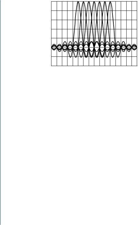
The principle of orthogonal frequency division multiple (OFDM) access has existed for several decades. However, it was only in the last decade that it started to be used in commercial systems. Digital Audio and Video Broadcasting (DAB and DVB), wireless local area networks (WLAN), and more recently wireless local loop (WLL) are the most important wireless applications that use OFDM [54]. The main concept of the method is that one data stream, of Q bps for example, is divided into N data streams, each at a rate of Q/N bps where each one is carried by a different frequency. In OFDM, the subcarrier pulse used for transmission is chosen to be rectangular. This has the advantage that the task of pulse forming and modulation can be performed by a simple Inverse Discrete Fourier Transform (IDFT). Thus, the N data streams are combined together using the Inverse Fast Fourier Transform (IFFT), which can be implemented very efficiently, to obtain a time-domain waveform for transmission as an IFFT. Therefore, in the receiver, a forward FFT is needed to reverse this operation. According to the theorems of the Fourier Transform the rectangular pulse shape will lead to a sin(x)/x spectrum of the subcarriers as shown in Fig. 2.11.
The parallel, and slower data streams, are allowed to overlap in frequency. In this way, the bandwidth of the modulated symbol effectively decreases by N, and its duration increases by N, as well. Therefore, with the appropriate choice of N, frequency-selectivity and ISI (Inter
20 INTRODUCTION TO SMART ANTENNAS
|
1.0 |
|
0.8 |
Amplitude |
0.6 |
0.4 |
|
|
|
Normalized |
0.2 |
0.0 |
|
|
|
|
-0.2 |
|
-0.4 |
|
-8 -7 -6 -5 -4 -3 -2 -1 0 1 2 3 4 5 6 7 8 |
Normalized Frequency (f T)
T)
FIGURE 2.11: OFDM and the orthogonality principle.
Symbol Interference) can be removed. The carrier frequency spacing f is selected so that each subcarrier is orthogonal to all other subcarriers, thus f = 1/ T, where T is the OFDM symbol duration (or, more precisely, the effective duration of the Fourier transform).
OFDM is particularly suited for transmission over a dispersive (i.e., frequency selective) channel. In 1993 Linnertz et al. proposed the multi-carrier code division multiple access (MCCDMA) [55]. It is a new CDMA system based on a combination of CDMA and orthogonal frequency division OFDM where the spreading is performed in the frequency domain, rather than in the time domain as in a DS-CDMA system. In MC-CDMA, each of the M carriers in a multi-carrier system is multiplied by a spreading sequence unique to each user. This system has gained much attention, because the signal can be easily transmitted and received using the Fast Fourier Transform (FFT) device without increasing the transmitter and receiver complexities and is potentially robust to channel frequency selectivity with a good frequency use efficiency [56].

21
C H A P T E R 3
Antenna Arrays and Diversity
Techniques
An antenna in a telecommunications system is the device through which, in the transmission mode, radio frequency (RF) energy is coupled from the transmitter to the free space, and from free space to the receiver in the receiving mode [57–59].
3.1ANTENNA ARRAYS
In many applications, it is necessary to design antennas with very directive characteristics (very high gains) to meet demands for long distance communication. In general, this can only be accomplished by increasing the electrical size of the antenna. Another effective way is to form an assembly of radiating elements in a geometrical and electrical configuration, without necessarily increasing the size of the individual elements [9]. Such a multielement radiation device is defined as an antenna array [59].
The total electromagnetic field of an array is determined by vector addition of the fields radiated by the individual elements, combined properly in both amplitude and phase[58, 59]. Antenna arrays can be one-, two-, and three-dimensional. By using basic array geometries, the analysis and synthesis of their radiation characteristics can be simplified. In an array of identical elements, there are at least five individual controls (degrees of freedom) that can be used to shape the overall pattern of the antenna. These are the [59]:
i.geometrical configuration of the overall array (linear, circular, rectangular, spherical, etc.)
ii.relative displacement between the elements
iii.amplitude excitation of the individual elements
iv.phase excitation of the individual elements
v.relative pattern of the individual elements

22 INTRODUCTION TO SMART ANTENNAS
3.2ANTENNA CLASSIFICATION
In general, antennas of individual elements may be classified as isotropic, omnidirectional and directional according to their radiation characteristics. Antenna arrays may be referred to as phased arrays and adaptive arrays according to their functionality and operation [59].
3.2.1Isotropic Radiators
An isotropic radiator is one which radiates its energy equally in all directions. Even though such elements are not physically realizable, they are often used as references to compare to them the radiation characteristics of actual antennas.
3.2.2Omnidirectional Antennas
Omnidirectional antennas are radiators having essentially an isotropic pattern in a given plane (the azimuth plane in Fig. 3.1) and directional in an orthogonal plane (the elevation plane in Fig. 3.1). Omnidirectional antennas are adequate for simple RF environments where no specific knowledge of the users directions is either available or needed. However, this unfocused approach scatters signals, reaching desired users with only a small percentage of the overall energy sent out into the environment [4]. Thus, there is a waste of resources using omnidirectional antennas since the vast majority of transmitted signal power radiates in directions other than the desired user. Given this limitation, omnidirectional strategies attempt to overcome environmental challenges by simply increasing the broadcasting power. Also, in a setting of numerous users (and interferers), this makes a bad situation worse in that the signals that miss the intended user become interference for those in the same or adjoining cells. Moreover, the single-element approach cannot selectively reject signals interfering with those of served users. Therefore, it has no spatial multipath mitigation or equalization capabilities. Omnidirectional strategies directly and adversely impact spectral efficiency, limiting frequency reuse. These
FIGURE 3.1: Omnidirectional antennas and coverage patterns [4].