

The sextant and its use
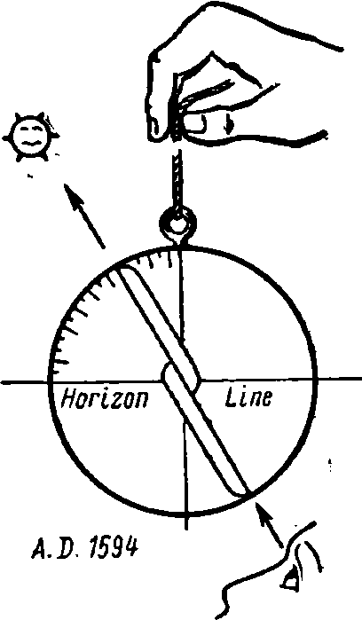
The sextant is an instrument which measures the angle between two objects. The most important function of the sextant is the measurement of altitudes above the sea horizon (Fig. 37). Because of its small dimensions and its accuracy, and because it does not require a stable mounting, it is peculiarly suited for use at sea. The sextant shares with the compass and the chronometer the honour of being one of the three instruments that have made modern ocean navigation possible.
This chapter discusses principally the horizon sextant used by surface navigators. Quintants and octants are similar to sextants in principle and use and do not require discussion. The sextant is so named because its arc approximates one-sixth of a circle although, on account of the principle of double reflection, the instrument measures angles of about 120°. The descriptions in the ensuing sections should, if possible, be read with a sextant in one's hand; they will then be more easily understood and not readily forgotten.
Elements of a sextant. Va- rious makes of sextants differ in details of design and in auxiliary equipment: all in- clude the same principal elements. The drawing (Fig. 38) shows a modern sex- Fig. 37
tant as when a 45° sextant altitude of the sun's lower limb be observed.
On the frame is fixed the graduated arc, or limb, at whose exact centre is pivoted the index arm. The index mirror, fixed on the upper end of the arm, moves when the arm is moved; it reflects the sun to the horizon glass, which is fixed to the frame and does not move.
The half of the horizon glass next to the frame is a mirror which reflects the sun toward the eye; the outer, or left-hand half, is clear glass through which the horizon is seen. A telescope is attached to the frame and directs the line of sight, magnifies the observed body, and clarifies the horizon. Various shades are provided, principally for use when observing the sun.
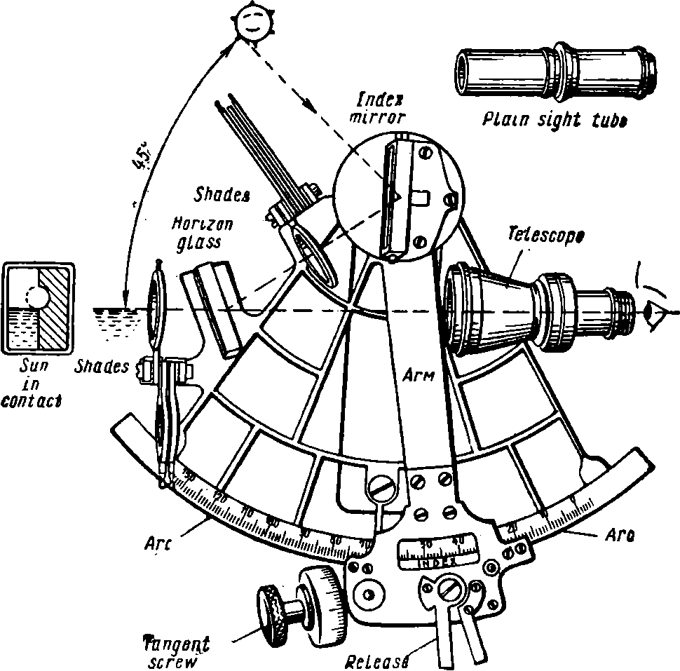
Fig. 38. Elements of a modern sextant
The visible horizon will appear through the clear half of the horizon glass. By moving the arm, the sun, reflected from the index mirror, is brought on the horizon glass and thence reflected back through the telescope to the eye; contact is attained by minutely moving the arm with the tangent screw. The ideal picture in the horizon glass at the instant of contact with the sun's lower limb is shown by the sketch at the left of the sextant.
The arc in the figure reads to degrees and the reading of the sextant is the reading of the arc exactly opposite the index which is usually marked by an arrow on the arm. An altitude may be observed
fo 0'.5 or closer, but if such divisions could be cut on the arc they could not be read. The older device for reading the arc is the vernier which will be discussed first. Thereafter the micrometer shown in the drawing will be easily understood.
Vernier sextants utilize the device of Pierre Vernier (1631) for measuring a fractional part of the equal division of a fixed scale. Fig. 39 shows the position of the vernier on the index arm, and the clamp and the tangent screw with which contact is perfected. When observing, the clamp is loosened and the arm is moved until the body is seen in the horizon glass. The clamp is then made fast and the arm is minutely adjusted by turning the tangent screw until contact is made. The vernier scale is built into the arm and the reading of the arc opposite the arrow which marks the 0 of the vernier is the sextant altitude. A magnifying glass is provided for reading the angles on the arc on the vernier.
Reading a sextant equipped with a vernier is illustrated by Fig. 40. In this case, the scale on the arc shows 20' divisions. The vernier
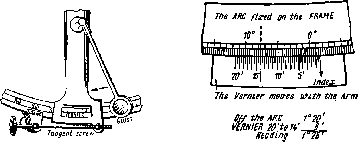
Fig. 39. Arm assembly with vernier Fig. 40. Reading and vernier
scale as shown is marked from 0' to 20' by 0'.5 divisions and serves to read fractional parts of the divisions on the arc to an accuracy of 0'.5. The reading of the sextant is the sum of a reading from the scale on the arc and another reading from the scale of the vernier. First, the reading of the division on the arc next to the right of the zero mark on the vernier is noted as 43°40'. The eye then moves to the left until some division of the scale on the arc appears exactly opposite one of the divisions of the vernier scale. The reading of this division on the vernier scale, marked on the drawing with a dotted line is noted as 7'.5. The sextant reading is the total of 43°40' and 7'.5 or 43°47'.5, the fractional interval of 7'.5 having been read by the aid of the vernier.
The above example illustrates the general method of reading any scale with a vernier, but the divisions on the arcs and on the verniers of sextants often differ from those shown in the drawing. For this reason the beginner should secure expert advice on reading any vernier sextant he proposes to use.
Micrometer sextants are so named because of the device used to read the fractional parts of the divisions of the arc. Fig. 41 shows the assembly on the arm of the tangent screw with its micrometer head and release latch. The arc is graduated only into a scale of degrees. Gear teeth, not visible in the drawings, are cut in the outer or lower edge of the arc, one tooth exactly corresponding to one de-
On the ARC 43° MICROMETER 47'5
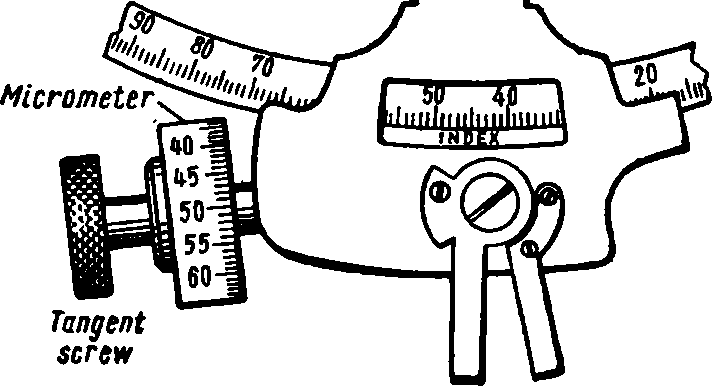
Fig. 41. Micrometer
gree of the scale. These teeth engage a hidden thread on the end of the tangent screw, so that one revolution of the tangent screw moves the index mark exactly 1° on the scale of the arc. Fractional revolutions of the tangent screw measure the fractions of a degree by a division of the micrometer head which reads to 0'.5. The reading of the sextant is the sum of the whole degree reading of the arc next to the right of the index mark, which in the figure reads 43°, and the reading of the micrometer head which is 47'.5, or a total of 43°47'.5.
Choice. The micrometer type is preferable because it is easy to read even when moist and because it eliminates the chance of blunders with a vernier. New sextants issued in the U.S. Navy are of this type, have an arc with a radius of about 7 inches, and weight slightly over 4 pounds. Smaller, lighter instruments are more difficult to hold steady.
Although a nuisance to a beginner, verniers do the work. Practically all instruments of this type read to 10", a degree of accuracy seldom obtained in actual practice.
Not less than two sextants should be on every ship at sea. There is always a chance that by some accident one will be ruined or lost.
Care. Once you have a good sextant, properly adjusted, remember that it is a delicate instrument and must not be knocked around. It should be kept in its box, accessible to the deck, with the box arranged so that it cannot jump out of position and slide about in a seaway. The instrument should be removable without moving the box and should be returned thereto immediately after taking sights. It must not be dropped and should not be long in the direct rays of the sun. When shelter is not available, a towel will protect it while waiting to get a sight. Moisture must not remain on the mirrors and glass surfaces, which are best dried with old, clean, soft linen. Silk or chamois may scratch the mirrors; cotton cloth or waste leaves lint. A 50 per cent alcohol solution helps clean glass and is safe to use on a sextant. Never polish the arc or the vernier; when necessary clean with ammonia. A few drops of oil are needed occasionally on the sextant's working parts.
Adjustments of the sextant are fully described in. Bow-ditch (1938). The amateur should remember Raper's advice, "The adjusting screws are never to be touched except from necessity, and then with the greatest possible caution." Better leave all adjustments to your instrument dealer rather than risk upsetting the sextant on which your landfall depends.
Tfie
Vernier mom mth the Arm
On
the ARC *3°40 On the VERHtER 7'.
5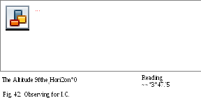
Fig. 43. Reading off the arc
Index correction (/. C). Let the sextant be held vertically with the telescope pointed at the horizon and with the index mark on the arm about opposite the 0° division of the arc. With the tangent screw bring the direct and reflected horizon lines exactly in line as in Fig. 42. Evidently an altitude of 0° is being measured. Examine the reading of the instrument which will probably be slightly different from zero. This difference is the index error in the instrument, known as the index correction. A somewhat more accurate method of determinating the index correction is to bring the direct and reflected images of a star into coincidence.
The index correction must always be applied to any altitude as read from the sextant; thus, adding or subtracting the /. C. is an element of correcting every altitude. This is the practice of sea navigators, because any attempt to reduce the index error to zero may upset other adjustments which the theory of the sextant requires to be exact. The index error is not necessarily constant and should be verified from time to time.
If the index, or zero of the vernier, lies to the left of the 0° mark, or on the arc, the /. C. is marked (—) and must be subtracted from all readings; if the index appears to the right of 0°, or off the arc, the /. C. is (+) and must be added to the reading. The old rule is: "When it's on it's off and when it's off it's on."
Reading the /. C. is no different from reading any other angle except when the zero of the vernier is off the arc to the right of the 0° mark. In this case the left-hand division of the vernier must be considered as its zero and its divisions must be counted from that point to the right. See Fig. 43, which also suggests that the same result is obtained by subtracting the usual vernier reading from its highest reading. To illustrate the principle, the figure reads 1°26' off the arc, which far exceeds any ordinary index correction.
Observing the sun. It is customary to observe the angle between the horizon and the lower edge of the sun's disk which navigators call the sun's lower limb. The beginner may well take his first sights without any telescope or sight tube because he can see what he is doing. Thereafter he should use the plain sight tube, or the lowpower telescope.
Select the desired telescope or sight tube and screw it in place. See that all glass surfaces are clean and that all shades are thrown back. Go on deck and choose a comfortable steady position from which the sun and the horizon under it can be seen. Focus the telescope on the horizon and, if necessary, turn a shade before the horizon glass to limit the glare of the sun's reflection from the water. Turn one or more shades before the index glass according to the estimated brightness of the sun.
Hold the instrument vertically in the right hand, both eyes open, and direct the line of sight to the horizon directly under the sun. While continuing to hold the horizon on the direct line of vision, move the index arm out from 0°, away from the observer, until the reflected image of the sun is seen in the horizon glass, with its lower edge preferably near the horizon, as in (1) Fig. 44. Pushing the arm out lowers the sun as it appears on the glass. If the student finds difficulty in getting the reflected sun on the horizon glass, first find its approximate altitude as in Fig. 44. When the sun is approximately on the horizon, vernier sextants of the older type require that the arm be clamped. With the tangent screw, perfect the contact of the sun's lower limb with the horizon as in (2). The beginner may forget which
way
to turn the tangent screw to move the sun up or down on the
horizon glass. On most sextants, if the right-hand edge of the
tangent screw be moved down, the sun will appear to move down.
Having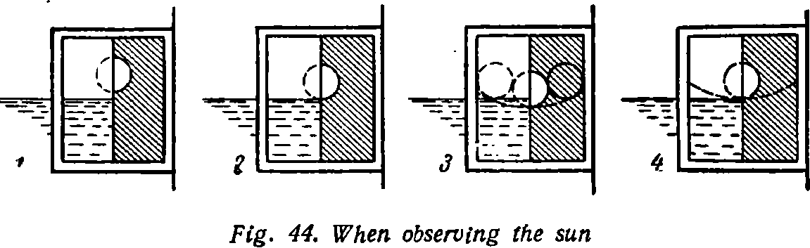
made contact, determine whether the instrument has been held vertically by rotating it slightly about the line of sight. The sun will appear to move in a small arc as in (3). The instrument is vertical when the sun appears lowest, therefore again perfect the contact, as in (4). The instant of contact is the time of the observation. The reading of the instrument is the sextant altitude.
The observation just described may be simple from the bridge of a steamer in fine weather but it is seldom easy to get an accurate altitude from a small sailing craft at sea. Beginners often are more at fault with their altitudes than with figures or theory.
Evaluation of altitudes. An experienced navigator forms a judgement of the probable accuracy of every altitude he observes. From a big ship and under perfect conditions the error, plus or minus, may not exceed 0'.2; a more probable assumption, under favourable circumstances, is 0'.5. It may be much greater on a small craft in foul weather where 5', plus or minus, is nearer the truth.
The observer may check his skill with the sextant under various conditions by taking a series of altitudes of the sun at regular intervals. Have an assistant, with a watch, prepared to record the sextant's readings. Observe a few altitudes; thereafter take the sun's altitude each minute or half-minute, as warned by your assistant, and let him record the sextant readings. The difference between such altitudes, observed at regular intervals, should be constant during any few minutes of time. Otherwise consider the observations as possibly in error by plus or minus the variations in the differences.
It is often desirable to take several altitudes in succession or, if possible, at regular intervals. Comparison of their difference with the difference in time between the sights will give some indication on the most accurate altitudes. Some navigators average the altitudes and times of several sights. Others prefer to choose the sight which is considered most accurate. Sometimes the best three sights are worked separately. The extra arithmetic required by the last suggestion
is a good check for the beginner and further indicates the probable limits of error in the observations.
Notwithstanding the difficulties of getting an accurate, properly timed altitude, a skilled observer, seeing a chance to catch the sun through a hole in the clouds, may pick up his sextant and stop watch and quickly get a single valuable observation.
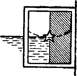
The moon's altitude is often easier to observe than is that of the sun. Probably because of an old prejudice against moon sights the subject is hardly mentioned in most books on navigation. The moon may be observed while the sun shines, or in twilight and sometimes during the night when the light from the moon itself makes the horizon visible. Shade glasses are seldom required, otherwise the sight is taken as when observing the sun. It is often necessary to observe the moon's upper limb because of the varying shape of the visible portion of the moon's disk, in which case the image in the horizon glass may look somewhat as in Fig. 45. When in bright sunlight and the moon is pale, or when the horizon is difficult to see as at night, it is helpful to approximate the altitude as in Fig. 46.


but COMING ~ gradually dOWN
Fig. 46. When observing a star
Altitudes of stars and planets. The most favourable time for observing these bodies is during twilight when the horizon is at its best. However, with a sextant that has a good star telescope and well silvered mirrors, there is little difficulty at any time on a clear night, especially with moonlight, in obtaining reliable star sights. Whenever stars are to be observed one should go on deck several minutes before taking the sights and let the eyes become adjusted to the semi-darkness.
Methods for taking the altitude of a star or planet differ somewhat from those used when observing the sun or the moon. Stars are only points of light and many such twinkling points may be visible. If the line of vision be held on the horizon, as when observing the sun, and if one attempts to bring the desired star to the horizon in the usual way, several other stars may appear in the mirror, among which the observer cannot identify the star he proposes to use. Therefore different methods are used to bring the star down to the horizon.
Select the low-power telescope or the high-power erecting star telescope, if you have one. Do not use the inverting telescope found with some sextants, because it confuses a beginner. Focus the telescope on the horizon and fix it to the sextant; turn back all shades. With the sextant set at zero, and both eyes open, point the line of vision at the star; the direct view will be seen approximately coincident with the star as reflected from the horizon mirror. Slowly lower the line of vision and at the same time move the index arm out and away from the zero on the arc, always keeping the image of the star visible in the horizon mirror. When the reading of the arc approximates the altitude of the star, the horizon will appear and the star is said to have been "brought down." Perfect the contact so that the point of light which is the image of the star is on the horizon line, and test the vertical position of the sextant as when observing the sun. The reading of the instrument is the sextant altitude of the star at the instant of contact. Avoid bright light until star observations are completed and, if possible, have an assistant to take the time.
An unexpected opportunity to observe a single star may give a valuable line of position. It is usual, however, to select two or three
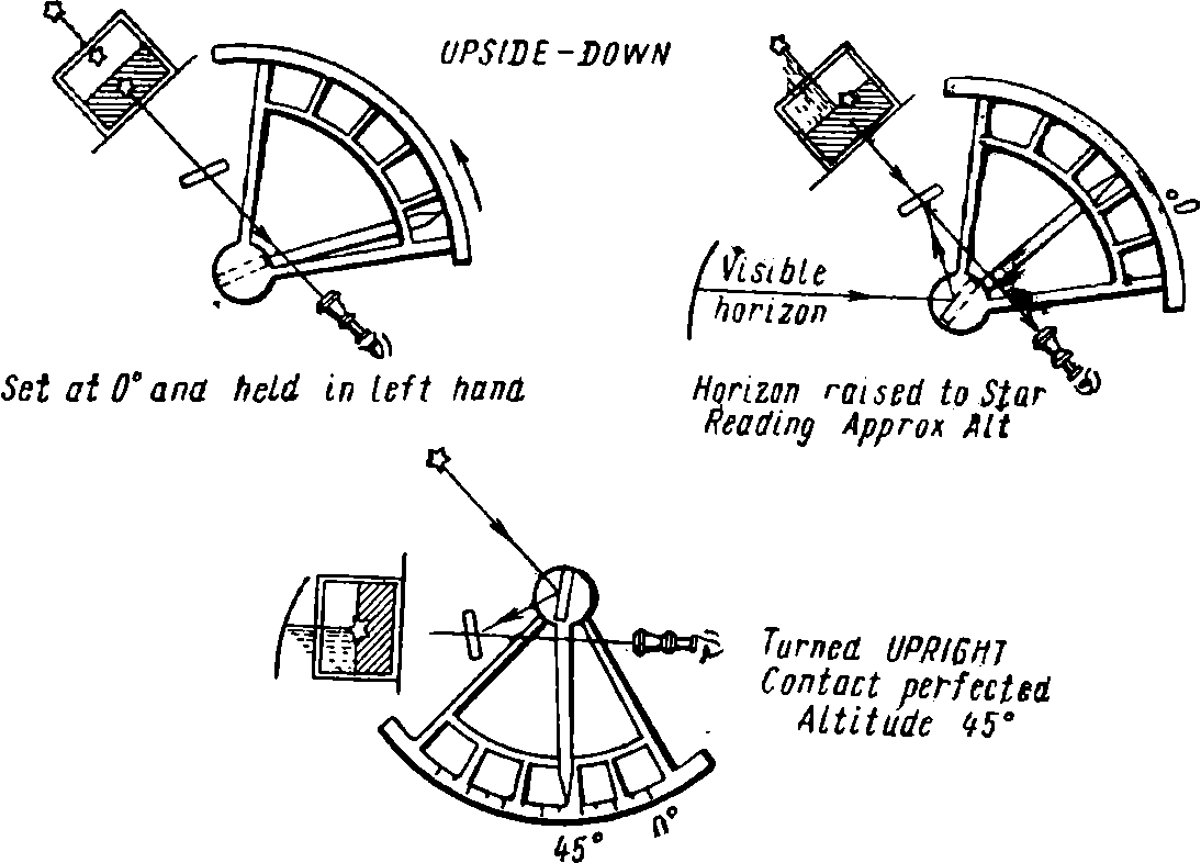
Fig. 47. The sextant upside down
stars to be observed at about the same time for a fix. Preparations for a round of stars, including estimating altitudes for setting the sextant in advance, are discussed at length, in Chapter 31.
Upside down! When observing a star some navigators
prefer the method shown in Fig. 47. With the index arrow at zero, turn the sextant upside down and direct the line of sight through the telescope to the star itself as seen through the clear half of the horizon glass. Hold the instrument in this position and push out the arm until the reflected line of the horizon appears across the horizon glass through which the star is also seen. With the arm thus fixed at the approximate altitude, reverse the sextant and perfect the contact in the usual way.
The advantage of the above method is that the desired star remains constantly in view while the approximate altitude is obtained with the inverted sextant, and immediately appears in the horizon glass when the sextant is righted, without the star's being "brought down." The bright stars are far enough apart to eliminate the chance of picking up the wrong star with the righted sextant. This method may also be used when it is difficult to get a faint, daylight image of the moon, or the sun, onto the horison glass.
ОГЛАВЛЕНИЕ
ЧАСТЬ ПЕРВАЯ
Стр.
Предисловие 3
I. Лоция 5
-
Огни I
-
Буи и береговые знаки \f
-
Опасности
-
Якорные стоянки ~1
-
Наставления
-
Приливы, отливы и приливо-отливные течения
-
Портовые устройства ^
-
Портовые правила "
II. Карты 69
-
Сокращения ^9
-
Заголовки
-
Примечания 7^
-
Предостережения /б
III. Список огней 80
-
Извещения мореплавателям 85
-
Метеосводки 95
VI. Выдержки из „Адмиралтейского списка радиосигналов'* 98
Сокращения ^
VII. Команды . 114
ЧАСТЬ ВТОРАЯ
I. Введение к чтению чартера и коносамента П8
-
Коносамент ^0
-
Извещения о готовности • 129
-
Морской протест 130
V. Грузовой манифест 131
-
Англо-русский словарь
-
Русско-английский словарь 149
ЧАСТЬ ТРЕТЬЯ
Сборник текстов
-
Приборы 157
-
Основы пользования радаром 167
-
Азимуты 198
CONTENTS
PART ONE
Page
Pilot-book 5
-
Lights *
-
Buoys and Beacons gJz
-
Dangers ~{
-
Anchorages ^0
-
Directions Vi
-
Tides and Tidal Streams ™
-
Port Facilities *i
-
Port Regulations 00
II. Charts 69
-
Abbreviations !j?
-
Headings
-
Notes
-
Cautions '°
-
List ol Lights 80
-
Notices to Mariners 85
V. Weather Reports 95
VI. Excerpts from "The Admiralty List of Radio Signals" 98
1 1 о
Abbreviations ll°
VII. Commands 114
PART TWO
-
Charter Parties and Bills of Lading (Introduction) 118
-
Bill of Lading 120
-
Notices of Readiness 129
-
Ship's Protest 130
V. Manifest of Cargo • • • • 131
-
English-Russian Vocabulary 132
-
Russian-English Vocabulary 149
PART T H RE
Reader
-
Instruments 157
-
Fundamentals of the Use of Radar 167
-
Azimuths 198
\Дорошкевич Нина Орестовна\
Мандрик Владимир Петрович Смирнова Мария Семеновна
Английский язык для судоводителей
Редактор А. И. Гладштейн Издательский редактор В. С. Анощенкова Художник В. Д. Грызлов Технический редактор Н. Н. Баранова Корректоры Л. С. Здитовецкая, Е. Б. Комарова
Сдано в набор 4/11-70 г. Подп. к печати 15/VII-71 г. Формат 60X90Vie- Объем 13,5 печ. л. Уч.-изд л. 14,82. Изд. № А-190. Тираж 46.000 экз. Зак. № 2442. Цена 41 коп. План выпуска литературы изд-в.&,«Высшая школа» (вузы и техникумы) на 1971 г. Позиция № 129.
Москва, К-51, Неглинная ул., д. 29/14, Издательство «Высшая школа»
Ордена Трудового Красного Знамени Московская типография № 7 «Искра революции» Главполиграфпрома Комитета по печати при Совете Министров СССР г. Москва, пер. Аксакова, 13