

Magnetic
%rth
Magnetic
North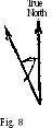

Variation West
Variation East
Direction angle, bearing, course, and heading when referred to the magnetic meridian are called, respectively, magnetic direction angle, magnetic bearing, magnetic course, and magnetic heading.
Variation. At any place on the earth's surface the angle between the true, and the magnetic meridian is the variation at that place.
Variation is measured in degrees from the true meridian. It is called east (+) when magnetic north is to the right of the true north
(See Fig. 7), west (—) when to
Magnetic Magnetic the left (See Fig- 8). The reason

in the former case the reading opposite the lubber's line will be too small and the variation must be added to the magnetic reading to obtain the true reading, while in the latter case the reading is too large and the variation must
be subtracted. Fig. 9 Deviation. Owing to the
magnetism of the iron in a ship, the compass needle is deflected to the right or left of the magnetic meridian. This angular deflection, called deviation, is measured in degrees and named east (+) when the compass needle is to the right of the magnetic meridian, west (—) when to the left (See Fig. 9). In the case of deviation the argument in regard to the convention of signs is similar to that used for variation. Deviation is one of the most illusive factors in navigation because it is constantly subject to change. For example, compass deviation tends to change when the ship's heading is altered, when a cargo containing iron is taken aboard, when the cranes or guns are trained to a new position, when the ship undergoes extensive repairs, when the ship is subjected to a severe concussion, and when the ship changes her latitude.
Direction angle, bearing, course, and heading when referred to the axis of the compass card are called, respectively, compass direction angle, compass bearing, compass course, and compass heading.
Deviation can be determined by swinging ship, that is steadying the ship on various headings, comparing the magnetic and compass bearings of a known object (at least 6 miles distant) on each of these headings, and recording the results. The compass bearings are read from the compass card and the magnetic bearing is determined independently, by algebraically adding the variation at the place to the true bearing or by reading a compass ashore in the vicinity of the ship. Figures 10 to 13 illustrate the process of swinging ship.

Fig. 10 Fig. 11
In Fig. 10 the ship is shown on magnetic heading 0°. A distant object is observed on magnetic bearing 50° while the compass bearing is 40°. Hence in this case:
Deviation=50°—40°= + 10° (east).
In Fig. 11 the ship is shown on magnetic heading 90°. The distant object is still on magnetic bearing 50° but the compass bearing has changed to 55°. Hence in this case:
Deviation=50°—55°=— 5° (west).
In Fig. 12 the ship is shown on magnetic heading 180°. The distant object is still on magnetic bearing 50° but the compass bearing has changed to 45°. Hence in this case:
Deviation=50°—45°=+5° (east).
In Fig. 13 the ship is shown on magnetic heading 270°. The distant object is still on magnetic bearing 50°, but the compass bearing has changed to 60°. Hence in this case:
Deviation=50°—60°=—10° (west).
It should be noted that in all four cases the magnetic bearing of the object remained the same while the compass bearing changed, thus enabling the navigator to measure the deviation at different headings of the ship.
 Relations
between
compass
errors
and
course.
In
Fig.
14
ON
represents
true north, 05
the
direction of
Relations
between
compass
errors
and
course.
In
Fig.
14
ON
represents
true north, 05
the
direction of
t he
ship's track, ОС
the
direction of the compass needle, and OM
the
direction of the magnetic meridian. Then the variation is
represented by angle V,
the
deviation by D, the true course by Си
the
magnetic course by Cm. and the compass course by Cc.
From
Fig.
14
we
have:
he
ship's track, ОС
the
direction of the compass needle, and OM
the
direction of the magnetic meridian. Then the variation is
represented by angle V,
the
deviation by D, the true course by Си
the
magnetic course by Cm. and the compass course by Cc.
From
Fig.
14
we
have:
Ct=Ce+V+D, (1) Cm=Cc+D. (2)
V is positive if the variation is east, FiS- 14 negative if west. The same is true of
deviation.
If the right member of (1) or (2) is greater than 360°, 360° should be subtracted; if the right member is negative, the corresponding course is obtained by subtracting its numerical value from 360°.
For example, if the compass course of a ship is 350°, if variation V is 45° east and deviation D is 20° west, we have from (1) and (2): true course C/=350°+45°—20°—360°= 15° magnetic course Cm=350°—20°=330°.
Also if the true course of a ship is 20°, if the variation is 10° east and the deviation is 20° west, we have from equations (1) and (2):
20°=CC+10°—20°, or Cc=30°, Cm=30°—20°=10°.
Observe that the pilot reads the compass course Cc opposite the lubber's line, obtains the variation from his chart, the deviation from data determined for the ship, and substitutes the quantities in (1) and (2) to obtain Q and Cm. Of course, if Ct is known, Cm, V, and D may be substituted in (1) and (2) and the result solved for Cc
The process of finding true course (illustrated in the first example) is called correcting. The reverse process (illustrated in the second example) is called uncorrecting.
The method explained below is used by a considerable number of navigators. Although not recommended, it may be used.
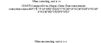
In the mnemonic
Can Dead Men Vote Twice*
the initial letters C, D, M, V, T suggest, respectively, Compass reading, Deviation, Magnetic reading, Variation, and True reading. When using the mnemonic write in order the initial letters of Can Dead Men Vote Twice, under the appropriate letter write each known quantity, over the letters draw an arrow pointing toward the right (as shown at the top of the accompanying table), on this arrow write when correcting east is + and, using this convention for signs, find each unknown by adding algebraically the two quantities written immediately to one side of it. When uncorrecting use the convention indicated at the bottom of the table.
*
Могут ли мертвые голосовать дважды
(Прим.
ред.).
 Chronometer.
A chronometer is an extremely accurate, expensive timepiece
supported on gimbals in a wooden box. To ensure its accuracy
aboard ship, great care is exercised, in protecting it from shocks,
changes of temperature, dampness, and magnetic influences.
Chronometer.
A chronometer is an extremely accurate, expensive timepiece
supported on gimbals in a wooden box. To ensure its accuracy
aboard ship, great care is exercised, in protecting it from shocks,
changes of temperature, dampness, and magnetic influences.
Sextant. A sextant is a small portable instrument used for measuring angles subtended by distant objects and for measuring the altitudes (angular distances above the horizon) of celestial bodies.
Atfached to the frame is a limb or arc (of a circle) provided with a scale graduated in degrees. Each interval representing a degree is subdivided into smaller intervals representing usually 10', 15', or 20'.
At the centre of the arc's circle is pivoted at index arm whose lower end is provided with a vernier to allow more accurate readings. The zero mark on the vernier is the index at which readings are made. An index mirror is attached to the upper end of the index arm with its plane perpendicular to that of the arm.
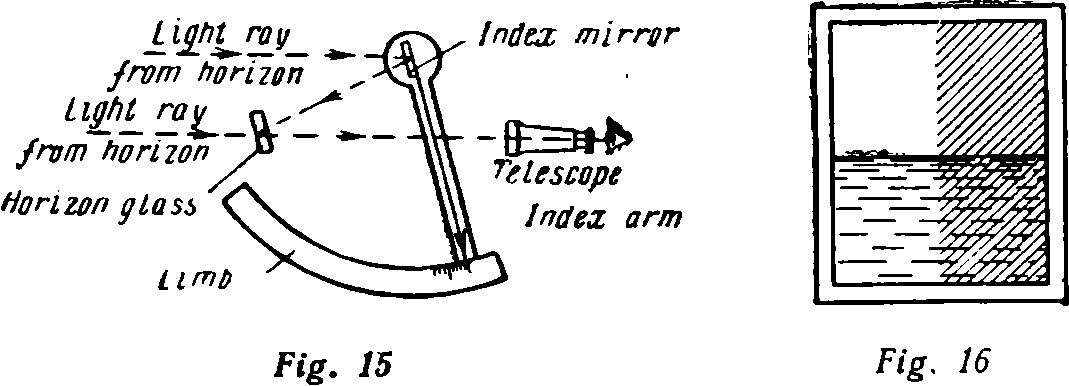
A horizon glass is attached to the frame with its plane perpendicular to that of the frame. The half of this glass nearest the frame is a mirror, the other half is clear glass.
A telescope is attached to the frame.
To understand how these essential parts of a sextant are arranged, suppose the index arm is rotated until the index glass is parallel to the horizon glass. In this position the zero mark of the vernier should be in line with the zero mark of the limb. With the index arm in this position, suppose the sextant to be held vertically with the telescope directed at the horizon. The horizon is far enough from the observer so that the rays of light from it to the horizon glass and to the index glass are practically parallel. The observer, looking through the clear half of the horizon glass, will see the horizon, and looking into the mirrored half of the horizon glass will see the horizon reflected from the index glass.

Fig. 18 Fig. 19
Taffrail log. A taffrail log or patent log (See Fig. 19) is used on small vessels to measure the distance a ship travels through the water. This instrument consists of a small propeller, a long non-twisting cable, and a recording device. The propeller is towed at the end of the cable, which is attached to the recording device as indicated in Fig. 19. As the propeller is dragged through the water, it revolves, and this rotary motion is transmitted through the cable to the recording device, which is so calibrated as to register the distance run in miles and tenths of miles. In order that the cable will clear the ship, the recording device is located, as the name indicates, on the taffrail or stern rail of the vessel.
Pitometer. The pitometer is a pressure-type log used on larger vessels. An intake tube CC'C" and an outflow tube BB'B" project through the bottom of the ship at H. The ends B" and C" of the tubes are connected to a mercury differential consisting of a float chamber, which communicates with the mercury tubes EE' shown in the figure.
Revolution tables and curves. A table of revolutions is made out for each ship from actual trials. It gives the revolutions per minute of the propeller shaft required for each knot of the ship's speed in smooth water, when the draft is normal and the bottom clean. This table is a good guide for estimating the speed through the water if due allowances are made for variations in draft, the state of the ship's bottom, and the effect of wind and sea. A revolution curve is also used. It is plotted by using as ordinates the ship's propeller speed in revolutions per minute and as abscissas the ship's speed in miles per hour.
The dead recording tracer. This instrument traces automatically the course steered and distance steamed. The device is connected with both the gyro compass and the pitometer. In general it can be set at the various scales used on navigator's charts and hence can be used to trace the track of the ship directly on the chart.
Sounding instruments. Soundings (measurements of water depth) are an aid to a navigator in determining position especially in fog. For this purpose a hand lead (consisting of a suitably marked line with a piece of lead of 7 to 14 lb. attached) is used in shallow water.
Soundings in deep water may be obtained accurately by means of a sounding machine. Although these machines are of various types, they all depend upon the principle that the depth of water varies.
A sonic depth finder or fathometer is used on many ocean-going vessels for obtaining soundings. This instrument measures the time interval between the instant a sound is generated and the return of the echo. This result is mechanically converted into fathoms read on a dial.
The range finder. A range finder, the most important of all gunnery instruments, is designed to obtain the distance of an object from the instrument. The observer at the instrument looks through the eyepiece at the target and sees it in two pieces. He then turns a small knob, gradually bringing the two images into alignment. When the two images fit exactly, he looks at a scale beside the eyepiece and reads the exact range.