

Chapter 2 NI ELVIS II Hardware
NI ELVIS II Benchtop Workstation
Caution Refer to the Read Me First: Safety and Radio-Frequency Interference document before removing equipment covers, or connecting or disconnecting any signal wires.
This section describes the NI ELVIS II Benchtop Workstation.
The workstation control panel provides easy-to-operate knobs for the variable power supplies and function generator, and offers convenient connectivity and functionality in the form of BNC and banana-style connectors to the function generator, scope, and DMM instruments.
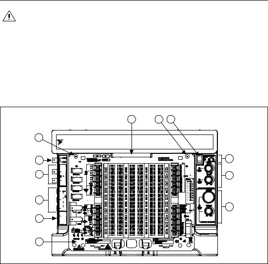
Figure 2-2 shows the control panel parts locator diagram.
6
5
4
3
2
|
7 |
6 |
8 |
|
NATIONAL |
|
NI ELVIS II |
INSTRUMENTS |
|
||
|
|
||
10V MAX |
|
9 |
|
|
5V TTL |
|
|
SCOPE |
|
|
|
10VDC |
|
|
|
7Vrms MAX |
|
|
|
CH 0 |
|
10 |
|
1M |
25pF |
|
|
CH 1 |
|
|
|
DMM |
|
|
|
V |
|
|
|
60VDC |
|
|
|
20Vrms |
|
|
|
MAX |
|
|
|
COM |
|
|
|
2A MAX |
|
11 |
|
A |
|
||
FUSE |
|
|
|
F 3.15A H 250V |
|
|
|
Sand Filled |
|
|
|
5-20 mm |
|
|
|
1
1 |
NI ELVIS II Series Prototyping Board |
6 |
Prototyping Board Mounting Screw Holes |
2 |
DMM Fuse |
7 |
Prototyping Board Connector |
3 |
DMM Connectors |
8 |
Prototyping Board Power Switch |
4 |
Oscilloscope Connectors |
9 |
Status LEDs |
5 |
Function Generator Output/Digital Trigger Input |
10 |
Variable Power Supplies Manual Controls |
|
Connector |
11 |
Function Generator Manual Controls |
|
|
|
|
Figure 2-2. Top View of NI ELVIS II Benchtop Workstation with Prototyping Board
NI ELVIS II User Manual |
2-2 |
ni.com |

Chapter 2 NI ELVIS II Hardware
The benchtop workstation has the following controls and indicators:
•USB LEDs
–Ready—Indicates that the NI ELVIS II hardware is properly configured and ready to communicate with the host computer.
–Active— Indicates activity on the USB connection to the host computer.
Table 2-1. Benchtop Workstation USB LED Patterns
ACTIVE LED |
|
READY LED |
Description |
|
|
|
|
|
|
|
|
Off |
|
Main power is off. |
|
|
|
|
|
Yellow |
|
Off |
No connection to the host computer is detected. Make |
|
|
|
sure NI-DAQmx driver software is loaded and the |
|
|
|
USB cable is connected. |
|
|
|
|
Off |
|
Green |
Connected to a full speed USB host. |
|
|
|
|
Off |
|
Yellow |
Connected to a high speed USB host. |
|
|
|
|
Green |
|
Green or Yellow |
Communicating with host. |
|
|
|
|
•Prototyping Board Power Switch and LED—Controls the power to the prototyping board.
Caution Ensure that the prototyping board power switch is off before inserting or removing it from the benchtop workstation.
•Variable Power Supplies Controls
–Positive Voltage Adjust Knob—Controls the output voltage of the positive variable power supply. The positive supply can output between 0 and +12 V.
–Negative Voltage Adjust Knob—Controls the output voltage of the negative variable power supply. The negative supply can output between 0 and –12 V.
Note These knobs are only active when the associated variable power supply is set to Manual Mode. An LED next to each knob lights when the variable power supply is in Manual Mode.
© National Instruments Corporation |
2-3 |
NI ELVIS II User Manual |

Chapter 2 NI ELVIS II Hardware
•Function Generator Controls
–Frequency Knob—Adjusts the output frequency of the generated waveform.
–Amplitude Knob—Adjusts the amplitude of the generated waveform.
Note These knobs are only active when the Function Generator is set to Manual Mode. An LED next to each knob lights when the Function Generator is in Manual Mode.
•DMM Connectors
–Voltage, Resistance, and Diode Banana Jack (red)—The positive input for voltage based DMM functionality.
–Common Banana Jack (black)—The common reference connection for DMM voltage, current, resistance, and diode measurements.
–Current Banana Jack (red)—The positive input for DMM current measurements.
–Fuse Cartridge—Replaceable fuse to protect the current signal path. Refer to the NI ELVIS II Specifications at ni.com/manuals for fuse information
Note The NI ELVIS II DMM connections for voltage, current, resistance, and diode measurements are available only through the banana jacks. They are not routed to the prototyping board.
•Oscilloscope (Scope) Connectors
–CH 0 BNC Connector—The input for channel 0 of the oscilloscope.
–CH 1 BNC Connector—The input for channel 1 of the oscilloscope.
Note The NI ELVIS II Oscilloscope channels 0 and 1 are available only through the BNC connectors. They are not routed to the prototyping board.
•FGEN/Trigger Connector—Optional output of the function generator or a digital trigger input.
NI ELVIS II User Manual |
2-4 |
ni.com |