

5
Quality places
Llewelyn Davies Yeang

1ODPM (2005) Planning Policy Statement 1: Delivering Sustainable Developments. London: TSO.
2Welsh Assembly Government (2002)
Planning Policy Wales. Cardiff: NAfW.
3Welsh Assembly Government (2002)
Technical Advice Note 12:
Design. Cardiff: NAfW.
4Communities and Local Government (2006)
Planning Policy Statement
3:Housing. London: TSO. 5 Welsh Assembly
Government (2002)
Ministerial Interim Planning Policy Statement 01/2006: Housing. Cardiff: NAfW.
6 CABE (2002) The Value of Good Design. London CABE; CABE (2006) Buildings and Spaces: Why Design Matters. London: CABE; CABE (2006) The Value Handbook. London: CABE; and CABE (2006)
The Cost of Bad Design. London: CABE.
Chapter aims
•Promote the place function of streets and explain the role that streets can play in making better places.
•Stress the importance and value of urban design as a framework within which streets are set out and detailed.
•Set out expectations for the design of quality places, as well as routes for safe and convenient movement.
•Discuss local distinctiveness.
5.1Introduction
5.1.1 The previous chapter described how to plan sustainable communities, covering issues such as the need to plan for connected layouts, mixed uses and walkable neighbourhoods.This chapter develops those themes by demonstrating the importance of quality and encouraging the use of three-dimensional urban design.
5.2The value of good design
5.2.1Good design plays a vital role in securing places that are socially, economically and environmentally sustainable (see ‘Gateshead case study box’). Planning Policy Statement 1: Delivering Sustainable Development (PPS1)1 emphasises this. It states that ‘good design ensures attractive, usable, durable and adaptable places and is a key element in achieving sustainable development. Good design is indivisible from good planning … and should contribute positively to making places better for people’ (Wales: refer to Planning Policy Wales,2 Section 2.9, and Technical Advice Note (TAN) 123).
5.2.2This message is also reinforced by
Planning Policy Statement 3: Housing (PPS3)4 which states that ‘good design is fundamental to the development of high-quality new housing, which contributes to the creation of sustainable, mixed communities’. (Wales: refer to Ministerial Interim Planning Policy Statement 01/2006: Housing5).
5.2.3There is growing evidence of the benefits of a public space, development or building that improves people’s sense of well being, although these benefits can often be difficult to quantify.
Case study
Staiths South Bank, Gateshead
Peter O’Brien, Llewelyn Davies Yeang
Figure 5.1 New development at Staiths South Bank, Gateshead.
•A significant level of detailed effort was required to negotiate deviation from standards – this was resource intensive. MfS guidance aims to avoid this by promoting the acceptance of innovation (Fig. 5.1).
•The homes are relatively affordable which shows that high-quality design need not be expensive.
•Parking was limited to a ratio of one space per house, which provided scope for a higher-quality public realm.
•The scheme was designed as a Home Zone.
However, evidence is also growing of the economic, social and environmental benefits of good urban design. Good design should not be considered as an optional or additional expense – design costs are only a small percentage of construction costs, but it is through the design process that the largest impact can be made on the quality, efficiency and overall sustainability of buildings, and on the long-term costs of maintenance and management (Fig. 5.2).
5.2.4 CABE has collated a supporting evidence base,6 which includes the following:
•compact neighbourhoods that integrate parking and transport infrastructure, encourage walking and cycling, and so reduce fuel consumption;
•properties adjacent to a good-quality park have a 5–7% price premium compared with identical properties in the same area but that are away from the park; and
•the benefits of better-designed commercial developments include higher rent levels, lower maintenance costs, enhanced regeneration and increased public support for the development.
Manual for Streets |
51 |

7DETR and CABE (2000) By Design: Urban Design in the Planning System: Towards Better Practice. London: Thomas Telford Ltd.
8Llewelyn Davies (2000)
The Urban Design Compendium. London: English Partnerships and The Housing Corporation.
9 DTLR and CABE (2001)
Better Places to Live: By Design. A Companion Guide to PPG3. London: Thomas Telford Ltd.
10www.buildingforlife.org.uk.
11Welsh Development Agency (WDA) (2005)
Creating Sustainable Places. Cardiff: WDA.
12LDA Design (2005) A Model Design Guide for Wales: Residential Development. Cardiff: Planning Officers Society Wales.
13CABE (2005) Housing Audit: Assessing the Design Quality of New Homes in the North East, North West and Yorkshire & Humber. London: Ernest Bond Printing Ltd.
Una McGaughrin, Llewelyn Davies Yeang
Figure 5.2 Newhall, Harlow – a masterplan-led approach with bespoke housing design.
5.3Key aspects of urban design
‘Urban design is the art of making places for people. It includes the way places work and matters such as community safety, as well as how they look. It concerns the connections between people and places, movement and urban form, nature and the built fabric, and the processes for ensuring successful villages, towns and cities.’
By Design: Urban Design in the Planning
System: Towards Better Practice7
5.3.1It is important to appreciate what this means in practice. It is easy to advocate places of beauty and distinct identity, but it takes skill to realise them and ensure they are fit for purpose. A number of key documents and initiatives provide an introduction, including the Urban Design Compendium,8 Better Places to Live: By Design9 and Building for Life10 (see box) (Wales: see also Creating Sustainable Places11 and A Model Design Guide for Wales12).
5.3.2These basic aspects of urban design, however, are not being realised in many new developments. All too often, new development lacks identity and a sense of place. In these cases, it lets communities and users down, and undermines the aims of the sustainable communities agenda.
5.3.3Frequently, it is in the interaction between the design and layout of homes and
streets that attempts to create quality places break down.13 In the past, urban designers sometimes felt that their schemes were compromised by the application of geometrical standards to highways that were current at the time. Highway engineers, in turn, have occasionally raised concerns about layouts that did not comply with the design criteria to which they were working.
5.3.4 MfS advocates better co-operation between disciplines, and an approach to design based on multiple objectives.
5.4Street dimensions
5.4.1 Most neighbourhoods include a range of street character types, each with differing characteristics, including type of use, width and building heights. These characteristics dictate how pedestrians and traffic use the street.
Width
5.4.2 Width between buildings is a key dimension and needs to be considered in relation to function and aesthetics. Figure 5.3 shows typical widths for different types of street.
The distance between frontages in residential streets typically ranges from 12 m to 18 m, although there are examples of widths less than this working well. There are no fixed rules but account should be taken of the variety of activities taking place in the street and of the scale of the buildings on either side.
52 |
Manual for Streets |

The principles of urban design
The fundamental principles of urban design are described more fully in By Design: Urban Design in the Planning System:Towards Better Practice.14
They involve expressing the main objectives of urban design through the various aspects of the built form.
The objectives of urban design can be summarised as follows:
•Character – a place with its own identity.
•Continuity and enclosure – a place where public and private spaces are clearly distinguished.
•Quality of the public realm – a place with attractive and successful outdoor areas.
•Ease of movement – a place that is easy to get to and move through.
•Legibility – a place that has a clear image and is easy to understand.
•Adaptability – a place that can change easily.
•Diversity – a place with variety and choice.
The aspects of the built form are described as follows:
•Layout: urban structure – the framework of routes and spaces that connect locally
and more widely, and the way developments, routes and open spaces relate to one another.
•Layout: urban grain – the pattern of the arrangement of street blocks,
plots and their buildings in a settlement.
•Landscape – the character and appearance of land, including its shape, form, ecology, natural features, colours and elements, and the way these components combine.
•Density and mix – the amount of development on a given piece of land and the range of uses. Density influences the intensity of development, and, in combination with the mix of uses,
can affect a place’s vitality and viability.
•Scale: height – scale is the size of a building in relation to its surroundings, or the size of parts of a building or its details, particularly in relation to the size of a person. Height determines the impact of development on views, vistas and skylines.
•Scale: massing – the combined effect of the arrangement, volume and shape of a building or group of buildings in relation to other buildings and spaces.
•Appearance: details – the craftsmanship, building techniques, decoration,
styles and lighting of a building or structure.
•Appearance: materials – the texture, colour, pattern and durability of materials, and how they are used.
18 - 30m
 7.5 - 12m
14DETR/CABE (2000) By Design: Urban Design in the Planning System: Towards Better Practice. London: Thomas Telford.
High Street |
|
|
|
Mews |
|
|
27 - 36m |
|
|
 12 - 18m
Boulevard |
|
|
|
|
|
|
|
|
|
|
Residential Street |
|
|||
|
|
18 - 100m |
|
|
|
|
|
Square
Figure 5.3 Typical widths for different types of street.
Manual for Streets |
53 |
Mews 1:1 ratio. |
1:3 ratio is generally effective. |
Large squares and very wide streets.
Figure 5.4 Height-to-width ratios.
Spatial definition of street through use of planting.
Spatial definition by building height. |
Spatial definition by recess line. |
Height |
Length |
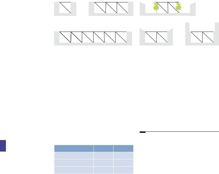
5.4.3 The public realm is defined by height as well as width – or, more accurately, the ratio of height to width. It is therefore recommended that the height of buildings (or mature trees where present in wider streets) is in proportion to the width of the intervening public space to achieve enclosure.The actual ratio depends on the type of street or open space being designed for.This is a fundamental urban design principle.The height- to-width enclosure ratios shown inTable 5.1 and illustrated in Fig. 5.4 can serve as a guide.
Table 5.1 Height-to-width ratios
|
Maximum |
Minimum |
Minor streets, e.g. mews |
1:1.5 |
1:1 |
Typical streets |
1:3 |
1:1.5 |
Squares |
1:6 |
1:4 |
5.4.4 The benefits of taller buildings, such as signifying locations of visual importance, adding variety, or simply accommodating larger numbers of dwellings, must be weighed against the possible disadvantages. These include
an overbearing relationship with the street, overshadowing of surrounding areas, and the need to provide more parking. Design mitigation techniques, such as wider footways, building recesses and street trees, can reduce the impact of taller buildings on their settings (Fig. 5.5).
5.4.5 Street length can have a significant effect on the quality of a place. Acknowledging and framing vistas and landmarks can help bring an identity to a neighbourhood and orientate users. However, long straights can encourage high traffic speeds, which should be mitigated through careful design (see Section 7.4 ‘Achieving appropriate traffic speeds’).
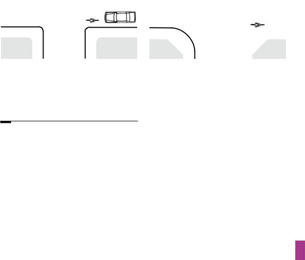
5.5Buildings at junctions
5.5.1 The arrangement of buildings and footways has a major influence on defining the space at a junction. It is better to design the junction on this basis rather than purely on vehicle movement (Fig. 5.6). In terms of streetscape, a wide carriageway with tight, enclosed corners makes a better junction than cutback corners with a sweeping curve.This might involve bringing buildings forward to the corner. Double-fronted buildings also have an important
role at corners. Junction treatments are explored in more detail in Chapter 7.
54 |
Manual for Streets |

a
Ben Castell, Llewelyn Davies Yeang
b
Ben Castell, Llewelyn Davies Yeang
Figure 5.5 Two streets demonstrating different levels of enclosure. Street (a) has a height-to-width ratio of approximately 1:3, enabling a pleasant living environment to be shared with functionality in the form of traffic movement and on-street parking, some of it angled. Street (b) has a height-to-width ratio of about 1:1.5. Again, this works well in urban design terms, but the need to accommodate on-street parking has meant that traffic is restricted to one-way movement.
Ben Castell, Llewelyn Davies Yeang
Figure 5.6 Wide, curved junctions reduce enclosure. In this example, the relationship between the buildings and the amenity space at the centre of the circus is diminished.
Manual for Streets |
55 |

15I. York, A. Bradbury, S. Reid, T. Ewings and R. Paradise (2007) The Manual for Streets:
Redefining Residential Street Design. TRL Report No. 661. Crowthorne: TRL.
5.6Backs and fronts
5.6.1 In general, it is recommended that streets are designed with the backs and fronts of houses and other buildings being treated differently.The basic tenet is ‘public fronts and private backs’.
Ideally, and certainly in terms of crime prevention, back gardens should adjoin other back gardens or a secure communal space. Front doors should open onto front gardens, small areas in front of the property, or streets.
a
b
5.6.2 The desirability of public fronts and private backs applies equally to streets with higher levels of traffic, such as those linking or providing access to residential areas. If such streets are bounded by back-garden fences or hedges, security problems can increase, drivers may be encouraged to speed, land is inefficiently used, and there
is a lack of a sense of place (Fig. 5.7). Research carried out for MfS15 shows that streets with direct frontage access to dwellings can operate safely with significant levels of traffic.
Llewelyn Davies Yeang
Figure 5.7 (a) and (b) Cul-de-sacs surrounded by a perimeter road that is fronted by back fences – no sense of place, no relationship with its surroundings, no quality, with streets designed purely for vehicles.
56 |
Manual for Streets |

16ODPM (2002) Planning Policy Guidance 17: Planning for Open Space, Sport and Recreation. London: TSO.
17Welsh Assembly Government (2006) Draft Technical Advice Note 16: Sport, Recreation and Open Space. Cardiff: NAfW.
5.7Designing streets as social spaces
5.7.1The public realm should be designed to encourage the activities intended to take place within it. Streets should be designed to accommodate a range of users, create visual interest and amenity, and encourage social
interaction.The place function of streets may equal or outweigh the movement function, as described in Chapter 2. This can be satisfied by providing a mix of streets of various dimensions, squares and courtyards, with associated ‘pocket parks’, play spaces, resting places and shelter. The key is to think carefully about the range of desirable activities for the environment being created, and to vary designs to suit each place in the network.
5.7.2High-quality open space is a key component of successful neighbourhoods. Local Development Frameworks, often supplemented by open space strategies and public realm strategies, should set out the requirements
for provision in particular localities. As with streets, parks and other open spaces should be accessible and be well overlooked16 (Wales: Refer to TAN 1617). Open spaces can aid urban cooling to help mitigate the effects of climate change.
5.8Other layout considerations
5.8.1 The layout of a new housing or mixed-use area will need to take account of factors other than street design and traffic provision. They include:
•the potential impact on climate change, such as the extent to which layouts promote sustainable modes of transport or reduce the need to travel;
•climate and prevailing wind, and the impact of this on building type and orientation;
•energy efficiency and the potential for solar gain by orientating buildings appropriately;
•noise pollution, such as from roads or railways;
•providing views and vistas, landmarks, gateways and focal points to emphasise urban structure, hierarchies and connections, as well as variety and visual interest;
•crime prevention, including the provision of defensible private and communal space, and active, overlooked streets (see Chapter 4); and
•balancing the need to provide facilities for young children and teenagers overlooked by housing, with the detrimental effects of noise and nuisance that may result.
Ben Castell, Llewelyn Davies Yeang
Figure 5.8 A contemporary interpretation of the terraced house, providing active frontage to the street and a small private buffer area.
5.8.2 Often satisfying one consideration will make it difficult to satisfy another, and invariably a balance has to be achieved. This is one of the reasons for agreeing design objectives at an early stage in the life of the scheme.
5.9Where streets meet buildings
5.9.1The space between the front of the building and the carriageway, footway or other public space needs to be carefully managed as it marks the transition from the public to the private realm. Continuous building lines are preferred as they provide definition to, and enclosure of, the public realm.They also make navigation by blind and partially-sighted people easier.
5.9.2For occupiers of houses, the amenity value of front gardens tends to be lower when compared to their back gardens and increased parking pressures on streets has meant that many householders have converted their front gardens to hard standing for car parking. However, this is not necessarily the most desirable outcome for street users in terms of amenity and quality of place, and can lead to problems with drainage. Where no front garden is provided, the setback of dwellings from the street is a key consideration in terms of:
Manual for Streets |
57 |

18Joint Committee on Mobility of Blind and Partially Sighted People (JCMBPS) (2002) Policy Statement on Walking Strategies. Reading: JCMBPS.
Llewelyn Davies Yeang
Figure 5.9 Trees, bollards, benches and the litter bin have the potential to clutter this residential square, but careful design means that they add to the local amenity.
•defining the character of the street;
•determining a degree of privacy;
•security space, providing a semi-private buffer which intruders would have to pass through, thus reducing opportunities for crime (Fig. 5.8);
•amenity space for plants or seating, etc.; and
•functional space for rubbish bins, external meters or storage, including secure parking for bicycles.
5.9.3Keeping garages and parking areas level with, or behind, the main building line can be aesthetically beneficial in townscape terms.
5.10Reducing clutter
5.10.1 Street furniture, signs, bins, bollards, utilities boxes, lighting and other items which tend to accumulate on a footway can clutter the streetscape. Clutter is visually intrusive and has adverse implications for many disabled people. The agencies responsible for such items and those who manage the street should consider ways of reducing their visual impact and impediment to users.
5.10.2Examples of reducing the impact include:18
• mounting streetlights onto buildings, or traffic signals onto lighting columns;
• locating service inspection boxes within buildings or boundary walls;
• specifying the location and orientation of inspection covers in the footway;
• ensuring that household bins and recycling containers can be stored off the footway; and
• designing street furniture to be in keeping with its surroundings (Fig. 5.9).
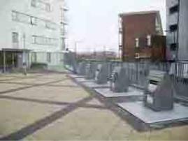
5.10.3Where terraced housing or flats are proposed, it can be difficult to find space for storing bins off the footway. In these circumstances, sub-surface or pop-up waste containers may be a practicable solution (Fig. 5.10).
5.11Local distinctiveness
5.11.1 Local identity and distinctiveness are important design considerations and can be strengthened by:
•relating the layout to neighbouring development (if it satisfies the basics of good urban design);
•involving the community early on in the design process;
58 |
Manual for Streets |

19For region-specific guidance, see English Heritage’s Streets for All series at www.englishheritage.org.uk.
Figure 5.10 Sub-surface recycling bins for communal use.
•using local materials (which may also be better environmentally);
•using grain, patterns and form sympathetic to the predominant vernacular styles (Fig. 5.11), or as established in local supplementary planning documents and/ or Character Assessment documents;19
•retaining historical associations; and
•engaging with utility companies to ensure that the design, quality and setting of their street furniture does not detract from the overall street design, view points and vistas.
 Lorraine Farrelly, University of Portsmouth
5.11.2 Village and Town Design Statements, which are based on enhancing local character and distinctiveness, can also be a useful tool.
5.12Planting
5.12.1Space for planting can be integrated into layout and building designs, and, wherever possible, located on private land or buildings (generous balconies, roof gardens, walls) or public land intended for adoption, including the highway.
5.12.2Planting adds value; it helps to soften the urban street-scene, creates visual and sensory interest, and improves the air quality and microclimate. It can also provide habitats for wildlife.The aromatic qualities or contrasting colours and textures of foliage are of value to all, and can assist the navigation of those with visual impairment. Flowers and fruit trees add seasonal variety.
5.12.3Planting can provide shade, shelter, privacy, spatial containment and separation. It can also be used to create buffer or security zones, visual barriers, or landmarks or gateway
features. Vegetation can be used to limit forward visibility to help reduce vehicle speeds.
Llewelyn Davies Yeang
Figure 5.11 The Orchard, Lechlade – new housing sympathetic to the local context.
Manual for Streets |
59 |
Una McGaughrin, Llewelyn Davies Yeang
Figure 5.12 Mature trees help to structure the space, while buildings are placed to create a sense of enclosure.
5.12.4Existing trees can occupy a substantial part of a development site and can have a major influence on layout design and use of the site, especially if they are protected by Tree Preservation Orders. Layouts poorly designed in relation to existing trees, or retaining trees of an inappropriate size, species or condition, may be resented by future occupants and create pressure to prune or remove them in the future. To reduce such problems, specialist advice is
needed in the design process. An arboriculturalist will help determine whether tree retention
can be successfully integrated within the new development, specify protection measures required during construction, and recommend appropriate replacements as necessary (Fig. 5.12).
5.12.5Sustainable planting will require the provision of:
• healthy growing conditions;
• space to allow growth to maturity with minimal intervention or management;
• species appropriate to a local sense of place and its intended function, and site conditions; and
•well-informed proposals for new planting (or the retention and protection of existing plants) and longer-term maintenance.
These proposals should be agreed with the adopting local or highway authority, trust, residents’ or community association or management company.
5.13Standing the test of time
5.13.1 Places need to look good and work well in the long term. Design costs are only a small percentage of the overall costs, but it is the quality of the design that makes the difference in creating places that will stand the test of time. Well-designed places last longer and are easier to maintain, thus the costs of the design element are repaid over time.The specification for materials and maintenance regimes should be written to provide high standards of durability and environmental performance. Maintenance should be straightforward and management regimes should ensure that there are clear lines of responsibility. These themes are covered further in Chapter 11.
60 |
Manual for Streets |

C
Detaileddesignissues

6 |
Street users’needs
David Millington Photography

1Disability Discrimination Act 2005. London: TSO.
2Department for Transport (2002) Inclusive Mobility A Guide to Best Practice on Access to Pedestrian and Transport Infrastructure. London:
Department for Transport.
3CABE (2006) The Principles of Inclusive Design (They include you). London: CABE.
4DETR (1999) Guidance on the Use of Tactile Paving Surfaces. London: TSO.
Chapter aims
•Promote inclusive design.
•Set out the various requirements of street users.
•Summarise the requirements for various types of motor vehicle.
6.1Introduction
6.1.1Street design should be inclusive. Inclusive design means providing for all people regardless of age or ability. There is a general duty for public authorities to promote equality under the Disability Discrimination Act 2005.1 There is also a specific obligation for those who design, manage and maintain buildings and public spaces to ensure that disabled people play a full part in benefiting from, and shaping, an inclusive built environment.
6.1.2Poordesigncanexacerbatetheproblems ofdisabledpeople–gooddesigncanminimisethem. Consultationwithrepresentativesofvarioususergroups,inparticulardisabledpeople,isimportantfor informingthedesignofstreets.Localaccessofficers canalsoassisthere.
6.1.3Designers should refer to Inclusive Mobility,2 The Principles of Inclusive Design3 and Guidance on the Use of Tactile Paving Surfaces (1999)4 in order to ensure that their designs are inclusive.
6.1.4If any aspect of a street unavoidably prevents its use by particular user groups, it is important that a suitable alternative is provided. For example, a safe cycling route to school may be inappropriate for experienced cyclist commuters, while a cycle route for commuters in the same transport corridor may be unsafe for use by children. Providing one as an alternative to the other overcomes these problems and ensures that the overall design is inclusive.
6.1.5This approach is useful as it allows for the provision of a specialised facility where there is considerable demand for it without disadvantaging user groups unable to benefit from it.
6.2Requirements for pedestrians and cyclists
6.2.1 When designing for pedestrians or cyclists, some requirements are common to both:
•routes should form a coherent network linking trip origins and key destinations, and they should be at a scale appropriate to the users;
•in general, networks should allow people to go where they want, unimpeded by street furniture, footway parking and other obstructions or barriers;
•infrastructure must not only be safe but also be perceived to be safe – this applies to both traffic safety and crime; and
•aesthetics, noise reduction and integration with surrounding areas are important – the environment should be attractive, interesting and free from graffiti and litter, etc.
6.3Pedestrians
6.3.1The propensity to walk is influenced not only by distance, but also by the quality of the walking experience. A 20-minute walk alongside a busy highway can seem endless, yet in a rich and stimulating street, such as in a town centre, it can pass without noticing. Residential areas can offer a pleasant walking experience if good quality landscaping, gardens or interesting architecture are present. Sightlines and visibility towards destinations or intermediate points are important for pedestrian way-finding and personal security, and they can help people with cognitive impairment.
6.3.2Pedestrians may be walking with purpose or engaging in other activities such as play, socialising, shopping or just sitting. For the purposes of this manual, pedestrians include wheelchair users and people pushing wheeled equipment such as prams.
6.3.3As pedestrians include people of all ages, sizes and abilities, the design of streets needs to satisfy a wide range of requirements. A street design which accommodates the needs of children and disabled people is likely to suit most, if not all, user types.
6.3.4Not all disability relates to difficulties with mobility. People with sensory or cognitive impairment are often less obviously disabled,
Manual for Streets |
63 |

5Department for Transport (1995) The Assessment of Pedestrian Crossings.
Local Transport Note
1/95. London: TSO.
6Department for Transport (1995) The Design of Pedestrian Crossings. Local Transport Note 2/95. London: TSO.
7County Surveyors’ Society/Department for Transport (2006) Puffin Good Practice Guide available to download from www.dft.gov.uk or www.cssnet.org.uk.
8Department for Transport (2005) Inclusive Mobility A Guide to Best Practice on Access to Pedestrian and Transport Infrastructure. London: Department for Transport.
Figure 6.1 West End of London 1884 – the block dimensions are of a scale that encourages walking.
so it is important to ensure that their needs are not overlooked. Legible design, i.e. design which makes it easier for people to work out where they are and where they are going, is especially helpful to disabled people. Not only does it minimise the length of journeys by avoiding wrong turns, for some it may make journeys possible to accomplish in the first place.
6.3.5The layout of our towns and cities has historically suited pedestrian movement (Fig. 6.1).
6.3.6Walkable neighbourhoods should be on an appropriate scale, as advised in Chapter 4. Pedestrian routes need to be direct and match desire lines as closely as possible. Permeable networks help minimise walking distances.
6.3.7Pedestrian networks need to connect with one another. Where these networks are separated by heavily-trafficked roads, appropriate surface level crossings should be provided where practicable. Footbridges and subways should be avoided unless local topography or other conditions make them necessary. The level changes and increased
distances involved are inconvenient, and they can be difficult for disabled people to use. Subways, in particular, can also raise concerns over personal security – if they are unavoidable, designers should aim to make them as short as possible, wide and well lit.
6.3.8The specific conditions in a street will determine what form of crossing is most relevant. All crossings should be provided with
tactile paving. Further advice on the assessment and design of pedestrian crossings is contained in Local Transport Notes 1/955 and 2/956 and the
Puffin Good Practice Guide.7
6.3.9Surface level crossings can be of a number of types, as outlined below:
•Uncontrolled crossings – these can be created by dropping kerbs at intervals along a link. As with other types of crossing, these should be matched to the pedestrian desire lines. If the crossing pattern is fairly random and there is
an appreciable amount of pedestrian activity, a minimum frequency of 100 m is recommended.8 Dropped kerbs should
64 |
Manual for Streets |

be marked with appropriate tactile paving and aligned with those on the other side of the carriageway.
•Informal crossings – these can be created through careful use of paving materials and street furniture to indicate a crossing place which encourages slow-moving traffic to give way to pedestrians (Fig. 6.2).
•Pedestrian refuges and kerb build-outs
– these can be used separately or in combination. They effectively narrow the carriageway and so reduce the crossing distance. However, they can create pinch-points for cyclists if the remaining gap is still wide enough for motor vehicles to squeeze past them.
•Zebra crossings – of the formal crossing types, these involve the minimum delay for pedestrians when used in the right situation.
•Signalised crossings – there are four types: Pelican, Puffin, Toucan and equestrian crossings. The Pelican crossing was the first to be introduced. Puffin crossings, which
have nearside pedestrian signals and a variable crossing time, are replacing Pelican crossings. They use pedestrian detectors to match the length of the crossing period to the time pedestrians take to cross. Toucan and equestrian crossings operate in a similar manner to Puffin crossings except that cyclists can also useToucan crossings, while equestrian crossings have a separate crossing for horse riders. Signalised crossings are preferred by blind or partially-sighted people.
6.3.10Obstructions on the footway should be minimised. Street furniture is typically sited on footways and can be a hazard for blind or partially-sighted people.
6.3.11Where it is necessary to break a road link in order to discourage through traffic, it is recommended that connectivity for pedestrians is maintained through the break unless there are compelling reasons to prevent it.
Andrew Cameron, WSP
Figure 6.2 Informal crossing, Colchester – although the chains and a lack of tactile paving are hazardous to blind or partially-sighted people.
Manual for Streets |
65 |
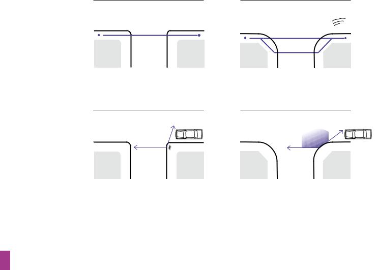
Small radius (eg. 1 metre)
•Pedestrian desire line (---) is maintained.
•Vehicles turn slowly (10 mph – 15 mph).
•Pedestrian does not have to look further behind to check for turning vehicles.
•Pedestrian can easily establish priority because vehicles turn slowly.
Figure 6.3 The effects of corner radii on pedestrians.
Large radius (eg. 7 metres)
•Pedestrian desire line deflected.
•Detour required to minimise crossing distance.
•Vehicles turn faster (20 mph – 30 mph).
Devon County Council
•Pedestrian must look further behind to check for fast turning vehicles.
•Pedestrian cannot normally establish priority against fast turning vehicles.
6.3.12Pedestrian desire lines should be kept as straight as possible at side-road junctions unless site-specific reasons preclude it. Small corner radii minimise the need for pedestrians to deviate from their desire line (Fig. 6.3). Dropped kerbs with the appropriate tactile paving should be provided at all side-road junctions where the carriageway and footway are at different levels. They should not be placed on curved sections of kerbing because this makes it difficult for blind or partiallysighted people to orientate themselves before crossing.
6.3.13With small corner radii, large vehicles may need to use the full carriageway width to turn. Swept-path analysis can be used to determine the minimum dimensions required. The footway may need to be strengthened locally in order to allow for larger vehicles occasionally overrunning the corner.
6.3.14Larger radii can be used without interrupting the pedestrian desire line if the footway is built out at the corners. If larger radii
encourage drivers to make the turn more quickly, speeds will need to be controlled in some way, such as through using a speed table at the junction.
6.3.15 The kerbed separation of footway and carriageway can offer protection to pedestrians, channel surface water, and assist blind or partially-sighted people in finding their way around, but kerbs can also present barriers to some pedestrians. Kerbs also tend to confer an implicit priority to vehicles on the carriageway. At junctions and other locations, such as school or community building entrances, there are benefits in considering bringing the carriageway up flush with the footway to allow people
to cross on one level (Fig. 6.4). This can be achieved by:
•raising the carriageway to footway level across the mouths of side roads; and
•providing a full raised speed-table at ‘T’ junctions and crossroads.
66 |
Manual for Streets |

Figure 6.4 Raised crossover, but located away from the desire line for pedestrians and therefore ignored – the crossover should be nearer the junction with, in this case, a steeper ramp for vehicles entering the side street.
Andrew Cameron, WSP |
Stuart Reid, TRL |
Figure 6.6 Uninviting pedestrian link – narrow, not well overlooked, unlit and deserted.
Tim Pharoah, Llewelyn Davies Yeang |
Andrew Cameron, WSP |
Figure 6.5 Inviting pedestrian link.
Figure 6.7 Overlooked shared route for pedestrians and vehicles, Poundbury, Dorset.
6.3.16The carriageway is usually raised using short ramps which can have a speed-reducing effect, but if the street is on a bus route, for example, a more gradual change in height may be more appropriate (Fig. 6.4). It is important that any such shared surface arrangements are designed for blind or partially-sighted people because conventional kerbs are commonly used to aid their navigation. Tactile paving
is required at crossing points regardless of whether kerbs are dropped or the carriageway is raised to footway level. Other tactile information may be required to compensate for kerb removal elsewhere.
6.3.17Pedestrians can be intimidated by traffic and can be particularly vulnerable to the fear of crime or anti-social behaviour. In order to encourage and facilitate walking, pedestrians need to feel safe (Figs 6.5 and 6.6).
6.3.18Pedestrians generally feel safe from crime where:
• their routes are overlooked by buildings with habitable rooms (Fig. 6.7);
• other people are using the street;
• there is no evidence of anti-social activity (e.g. litter, graffiti, vandalised street furniture);
• they cannot be surprised (e.g. at blind corners);
• they cannot be trapped (e.g. people can feel nervous in places with few entry and exit points, such as subway networks); and
• there is good lighting.
6.3.19Streets with high traffic speeds can make pedestrians feel unsafe. Designers should seek to control vehicle speeds to below 20 mph in residential areas so that pedestrians activity is not displaced. Methods of vehicle speed control are discussed in Chapter 7.
Manual for Streets |
67 |
2.1m
|
|
|
|
|
|
|
|
|
|
|
|
|
0.75 m |
|
|
0.9 m |
|
|
1.5 m |
|
|
1.2 m |
|||
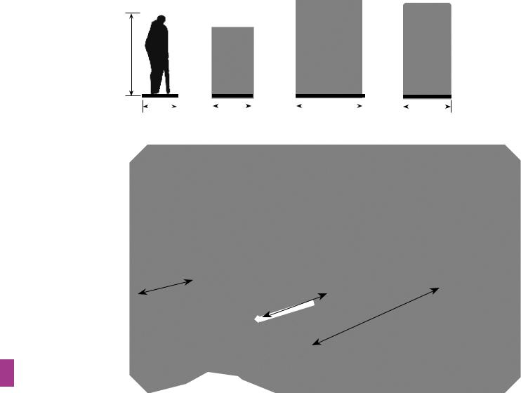
Footway 2m (min)
Stay/chat
2.5m or more
Play 4.0m or more
Figure 6.8 The footway and pedestrian areas provide for a range of functions which can include browsing, pausing, socialising and play.
Devon County Council
6.3.20 Inclusive Mobility gives guidance on design measures for use where there are steep slopes or drops at the rear of footways.
6.3.23 Footway widths can be varied between different streets to take account of pedestrian volumes and composition. Streets where people walk in groups or near schools
6.3.21Places for pedestrians may need to serve a or shops, for example, need wider footways.
variety of purposes, including movement in groups, children’s play and other activities (Fig. 6.8).
6.3.22 There is no maximum width for footways. In lightly used streets (such as those with a purely residential function), the minimum unobstructed width for pedestrians should generally be 2 m. Additional width should
be considered between the footway and a heavily used carriageway, or adjacent to gathering places, such as schools and shops. Further guidance on minimum footway widths is given in Inclusive Mobility.
In areas of high pedestrian flow, the quality of the walking experience can deteriorate unless sufficient width is provided. The quality of service goes down as pedestrian flow density increases. Pedestrian congestion through insufficient capacity should be avoided. It is inconvenient and may encourage people to step into the carriageway (Fig. 6.9).
6.3.24 Porch roofs, awnings, garage doors, bay windows, balconies or other building elements should not oversail footways at a height of less than 2.6 m.
68 |
Manual for Streets |

0.05 P/m2 0.20 P/m2 0.50 P/m2 0.90 P/m2
Figure 6.9 Diagram showing different densities of use in terms of pedestrians per square metre. Derived from Vorrang für Fussgänger 9.
Tim Pharoah, Llewelyn Davies Yeang
Figure 6.10 Poorly maintained tree obstructing the footway.
6.3.25Trees to be sited within or close to footways should be carefully selected so that their spread does not reduce pedestrian space below minimum dimensions for width and headroom (Fig. 6.10).
6.3.26Low overhanging trees, overgrown shrubs and advertising boards can be particularly hazardous for blind or partially-sighted people. Tapering obstructions, where the clearance under a structure reduces because the structure slopes
down (common under footbridge ramps), or the pedestrian surface ramps up, should be avoided or fenced off.
6.3.27 Designers should attempt to keep pedestrian (and cycle) routes as near to level as possible along their length and width, within the constraints of the site. Longitudinal gradients should ideally be no more than 5%, although topography or other circumstances may make this difficult to achieve (Fig. 6.11).
9Wissenschaft & Verkehr (1993) Vorrang für Fussgänger. Verkehrsclub Österreich.
Andrew Cameron, WSP
Figure 6.11 In some instances it may be possible to keep footways level when the carriageway is on a gradient, although this example deflects pedestrians wanting to cross the side road significantly from their desire lines.
Manual for Streets |
69 |
original footway profile
25 mm minimum upstand
Figure 6.12 Typical vehicle crossover.
back of footway 
900 mm minimum at normal footway crossfall (2.5% max.)
6.3.28Off-street parking often requires motorists to cross footways. Crossovers to private driveways are commonly constructed by ramping up from the carriageway over the whole width of the footway, simply because this is easier to construct.This is poor practice and creates inconvenient cross-falls for pedestrians. Excessive cross-fall causes problems for people pushing prams and can be particularly difficult to negotiate for people with a mobility impairment, including wheelchair users.
6.3.29Where it is necessary to provide vehicle crossovers, the normal footway cross-fall should be maintained as far as practicable from the back of the footway (900 mm minimum) (Fig. 6.12).
6.3.30Vehicle crossovers are not suitable as pedestrian crossing points. Blind or partiallysighted people need to be able to distinguish between them and places where it is safe to
cross. Vehicle crossovers should therefore have a minimum upstand of 25 mm at the carriageway edge. Where there is a need for a pedestrian crossing point, it should be constructed separately, with tactile paving and kerbs dropped flush with the carriageway.
6.3.31Surfaces used by pedestrians need to be smooth and free from trip hazards. Irregular surfaces, such as cobbles, are a barrier to some pedestrians and are unlikely to be appropriate for residential areas.
6.3.32Designs need to ensure that pedestrian areas are properly drained and are neither washed by runoff nor subject to standing water (Fig 6.13).
6.3.33Seating on key pedestrian routes should be considered every 100 m to provide rest points and to encourage street activity. Seating should ideally be located where there is good natural surveillance.
Stuart Reid, TRL |
Andrew Cameron, WSP |
Figure 6.13 Poor drainage at a pedestrian crossing place causes discomfort and inconvenience.
Figure 6.14 On-street cycling in Ipswich.
70 |
Manual for Streets |
Small radius (eg. 1 metre) |
Large radius (eg. 7 metres) |
|
|
|
|


 Devon County Council
•Cycle and car speeds compatible.
•Danger from fast turning vehicles cutting across cyclists.
Figure 6.15 The effect of corner radii on cyclists near turning vehicles.
6.4Cyclists
6.4.1Cyclists should generally be accommodated on the carriageway. In areas with low traffic volumes and speeds, there should not be any need for dedicated cycle lanes on the street (Fig. 6.14).
6.4.2Cycle access should always be considered on links between street networks which are not available to motor traffic. If an existing street is closed off, it should generally remain open to pedestrians and cyclists.
6.4.3Cyclists prefer direct, barrier-free routes with smooth surfaces. Routes should avoid the need for cyclists to dismount.
6.2.4 Cyclists are more likely to choose routes that enable them to keep moving. Routes that take cyclists away from their desire lines and require them to concede priority to side-road traffic are less likely to be used. Anecdotal evidence suggests that cyclists using cycle tracks running adjacent and parallel to a main road are particularly vulnerable when they cross the mouths of side roads and that, overall, these routes can be more hazardous to cyclists than the equivalent on-road route.
6.4.5 Cyclists are particularly sensitive to traffic conditions. High speeds or high volumes of traffic tend to discourage cycling. If traffic conditions are inappropriate for on-street cycling, the factors contributing to them need to be addressed, if practicable, to make on-street cycling satisfactory. This is described in more detail in Chapter 7.
6.4.6The design of junctions affects the way motorists interact with cyclists. It is recommended that junctions are designed to promote slow motor-vehicle speeds.This may include short corner radii as well as vertical deflections (Fig. 6.15).
6.4.7Where cycle-specific facilities, such
as cycle tracks, are provided, their geometry and visibility should be in accordance with the appropriate design speed. The design speed for a cycle track would normally be 30 km/h (20 mph), but reduced as necessary to as low as 10 km/h (6 mph) for short distances where cyclists would expect to slow down, such as on the approach to a subway. Blind corners are a hazard and should be avoided.
6.4.8Cyclists should be catered for on the road if at all practicable. If cycle lanes are installed, measures should be taken to prevent them from being blocked by parked vehicles. If cycle tracks are provided, they should be physically segregated from footways/footpaths if there is sufficient width available. However, there is generally little point in segregating a combined width of about 3.3 m or less. The fear of being struck by cyclists is a significant concern for many disabled people. Access officers and consultation groups should be involved in the decision-making process.
6.4.9Cycle tracks are more suited to leisure routes over relatively open spaces. In a built-up area, they should be well overlooked.The decision to light them depends on the circumstances of the site – lighting may not always be appropriate.
Manual for Streets |
71 |

6.4.10Like pedestrians, cyclists can be vulnerable to personal security concerns. Streets which meet the criteria described for pedestrians are likely to be acceptable to cyclists.
6.4.11The headroom over routes used by cyclists should normally be 2.7 m (minimum 2.4 m). The maximum gradients should generally be no more than 3%, or 5% maximum over a distance of 100 m or less, and 7% maximum over a distance of 30 m or less. However, topography may dictate the gradients, particularly if the route is in the carriageway.
6.4.12As a general rule, the geometry, including longitudinal profile, and surfaces employed on carriageways create an acceptable running surface for cyclists. The exception to this rule is the use of granite setts, or similar. These provide an unpleasant cycling experience due to the unevenness of the surface. They can prove to be particularly hazardous in the wet and when cyclists are turning, especially when giving hand signals at the same time. The conditions for cyclists on such surfaces can be improved if the line they usually follow is locally paved using larger slabs to provide a smoother ride.
6.5Public transport
6.5.1 This section concentrates on bus-based public transport as this is the most likely mode to be used for serving residential areas. Inclusive Mobility gives detailed guidance on accessible bus stop layout and design, signing, lighting, and design of accessible bus (and rail) stations and interchanges.
Public transport vehicles
6.5.2Purpose-built buses, from ‘hoppers’ to double-deckers, vary in length and height, but width is relatively fixed (Fig. 6.16).
6.5.3Streets currently or likely to be used by public transport should be identified in the design process, working in partnership with public transport operators.
6.5.4Bus routes and stops should form
key elements of the walkable neighbourhood. Designers and local authorities should try to ensure that development densities will be high enough to support a good level of service without long-term subsidy.
6.5.5In order to design for long-term viability, the following should be considered:
• streets serving bus routes should be reasonably straight. Straight routes also help passenger demand through reduced journey times and better visibility. Straight streets may, however, lead to excessive speeds. Where it is necessary to introduce traffic-calming features, designers should consider their potential effects on buses and bus passengers; and
• layouts designed with strong connections to the local highway network, and which avoid long one-way loops or long distances without passenger catchments, are likely to be more viable.
6.5.6Bus priority measures may be appropriate within developments to give more direct routeing or to assist buses in avoiding streets where delays could occur.
6.5.7Using a residential street as a bus route need not require restrictions on direct vehicular access to housing. Detailed requirements
for streets designated as bus routes can be determined in consultation with local public transport operators. Streets on bus routes should not generally be less than 6.0 m wide (although this could be reduced on short sections with good inter-visibility between opposing flows).The presence and arrangement of on-street parking, and the manner of its provision, will affect width requirements.
4.57 m
3.2 m
|
|
|
|
|
|
|
|
|
|
|
|
|
|
|
|
|
|
|
|
|
|
|
|
|
|
|
|
|
|
|
|
|
|
|
|
|
|
|
|
|
|
|
|
|
|
|
|
|
|
|
|
|
|
|
|
|
|
|
|
|
|
|
|
|
|
|
|
|
|
|
|
|
|
|
|
|
|
0.25 |
m |
|
2.5 m (max) |
|
0.25 m |
|||||||
|
|
|||||||||||
3.0 m
Figure 6.16 Typical bus dimensions
72 |
Manual for Streets |

Andrew Cameron, WSP
Figure 6.17 The bus lay-by facilitates the free movement of other vehicles, but it is inconvenient for pedestrians.
6.5.8 Swept-path analysis can be used to determine the ability of streets to accommodate large vehicles. Bus routes in residential areas are likely to require a more generous swept path to allow efficient operation. While it would be acceptable for the occasional lorry to have to negotiate a particular junction with care, buses need to be able to do so with relative ease. The level of provision required for the movement of buses should consider the frequency and the likelihood of two buses travelling in opposite directions meeting each other on a route.
Bus stops
6.5.9It is essential to consider the siting of public transport stops and related pedestrian desire lines at an early stage of design. Close co-operation is required between public transport operators, the local authorities and the developer.
6.5.10First and foremost, the siting of bus stops should be based on trying to ensure they can be easily accessed on foot. Their precise location will depend on other issues, such as the need to avoid noise nuisance, visibility requirements, and the convenience of pedestrians and cyclists. Routes to bus stops must be accessible by disabled people. For example, the bus lay-by in Fig. 6.17 deflects
pedestrians walking along the street from their desire line and the insufficient footway width at the bus stop hinders free movement.
6.5.11Bus stops should be placed near junctions so that they can be accessed by more than one route on foot, or near specific passenger destinations (schools, shops, etc.) but not so close as to cause problems at the
junction. On streets with low movement function (see Chapter 2), setting back bus stops from junctions to maximise traffic capacity should
be avoided.
6.5.12Bus stops should be high-quality places that are safe and comfortable to use. Consideration should be given to providing cycle parking at bus stops with significant catchment areas. Cycle parking should be designed and located so as not to create a hazard, or impede access for, disabled people.
6.5.13Footways at bus stops should be wide enough for waiting passengers while still allowing for pedestrian movement along the footway. This may require local widening at the stop.
6.5.14Buses can help to control the speed of traffic at peak times by preventing cars from overtaking. This is also helpful for the safety of passengers crossing after leaving the bus.
Manual for Streets |
73 |

Lorry
Van/mini bus
4.2 m
2.4 m
|
|
|
|
|
|
|
|
|
|
|
|
|
|
|
|
|
|
|
|
|
|
|
|
|
|
0.25 m |
|
2.5 m |
|
0.25 |
m |
|
|
0.2 |
m |
|
2.0 m |
|
0.2 |
m |
|
||||||||||
|
|
|
|
|
|
|
|
|
|
|
|
|
|
|
|
|
|
|
|
|
|
|
|
|
|
|
|
|
|
|
3.0 m |
|
|
|
|
|
|
|
|
|
|
|
|
|
2.4 m |
|
|
|
|
|
|
|
|
|
|
|
|
|
|
|
|
|
|
|
|
|
|
|
|
|
|
|
|
|
|
||
Figure 6.18 Private and commercial motor-vehicles – typical dimensions.
Family saloon
1.6 m
0.1 m |
1.8 m |
0.1 m |
2.0 m
6.6Private and commercial motor vehicles
6.6.1 Streets need to be designed to accommodate a range of vehicles from private cars, with frequent access requirements, to larger vehicles such as delivery vans and lorries, needing less frequent access (Fig. 6.18). Geometric design which satisfies the access needs of emergency service and waste collection vehicles will also cover the needs of private cars. However, meeting the needs of drivers in residential streets should not be to the detriment of pedestrians, cyclists and public transport users.The aim should be to achieve a harmonious mix of user types.
6.6.2Inaresidentialenvironment,flowisunlikely to be high enough to determine street widths, and the extent of parking provision (see Chapter 8) will depend on what is appropriate for the site.
6.6.3In some locations, a development may be based on car-free principles. For example, there are options for creating developments relatively free of cars by providing remotely sited parking (e.g. Greenwich Millennium Village, see Fig. 6.19) or by creating a wholly car-free development. Such approaches can have a significant effect on the design of residential streets and the way in which they are subsequently used.
Andrew Cameron, WSP
Figure 6.19 Greenwich Millennium Village. Cars can be parked on the street for a short time, after which they must be moved to a multi-storey car park.
74 |
Manual for Streets |

10Statutory Instrument 2000 No. 2531, The Building Regulations 2000. London: TSO. Part II, paragraph B5: Access and facilities for the fire service.
11Fire and Rescue Services Act 2004. London: TSO.
12Risk Reduction Plans required by the Welsh Assembly. See Welsh Assembly Government (2005) Fire and Rescue National Framework for Wales. Cardiff: NAfW.
6.7Emergency vehicles
6.7.1The requirements for emergency vehicles are generally dictated by the fire service requirements. Providing access for large fire appliances (including the need to be able to work around them where appropriate) will cater for police vehicles and ambulances.
6.7.2The Building Regulation requirement B5 (2000)10 concerns ‘Access and Facilities for the Fire Service’. Section 17, ‘Vehicle Access’, includes the following advice on access from the highway:
•there should be a minimum carriageway width of 3.7 m between kerbs;
•there should be vehicle access for a pump appliance within 45 m of single family houses;
•there should be vehicle access for a pump appliance within 45 m of every dwelling entrance for flats/maisonettes;
•a vehicle access route may be a road or other route; and
•fire service vehicles should not have to reverse more than 20 m.
6.7.3The Association of Chief Fire Officers has expanded upon and clarified these requirements as follows:
•a 3.7 m carriageway (kerb to kerb) is required for operating space at the scene of a fire. Simply to reach a fire, the access route could be reduced to 2.75 m over short distances, provided the pump appliance can get to within 45 m of dwelling entrances;
•if an authority or developer wishes to reduce the running carriageway width to below 3.7 m, they should consult the local Fire Safety Officer;
•the length of cul-de-sacs or the number of dwellings have been used by local authorities as criteria for limiting the size of a development served by a single access route. Authorities have often argued that the larger the site, the more likely it is that a single access could be blocked for whatever reason.The fire services adopt a less numbers-driven approach and consider each application based on a risk assessment for the site, and response time requirements. Since the introduction of the Fire and Rescue Services Act 2004,11 all regions have had to produce an Integrated Management Plan
setting out response time targets (Wales: Risk Reduction Plans12). These targets depend on the time required to get fire appliances to a particular area, together with the ease of movement within it. It is therefore possible that a layout acceptable to the Fire and Rescue Service (FRS) in one area, might be objected to in a more remote location;
•parked cars can have a significant influence on response times. Developments should have adequate provision for parking to reduce its impact on response times; and
•residential sprinkler systems are highly regarded by the FRS and their presence allows a longer response time to be used.
A site layout which has been rejected on the grounds of accessibility for fire appliances may become acceptable if its buildings are equipped with these systems.
6.8Service vehicles
6.8.1The design of local roads should accommodate service vehicles without allowing their requirements to dominate the layout. On streets with low traffic flows and speeds, it may be assumed that they will be able to use the full width of the carriageway to manoeuvre. Larger vehicles which are only expected to use a street infrequently, such as pantechnicons, need not be fully accommodated – designers could assume that they will have to reverse or undertake multipoint turns to turn around for the relatively
small number of times they will require access.
6.8.2Well-connected street networks have significant advantages for service vehicles. A shorter route can be used to cover a given
area, and reversing may be avoided altogether. They also minimise land-take by avoiding the need for wasteful turning areas at the ends of cul-de-sacs.
6.8.3However, some sites cannot facilitate such ease of movement (e.g. linear sites and those with difficult topography), and use cul-de-sacs to make the best use of the land available. For cul-de-sacs longer than 20 m, a turning area should be provided to cater for vehicles that will regularly need to enter the street. Advice on the design of turning areas is given in Chapter 7.
Manual for Streets |
75 |

13ODPM (2005) Planning Policy Statement 10: Planning for Sustainable Waste Management. London: TSO.
14Welsh Assembly Government (2002).
Planning Policy Wales. Cardiff: NAfW. Chapter 12, Infrastructure and Services.
15Welsh Assembly Government (2001)
Technical Advice Note 21: Waste. Cardiff: NAfW.
16British Standards Institute (BSI) (2005)
BS 5906: 2005 Waste Management in Buildings – Code of Practice. London: BSI.
17Statutory Instrument 2000 No. 2531, The Building Regulations 2000. London: TSO.
18BSI (2005) BS 5906: 2005 Waste Management in Buildings – Code of Practice. London: BSI.
Waste collection vehicles
6.8.4The need to provide suitable opportunities for the storage and collection of waste is a major consideration in the design of buildings, site layouts and individual streets. Storage may be complicated by the need to provide separate facilities for refuse and the various categories of recyclable waste. Quality of place will be significantly affected by the type of waste collection and management systems used, because they in turn determine the sort of vehicles that will need to gain access.
6.8.5Policy for local and regional waste planning bodies is set out in Planning Policy Statement 10: Planning for Sustainable Waste Management (PPS10)13 and its companion guide. PPS10 refers to design and layout
in new development being able to help secure opportunities for sustainable waste
management. Planning authorities should ensure that new developments make sufficient provision for waste management and promote designs and layouts that secure the integration of waste management facilities without adverse impact on the street scene (Wales: Refer to Chapter 12 of PPW14 and TAN 21: Waste15).
6.8.6The operation of waste collection services should be an integral part of street design and achieved in ways that do not compromise quality of place. Waste disposal and collection authorities and their contractors should take into account the geometry of streets across their area and the importance of securing quality of place when designing collection systems and deciding which vehicles are applicable. While it is always possible to design new streets to take the largest vehicle that could be manufactured, this would conflict with the desire to create quality places. It is neither necessary nor desirable to design new streets to accommodate larger waste collection
vehicles than can be used within existing streets in the area.
6.8.7Waste collection vehicles fitted with rear-mounted compaction units (Fig .6.20) are about the largest vehicles that might require regular access to residential areas. BS 5906:
200516 notes that the largest waste vehicles currently in use are around 11.6 m long, with
a turning circle of 20.3 m. It recommends a minimum street width of 5 m, but smaller widths are acceptable where on-street parking is discouraged. Swept-path analysis can be used to assess layouts for accessibility. Where achieving these standards would undermine quality of place, alternative vehicle sizes and/or collection methods should be considered.
6.8.8Reversing causes a disproportionately large number of moving vehicle accidents in the waste/recycling industry. Injuries to collection workers or members of the public by moving collection vehicles are invariably severe or fatal. BS 5906: 2005 recommends a maximum reversing distance of 12 m. Longer distances can be considered, but any reversing routes should be straight and free from obstacles or visual obstructions.
6.8.9Schedule 1, Part H of the Building Regulations (2000)17 define locations for the storage and collection of waste. The collection point can be on-street (but see Section 6.8.11), or may be at another location defined by the waste authority. Key points in the Approved Document to Part H are:
•residents should not be required to carry waste more than 30 m (excluding any vertical distance) to the storage point;
•waste collection vehicles should be able to get to within 25 m of the storage point (note, BS 5906: 200518 recommends shorter distances) and the gradient between the two should not exceed 1:12. There should be a maximum of three steps for waste
Tim Pharoah
Figure 6.20 Large waste collection truck in a residential street.
76 |
Manual for Streets |

Andrew Cameron, WSP
Figure 6.21 Refuse disposal point discharging into underground collection facility.
containers up to 250 litres, and none when larger containers are used (the Health and Safety Executive recommends that, ideally, there should be no steps to negotiate); and
•the collection point should be reasonably accessible for vehicles typically used by the waste collection authority.
6.8.10Based on these parameters, it may not be necessary for a waste vehicle to enter a cul-de-sac less than around 55 m in length, although this will involve residents and waste
collection operatives moving waste the maximum recommended distances, which is not desirable.
6.8.11BS 5906: 2005 provides guidance
and recommendations on good practice.The standard advises on dealing with typical weekly waste and recommends that the distance over which containers are transported by collectors should not normally exceed 15 m for two-wheeled containers, and 10 m for four-wheeled containers.
6.8.12 It is essential that liaison between the designers, the waste, highways, planning and building control authorities, and access officers, takes place at an early stage. Agreement is required
on the way waste is to be managed and in particular:
•methods for storing, segregating and collecting waste;
•the amount of waste storage required, based on collection frequency, and the volume and nature of the waste generated by the development; and
•the size of anticipated collection vehicles.
6.8.13 The design of new developments should not require waste bins to be left on the footway as they reduce its effective width. Waste bins on the footway pose a hazard for blind or partiallysighted people and may prevent wheelchair and pushchair users from getting past.
Recycling
6.8.14The most common types of provision for recycling (often used in combination) are:
• ‘bring’ facilities, such as bottle and paper banks, where residents leave material for recycling; and
• kerbside collection, where householders separate recyclable material for collection at the kerbside.
6.8.15‘Bring’ facilities need to be in accessible locations, such as close to community buildings, but not where noise from bottle banks, etc., can disturb residents.There needs to be enough room for the movement and operation of collection vehicles.
6.8.16Underground waste containers may be worth considering. All that is visible to the user is a ‘litter bin’ or other type of disposal point (Fig. 6.21). This collects in underground containers which are emptied by specially equipped vehicles. There were some 175 such systems in use in the UK in 2006.
6.8.17Kerbside collection systems generally require householders to store more than one type of waste container. This needs to
be considered in the design of buildings or external storage facilities.
6.8.18Designers should ensure that containers can be left out for collection without blocking the footway or presenting hazards to users.
Manual for Streets |
77 |