

ADS8339
www.ti.com |
SBAS677A –JUNE 2014 –REVISED OCTOBER 2014 |
Device Functional Modes (continued)
9.4.2 CS Mode for a 4-Wire Interface
This interface is similar to the CS mode for 3-wire interface except that SDI is controlled by the digital host. This section discusses in detail the interface option with and without a busy indicator.
9.4.2.1 4-Wire CS Mode Without a Busy Indicator
As mentioned previously, in order to select CS mode, SDI must be high at the time of the CONVST rising edge. Unlike in the 3-wire interface option, SDI is controlled by the digital host and functions like CS. As shown in Figure 50, SDI goes to a high level before the CONVST rising edge. When SDI is high, the CONVST rising edge selects CS mode, forces SDO to 3-state, samples the input signal, and the device enters the conversion phase.
In the 4-wire interface option, CONVST must be at a high level from the start of the conversion until all data bits are read. Conversion is done with the internal clock and continues regardless of the state of SDI. As a result, SDI (functioning as CS) can be brought low to select other devices on the board.
SDI must return to high before the minimum conversion time (tcnv_min in the Timing Requirements table) elapses.
CONVST |
|
|
|
|
|
|
|
|
SDI (CS) 1 |
|
|
|
|
|
|
|
|
|
t4 |
t5 |
|
|
|
|
|
|
|
|
|
|
|
|
|
|
|
SDI (CS) 2 |
|
|
|
|
|
|
|
|
|
|
tcnv_min |
|
|
|
|
|
|
|
|
tcnv |
|
|
tacq |
ten |
|
|
Phase |
Acquisition |
Conversion |
|
|
Acquisition |
|
|
|
|
|
|
|
|
||||
|
|
|
t2 |
|
tclkl |
|
|
|
SCLK |
|
1 |
2 |
15 |
16 |
17 |
18 |
|
|
|
t |
|
|
tclkh |
|
tdis |
|
|
|
en |
|
|
|
|
|
|
|
|
|
t |
3 |
tclk |
|
|
|
|
|
|
|
|
|
|
|
|
SDO |
|
D15 #1 |
D14 #1 |
D1 #1 |
D0 #1 |
D15 #2 |
D14 #2 |
|
|
t6 |
31 |
32 |
|
tdis |
D1 #2 |
D0 #2 |
Figure 50. Interface Timing Diagram: 4-Wire CS Mode Without a Busy Indicator
Copyright © 2014, Texas Instruments Incorporated |
Submit Documentation Feedback |
21 |
Product Folder Links: ADS8339
ADS8339
SBAS677A –JUNE 2014–REVISED OCTOBER 2014 |
www.ti.com |
Device Functional Modes (continued)
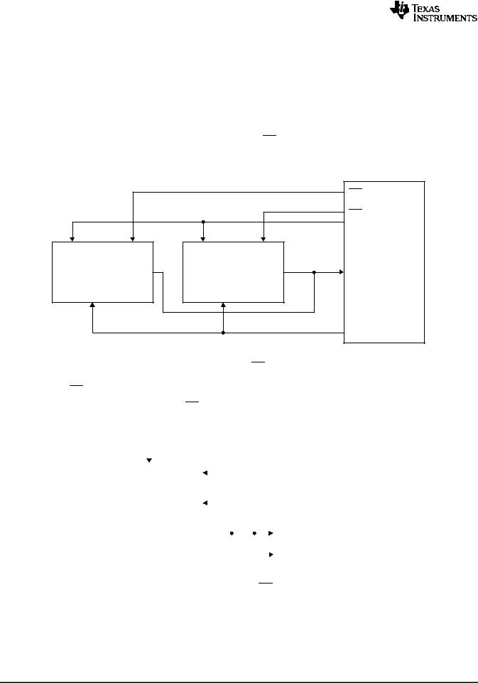
When the conversion is complete, the device enters the acquisition phase and powers down. An SDI falling edge can occur after the maximum conversion time (tcnv in the Timing Requirements table). Note that SDI must be high at the end of the conversion so that the device does not generate a busy indicator. The SDI falling edge brings SDO out of 3-state and the device outputs the MSB of the data. Subsequently, the device outputs the next lower data bits on every subsequent SCLK falling edge. SDO goes to 3-state after the 16th SCLK falling edge or when SDI (CS) is high, whichever occurs first. As shown in Figure 51, multiple devices can be chained on the same data bus. In this case, the second device SDI (functioning as CS) can go low after the first device data are read and the device 1 SDO is in 3-state.
Care must be taken so that CONVST and SDI are not both low at any time during the cycle.
|
|
|
|
CS1 |
|
|
|
|
CS2 |
|
|
|
|
CNV |
CONVST |
SDI |
CONVST |
SDI |
|
|
SDO |
|
SDO |
SDI |
SCLK |
|
SCLK |
|
|
|
|
|
|
CLK |
Device 1 |
|
Device 2 |
|
|
Digital Host
Figure 51. Connection Diagram: 4-Wire CS Mode Without a Busy Indicator
9.4.2.2 4-Wire CS Mode With a Busy Indicator
As mentioned previously, in order to select CS mode, SDI must be high at the time of the CONVST rising edge. In this mode of operation, the connection is made as shown in Figure 52.
|
|
|
|
|
|
|
|
|
|
|
|
|
|
|
|
|
|
|
|
|
|
|
|
|
|
|
CS |
||
|
|
|
|
|
|
|
|
|
|
|
||||
|
|
|
|
|
|
|
|
|
|
|
|
|
|
|
|
|
|
|
|
|
|
|
|
|
|
|
|
|
|
SDI |
CONVST |
|
|
|
|
|
|
|
|
|
CNV |
|||
|
|
|
|
|
|
|
|
|||||||
|
|
SCLK |
|
|
|
|
|
|
|
|
|
CLK |
||
|
|
|
+VBD |
|||||||||||
|
|
|
|
|
|
|
|
|||||||
|
|
SDO |
|
|
|
|
|
|
|
|
|
SDI |
||
|
|
|
|
|
|
|
|
|
|
|
||||
|
|
|
|
|
|
|
|
|
|
|
||||
|
|
|
|
|
|
|
|
|
|
|
|
|
|
|
|
|
Device |
|
|
|
|
|
|
|
|
|
|
|
|
|
|
|
|
|
|
|
|
|
|
|
IRQ |
|||
|
|
|
|
|
|
|
|
|
|
|
||||
|
|
|
|
|
|
|
|
|
|
|
|
|||
|
|
|
|
|
|
|
|
|
|
|
|
|
|
|
|
|
|
|
|
|
|
|
|
|
|
|
Digital Host |
||
Figure 52. Connection Diagram: 4-Wire CS Mode With a Busy Indicator
22 |
Submit Documentation Feedback |
Copyright © 2014, Texas Instruments Incorporated |
Product Folder Links: ADS8339