

Правила Кодексы / МАРПОЛ / 212(63)
.pdfMEPC 63/23
Annex 8, page 1
ANNEX 8
RESOLUTION MEPC.212(63)
Adopted on 2 March 2012
2012 GUIDELINES ON THE METHOD OF CALCULATION OF THE ATTAINED ENERGY EFFICIENCY DESIGN INDEX (EEDI) FOR NEW SHIPS
THE MARINE ENVIRONMENT PROTECTION COMMITTEE,
RECALLING article 38(a) of the Convention on the International Maritime Organization concerning the functions of the Marine Environment Protection Committee (the Committee) conferred upon it by international conventions for the prevention and control of marine pollution,
RECALLING ALSO that, at its sixty-second session, the Committee adopted, by resolution MEPC.203(62), amendments to the annex of the Protocol of 1997 to amend the International Convention for the Prevention of Pollution from Ships, 1973, as modified by the Protocol of 1978 relating thereto (inclusion of regulations on energy efficiency for ships in MARPOL Annex VI),
NOTING the amendments to MARPOL Annex VI adopted at its sixty-second session by inclusion of a new chapter 4 for regulations on energy efficiency for ships, are expected to enter into force on 1 January 2013 upon their acceptance on 1 July 2012,
NOTING ALSO that regulation 20 (Attained EEDI) of MARPOL Annex VI, as amended, requires that the Energy Efficiency Design Index shall be calculated taking into account the guidelines developed by the Organization,
RECOGNIZING that the amendments to MARPOL Annex VI requires the adoption of relevant guidelines for smooth and uniform implementation of the regulations and to provide sufficient lead time for industry to prepare,
HAVING CONSIDERED, at its sixty-third session, the draft 2012 Guidelines on the method of calculation of the attained Energy Efficiency Design Index (EEDI) for new ships,
1.ADOPTS the 2012 Guidelines on the method of calculation of the attained Energy Efficiency Design Index (EEDI) for new ships, as set out at annex to the present resolution;
2.INVITES Administrations to take the annexed Guidelines into account when developing and enacting national laws which give force to and implement provisions set forth in regulation 20 of MARPOL Annex VI, as amended;
3.REQUESTS the Parties to MARPOL Annex VI and other Member Governments to bring the annexed Guidelines related to the Energy Efficiency Design Index (EEDI) to the attention of shipowners, ship operators, shipbuilders, ship designers and any other interested groups;
4.AGREES to keep these Guidelines under review in light of the experience gained; and
5.REVOKES the Interim Guidelines circulated by MEPC.1/Circ.681, as from this date.
I:\MEPC\63\23.doc

MEPC 63/23
Annex 8, page 2
ANNEX
2012 GUIDELINES ON THE METHOD OF CALCULATION OF THE ATTAINED ENERGY EFFICIENCY DESIGN INDEX (EEDI) FOR NEW SHIPS
CONTENTS
1Definitions
2Energy Efficiency Design Index (EEDI) including the equation
2.1CF ; conversion factor between fuel consumption and CO2 emission
2.2Vref ; ship speed
2.3Capacity
2.3.1Bulk carriers, tankers, gas carriers, ro-ro cargo ships and general cargo ships
2.3.2Passenger ships and ro-ro passenger ships
2.3.3Containerships
2.4Deadweight
2.5P ; Power of main and auxiliary engines
2.5.1PME ; power of main engines
2.5.2PPTO ; shaft generator
2.5.3PPTI ; shaft motor
2.5.4Peff ; output of innovative mechanical energy efficient
technology
2.5.5PAEeff ; auxiliary power reduction
2.5.6PAE ; power of auxiliary engines
2.6Vref, Capacity and P
2.7SFC ; Specific fuel consumption
2.8fj ; Correction factor for ship specific design elements
2.8.1fj ; ice-class ships
2.8.2fj ; shuttle tankers
2.8.3fj ; other ship types
2.9fw ; Weather factor
2.10feff ; Availability factor of innovative energy efficiency technology
2.11fi ; Capacity factor
2.11.1fi ; ice-class ships
2.11.2fi ; ship specific voluntary structural enhancement
2.11.3fi ; bulk carriers and oil tankers under Common Structural
Rules (CSR)
2.11.4fi ; other ship types
2.12fc ; Cubic capacity correction factor
2.12.1fc ; chemical tankers
2.12.2fc ; LNG carriers
2.13Lpp ; Length between perpendiculars
APPENDIX 1 A generic and simplified power plant
APPENDIX 2 Guidelines for the development of electric power tables for EEDI (EPT-EEDI)
I:\MEPC\63\23.doc

MEPC 63/23
Annex 8, page 3
1 Definitions
MARPOL means the International Convention for the Prevention of Pollution from Ships, 1973, as modified by the Protocol of 1978 relating thereto, as amended.
For the purpose of these Guidelines, the definitions in "REGULATIONS ON ENERGY EFFICIENCY FOR SHIPS" (RESOLUTION MEPC. 203(62)) apply.
2 Energy Efficiency Design Index (EEDI)
The attained new ship Energy Efficiency Design Index (EEDI) is a measure of ships energy efficiency (g/t*nm) and calculated by the following formula:
|
n |
nME |
|
|
|
n |
|
nPTI |
|
neff |
|
|
|
neff |
|
|
|
|
|
PME(i) CFME(i) SFCME(i) |
PAE CFAE SFCAE |
|
fj |
|
PPTI(i) |
|
|
|
|||||
|
fj |
|
feff (i) PAEeff (i) CFAE SFCAE |
|
feff (i) Peff (i) CFME SFCME |
|||||||||||
|
|
|
|
|
|
|
|
|
|
|
||||||
|
j1 |
|
i1 |
|
|
|
j1 |
|
i1 |
|
i1 |
|
|
i1 |
|
|
fi fc Capacity fw Vref
*If part of the Normal Maximum Sea Load is provided by shaft generators,
SFCME and CFME may – for that part of the power – be used instead of SFCAE and CFAE
**In case of PPTI(i)>0, the average weighted value of (SFCME . CFME) and (SFCAE . CFAE ) to be used for calculation of Peff
Note: This formula may not be able to apply to diesel-electric propulsion, turbine propulsion or hybrid propulsion system.
Where:
.1 CF is a non-dimensional conversion factor between fuel consumption measured in g and CO2 emission also measured in g based on carbon content. The subscripts MEi and AEi refer to the main and auxiliary engine(s) respectively. CF corresponds to the fuel used when determining SFC listed in the applicable test report included in a Technical File as defined in paragraph 1.3.15 of NOx Technical Code ("test report included in a NOx technical file" hereafter). The value of CF is as follows:
|
Type of fuel |
Reference |
Carbon |
CF |
|
|
content |
(t-CO2/t-Fuel) |
|||
|
|
|
|||
1 |
Diesel/Gas Oil |
ISO 8217 Grades DMX through |
0.8744 |
3.206 |
|
DMB |
|||||
|
|
|
|
||
2 |
Light Fuel Oil (LFO) |
ISO 8217 Grades RMA through |
0.8594 |
3.151 |
|
RMD |
|||||
3 |
Heavy Fuel Oil |
ISO 8217 Grades RME through |
0.8493 |
3.114 |
|
|
(HFO) |
RMK |
|||
|
|
|
|||
4 |
Liquefied Petroleum |
Propane |
0.8182 |
3.000 |
|
|
Gas (LPG) |
Butane |
0.8264 |
3.030 |
|
5 |
Liquefied Natural |
|
0.7500 |
2.750 |
|
|
Gas (LNG) |
|
|||
|
|
|
|
I:\MEPC\63\23.doc

MEPC 63/23
Annex 8, page 4
.2 Vref is the ship speed, measured in nautical miles per hour (knot), on deep water in the condition corresponding to the Capacity as defined in paragraphs 2.3.1 and 2.3.3 (in case of passenger ships and ro-ro passenger ships, this condition should be summer load draught as provided in paragraph 2.4) at the shaft power of the engine(s) as defined in paragraph 2.5 and assuming the weather is calm with no wind and no waves.
.3 Capacity is defined as follows:
.1 For bulk carriers, tankers, gas tankers, ro-ro cargo ships, general cargo ships, refrigerated cargo carrier and combination carriers, deadweight should be used as Capacity.
.2 For passenger ships and ro-ro passenger ships, gross tonnage in accordance with the International Convention of Tonnage Measurement of Ships 1969, Annex I, regulation 3 should be used as Capacity.
.3 For containerships, 70 per cent of the deadweight (DWT) should be used as Capacity. EEDI values for containerships are calculated as follows:
.1 attained EEDI is calculated in accordance with the EEDI formula using 70 per cent deadweight for Capacity.
.2 estimated index value in the Guidelines for calculation of the reference line is calculated using 70 per cent deadweight as:
NME
190 PMEi 215 PAE
Estimated Index Value 3.1144 |
i 1 |
|
70%DWT Vref |
.3 parameters a and c for containerships in Table 2 of regulation 21 of MARPOL Annex VI are determined by plotting the estimated index value against 100 per cent deadweight i.e. a=174.22 and c=0.201 were determined.
.4 required EEDI for a new containership is calculated using 100 per cent deadweight as:
Required EEDI = (1-X/100) · a · 100% deadweight –c
Where X is the reduction factor (in percentage) in accordance with Table 1 in regulation 21 of MARPOL Annex VI relating to the applicable phase and size of new containership.
.4 Deadweight means the difference in tonnes between the displacement of a ship in water of relative density of 1,025 kg/m3 at the summer load draught and the lightweight of the ship. The summer load draught should be taken as the maximum summer draught as certified in the stability booklet approved by the Administration or an organization recognized by it.
I:\MEPC\63\23.doc

MEPC 63/23
Annex 8, page 5
.5 P is the power of the main and auxiliary engines, measured in kW. The subscripts ME and AE refer to the main and auxiliary engine(s), respectively.
The summation on i is for all engines with the number of engines (nME). (See diagram in appendix 1.)
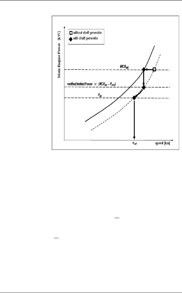
.1 PME(i) is 75 per cent of the rated installed power (MCR*) for each main engine (i).
The influence of additional shaft power take off or shaft power take in is defined in the following paragraphs.
.2 Shaft generator
In case where shaft generator(s) are installed, PPTO(i) is 75 per cent of the rated electrical output power of each shaft generator.
For calculation of the effect of shaft generators two options are available:
Option 1:
.1 The maximum allowable deduction for the calculation of
PME(i) is to be no more than PAE as defined in paragraph 2.5.6. For this case, PME(i) is calculated as:
PME(i) = 0.75 MCRME(i) PPTO(i)
or
Option 2:
.2 Where an engine is installed with a higher rated power output than that which the propulsion system is limited to
by verified technical means, then the value of PME(i) is 75 per cent of that limited power for determining the
reference speed, Vref and for EEDI calculation.
*The value of MCR specified on the EIAPP certificate should be used for calculation. If the main engines are not required to have an EIAPP certificate, the MCR on the nameplate should be used.
I:\MEPC\63\23.doc
MEPC 63/23
Annex 8, page 6
The following figure gives guidance for determination of PME(i) :
.3 Shaft motor
In case where shaft motor(s) are installed, PPTI(i) is 75 per cent of the rated power consumption of each shaft motor divided by the
weighted average efficiency of the generator(s).
The propulsion power at which Vref is measured, is:
PME(i) PPTI (i),Shaft
Where:
PPTI (i),Shaft PPTI (i) PTI (i) Gen
PTI (i) is the efficiency of each shaft motor installed
Gen is the weighted average efficiency of the generator(s)
Where the total propulsion power as defined above is higher than 75 per cent of the power the propulsion system is limited to by verified technical means, then 75 per cent of the limited power is to be used as the total propulsion power for determining the reference speed, Vref and for EEDI calculation.
I:\MEPC\63\23.doc

MEPC 63/23
Annex 8, page 7
In case of combined PTI/PTO, the normal operational mode at sea will determine which of these to be used in the calculation.
Note: The shaft motor's chain efficiency may be taken into consideration to account for the energy losses in the equipment from the switchboard to the shaft motor, if the chain efficiency of the shaft motor is given in a verified document.
.4 Peff(i) is the output of the innovative mechanical energy efficient technology for propulsion at 75 per cent main engine power.
Mechanical recovered waste energy directly coupled to shafts need not be measured, since the effect of the technology is directly reflected in the Vref.
In case of a ship equipped dual-fuel engine or a number of
engines, the CFME and SFCME should be the power weighted average of all the main engines.
.5 PAEeff (i) is the auxiliary power reduction due to innovative electrical energy efficient technology measured at PME(i).
.6 PAE is the required auxiliary engine power to supply normal maximum sea load including necessary power for propulsion machinery/systems and accommodation, e.g. main engine pumps, navigational systems and equipment and living on board, but excluding the power not for propulsion machinery/systems, e.g. thrusters, cargo pumps, cargo gear, ballast pumps, maintaining cargo, e.g. reefers and cargo hold fans, in the condition where the ship engaged in voyage at the speed (Vref) under the condition as mentioned in paragraph 2.2.
.1 For ships with a main engine power of 10,000 above, PAE is defined as:
|
|
nPTI |
|
|
nME |
PPTI(i) |
|
PAE(MCRME 10000KW) |
0.025( MCRMEi |
i 1 |
|
0.75 |
|||
|
i 1 |
||
|
|
||
|
|
|
kW or
) 250
.2 For ships with a main engine power below 10,000 kW, PAE is defined as:
|
|
nPTI |
|
|
|
nME |
PPTI(i) |
|
|
PAE(MCRME 10000KW) |
0.05 ( MCRMEi |
i 1 |
) |
|
0.75 |
||||
|
i 1 |
|
||
|
|
|
||
|
|
|
|
I:\MEPC\63\23.doc

MEPC 63/23
Annex 8, page 8
.3 For ship where the PAE value calculated by paragraph 2.5.6.1 or 2.5.6.2 is significantly different from the total power used at normal seagoing, e.g. in cases of passenger ships (see NOTE under the formula of EEDI), the PAE value should be estimated by the consumed electric power (excluding propulsion) in conditions when the ship is engaged in a voyage at reference speed (Vref) as given in the electric power table1, divided by the average efficiency of the generator(s) weighted by power (see appendix 2).
.6 Vref, Capacity and P should be consistent with each other.
.7 SFC is the certified specific fuel consumption, measured in g/kWh, of the
engines. The subscripts ME(i) and AE(i) refer to the main and auxiliary engine(s), respectively. For engines certified to the E2 or E3 test cycles of the NOx
Technical Code 2008, the engine Specific Fuel Consumption (SFCME(i)) is that recorded in the test report included in a NOx technical file for the engine(s)
at 75 per cent of MCR power of its torque rating. For engines certified to the D2 or C1 test cycles of the NOx Technical Code 2008, the engine
Specific Fuel Consumption (SFCAE(i)) is that recorded on the test report included in a NOx technical file at the engine(s) 50 per cent of MCR power
or torque rating.
The SFC should be corrected to the value corresponding to the ISO standard reference conditions using the standard lower calorific value of the fuel oil (42,700kJ/kg), referring to ISO 15550:2002 and ISO 3046-1:2002.
For ships where the PAE value calculated by paragraphs 2.5.6.1 and 2.5.6.2 is significantly different from the total power used at normal seagoing, e.g. conventional passenger ships, the Specific Fuel Consumption (SFCAE) of the auxiliary generators is that recorded in the test report included in a NOx technical file for the engine(s) at 75 per cent of MCR power of its torque rating.
SFCAE is the power-weighted average among SFC AE(i) of the respective engines i.
For those engines which do not have a test report included in a NOx technical file because its power is below 130 kW, the SFC specified by the manufacturer and endorsed by a competent authority should be used.
At the design stage, in case of unavailability of test report in the NOx file, the SFC specified by the manufacturer and endorsed by a competent authority should be used.
For LNG driven engines of which SFC is measured in kJ/kWh should be corrected to the SFC value of g/kWh using the standard lower calorific value of the LNG (48,000 kJ/kg), referring to the 2006 IPCC Guidelines.
1The electric power table should be examined and validated by the verifier. Where ambient conditions affect any electrical load in the power table the contractual ambient conditions leading to the maximum design electrical load of the installed system for the ship in general should apply.
I:\MEPC\63\23.doc

MEPC 63/23
Annex 8, page 9
.8 fj is a correction factor to account for ship specific design elements:
|
.1 |
|
|
The power correction factor, fj, for ice-classed ships should be |
||||||||
|
|
|
|
|
|
|
taken as the greater value of fj0 and fj,min as tabulated in Table 1 |
|||||
|
|
|
|
|
|
|
but not greater than fj,max = 1.0. |
|
|
|||
|
|
|
|
|
|
|
For further information on approximate correspondence between |
|||||
|
|
|
|
|
|
|
ice classes, see HELCOM Recommendation 25/72. |
|
||||
|
|
|
|
Table 1: Correction factor for power f j for ice-classed ships |
|
|||||||
|
|
|
|
|
|
|
|
|
|
|
|
|
Ship type |
|
|
|
fj0 |
|
|
|
|
|
fj,min depending on the ice class |
|
|
|
|
|
|
|
|
|
|
|
IA Super |
IA |
IB |
IC |
|
|
|
|
0.308L |
1.920 |
|
|
|
|
|
|
|
Tanker |
|
|
|
PP |
|
|
|
|
0.30 |
0.21 |
0.13 |
0.06 |
|
|
|
nME |
|
|
|
|
|||||
|
|
|
PME(i) |
0.15 LPP |
0.27LPP |
0.45LPP |
0.70LPP |
|||||
|
|
|
|
|
|
|
|
|||||
|
|
|
|
i1 |
|
|
|
|
|
|
|
|
|
|
|
0.639L |
1.754 |
|
|
|
|
|
|
||
|
|
|
|
PP |
0.09 |
0.07 |
0.04 |
0.02 |
||||
Bulk carrier |
|
|
|
nME |
|
|
|
|
||||
|
|
|
PME(i) |
0.47LPP |
0.58LPP |
0.73LPP |
0.87LPP |
|||||
|
|
|
|
|
|
|
|
|||||
|
|
|
|
i 1 |
|
|
|
|
|
|
|
|
|
|
0.0227 L |
2.483 |
|
|
|
|
|
||||
General |
|
|
|
PP |
0.31L 0.16 |
0.43L 0.12 |
0.56L 0.09 |
0.67L 0.07 |
||||
|
|
|
nME |
|
|
|
|
|||||
cargo ship |
|
|
|
PME(i) |
PP |
PP |
PP |
PP |
||||
|
|
|
|
|
|
|
|
|
||||
|
|
|
|
i 1 |
|
|
|
|
|
|
|
|
|
.2 |
|
|
The factor fj, for shuttle tankers with propulsion redundancy should |
||||||||
|
|
|
|
|
|
|
be fj = 0.77. This correction factors applies to shuttle tankers with |
|||||
propulsion redundancy between 80,000 and 160,000 deadweight. The Shuttle Tankers with Propulsion Redundancy are tankers used for loading of crude oil from offshore installations equipped with dual-engine and twin-propellers need to meet the requirements for dynamic positioning and redundancy propulsion class notation.
.3 For other ship types, fj should be taken as 1.0.
.9 fw is a non-dimensional coefficient indicating the decrease of speed in representative sea conditions of wave height, wave frequency and wind speed (e.g. Beaufort Scale 6), and is determined as follows:
.1 for attained EEDI calculated under regulations 20 and 21 of MARPOL Annex VI, fw is 1.00;
.2 when fw is calculated according to the subparagraph .2.1 or .2.2 below, the value for attained EEDI calculated by the formula in paragraph 2 using the obtained fw should be referred to as "attained EEDIweather";
.1 fw can be determined by conducting the ship specific simulation on its performance at representative sea conditions. The simulation methodology should be based on the Guidelines developed by the Organization and the
2 |
HELCOM Recommendation 25/7 may be found at http://www.helcom.fi. |
|
I:\MEPC\63\23.doc

MEPC 63/23
Annex 8, page 10
method and outcome for an individual ship should be verified by the Administration or an organization recognized by the Administration; and
.2 in cases where a simulation is not conducted, fw should be taken from the "Standard fw " table/curve. A "Standard fw " table/curve is provided in the Guidelines3 for each ship type defined in paragraph 1, and expressed as a function of Capacity (e.g. deadweight). The "Standard fw " table/curve is based on data of actual speed reduction of as many existing ships as possible under the representative sea condition.
fw and attained EEDIweather, if calculated, with the representative sea conditions under which those values are determined, should be indicated in
the EEDI Technical File to make a distinction with the attained EEDI calculated under regulations 20 and 21 of MARPOL Annex VI.
.10 feff(i) is the availability factor of each innovative energy efficiency technology. feff(i) for waste energy recovery system should be one (1.0)4.
.11 fi is the capacity factor for any technical/regulatory limitation on capacity, and should be assumed to be one (1.0) if no necessity of the factor is granted.
|
.1 |
|
|
The capacity correction factor, fi, for ice-classed ships should be |
|||||||||||||
|
|
|
|
|
|
taken as the lesser value of fi0 and fi,max as tabulated in Table 2, but |
|||||||||||
|
|
|
|
|
|
not less than fi,min = 1.0. For further information on approximate |
|||||||||||
|
|
|
|
|
|
correspondence |
between |
ice |
classes, |
see |
HELCOM |
||||||
|
|
|
|
|
|
Recommendation 25/75. |
|
|
|
|
|
|
|
||||
|
|
|
|
|
|
Table 2: Capacity correction factor fi for ice-classed ships |
|
|
|||||||||
|
|
|
|
|
|
|
|
|
|
|
|
|
|
|
|||
Ship type |
|
|
fi0 |
|
|
|
|
|
|
fi,max depending on the ice class |
|
|
|||||
|
|
|
|
|
|
|
IA Super |
IA |
|
IB |
|
|
IC |
|
|||
Tanker |
|
|
0.00138 LPP |
3.331 |
|
|
2.10L |
PP |
0.11 |
1.71L |
0.08 |
1.47L |
PP |
0.06 |
|
1.27L |
0.04 |
|
|
|
|
|
|
|
|||||||||||
|
|
|
capacity |
|
|
|
|
|
PP |
|
|
|
|
PP |
|
||
|
|
|
|
|
|
|
|
|
|
|
|
|
|
|
|
|
|
|
|
0.00403 L |
3.123 |
|
|
|
|
0.11 |
1.80L |
0.09 |
|
|
0.07 |
|
1.31L |
0.05 |
|
Bulk carrier |
|
|
PP |
|
|
|
2.10L |
1.54L |
|
|
|||||||
|
|
|
|
|
|
|
|
||||||||||
|
|
|
capacity |
|
|
|
PP |
|
PP |
PP |
|
|
PP |
|
|||
|
|
|
|
|
|
|
|
|
|
|
|
|
|
|
|
|
|
General |
|
0.0377 LPP 2.625 |
|
|
2.18L |
|
0.11 |
1.77L |
0.08 |
1.51L 0.06 |
|
1.28L |
0.04 |
||||
cargo ship |
|
|
capacity |
|
|
|
PP |
|
PP |
|
PP |
|
|
PP |
|
||
|
|
|
|
|
|
|
|
|
|
|
|
||||||
|
|
|
|
|
|
|
|
|
|
|
|
|
|
|
|
||
Containership |
|
0.1033 LPP 2.329 |
|
|
2.10L |
PP |
0.11 |
1.71L |
0.08 |
1.47L |
PP |
0.06 |
|
1.27L |
0.04 |
||
|
|
|
capacity |
|
|
|
|
|
PP |
|
|
|
|
PP |
|
||
|
|
|
|
|
|
|
|
|
|
|
|
|
|
|
|
|
|
Gas carrier |
|
|
0.0474 LPP2.590 |
|
|
1.25 |
|
2.10L |
0.12 |
1.60L |
|
0.08 |
|
1.25L |
0.04 |
||
|
|
|
capacity |
|
|
|
|
|
|
PP |
PP |
|
|
PP |
|
||
|
|
|
|
|
|
|
|
|
|
|
|
|
|
|
|
|
|
Note: containership capacity is defined as 70% of the DWT.
3Guidelines for the calculation of the coefficient fw for the decrease of ship speed in respective sea conditions will be developed.
4EEDI calculation should be based on the normal sea-going condition outside Emission Control Area designated under paragraph 6 of regulation 13 in MARPOL ANNEX VI.
5HELCOM Recommendation 25/7 may be found at http://www.helcom.fi.
I:\MEPC\63\23.doc