


GrafNav |
Chapter 2 |
|
|
|
|
2.4.7Objects
This command brings up the Object Menu for all of the epochs, static sessions, KAR fixes, features, stations, and RTK data in the project. The Object Menu can also be activated by right-clicking on an epoch of interest in the map window. This displays the features and epochs around the selected epoch.
The options that are available with the buttons on the right-hand side of the window are listed in the shaded box.
Static Sessions
Be aware of the antenna height when processing static sessions or features within a data set. For static sessions, determine antenna height in the following order:
1.Use manual override. To override an antenna height, select the static session from the Object Menu and click the Edit button. Manual override is disabled by default.
2.Use station feature antenna height. The antenna height of a given feature is read from the STA file. If you need to edit it, use the Feature Editor menu. This method of antenna height determination applies only if the feature is found within the static session. See
Section 2.4.7, on Page 57 for details.
3.Use remote antenna height. See Section 2.3.7, on Page 37 for help changing the remote antenna settings.
GrafNav requires the vertical offset between the marker and L1 phase centre. Most often the distance between the marker and the ARP (or measurement mark) are measured and a correct antenna model is required to add the offset from the ARP to the L1 phase centre.
Options available in the Objects window
View
Brings up the Object Info message box for the selected object.
Edit
Edits the station name, description and remarks for the current selection. If a master station is selected, this allows you to edit the coordinates and antenna height.
View/Edit GPS
See Section 2.3.9, on Page 40 for a description of the options available here.
Add as Station
Lets you manually add a station. The station’s time is automatically set to the time of the selected object.
Initialize Remote
Lets you to fix the remote’s position at the time of the selected object. This will only work on objects with valid solutions.
Engage KAR
Forces the software to engage KAR at the selected object's time.
Add to Favourites
Adds the object’s solution to the list of Favourites.
Set Start Time
Uses the selected object’s time as the start time for GPS processing.
Set End Time
Uses the selected object’s time as the end time for GPS processing.
Find on Map
Finds the selected epoch on the map window.
Go to FML
Searches the forward GNSS differential message log for a record closest to the time of the selected object.
Go to RML
Searches the reverse GNSS differential message log for a record closest to the time of the selected object.
GrafNav / GrafNet 8.10 User Guide Rev 4 |
57 |
Chapter 2 |
GrafNav |
|
|
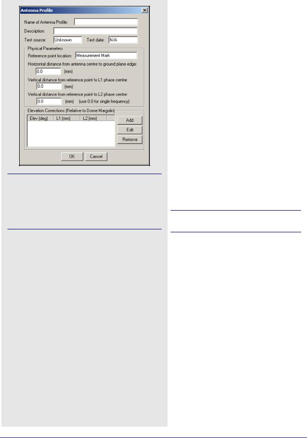
You can specify each antenna profile’s origin. If the antenna has multiple origins, then create a new profile for each one. Ensure that the final overall vertical antenna height is from the monument to the L1 phase centre. Refer to http://www.novatel.com/products/ waypoint_faqs.htm for more information.
How to create an antenna profile
1.Once you have the antenna characteristics, go to
Settings | Coordinate.
2.Press the Define button next to the antenna profile name under the Use advanced method option in the
Antenna Height box.
3.Select Add Empty, enter a name and the characteristics.
4.Press OK.
How to create an antenna profile with correction values from another antenna
1.Click the Define button under the Coordinate Settings window for the master or remote.
2.Select the model to copy from in the List of Antennas and click Add From. The vertical distance values may need to be modified and the horizontal distance may need to be inserted.
3.Be sure that the relationship between the L1 and L2 vertical offset is unchanged.
For features and static sessions, GrafNav lets you select the antenna model and height. It also allows you to enter the height measurements of the antennas long as a proper antenna model is being used. When using this option, ensure that the correct antenna height is entered and prepare to be required to edit the antenna information after a new project is created.
The antenna models are created from data acquired from NGS, and cannot use the measuring mark on the antenna as the origin. This adds an error of several centimeters to the antenna height. Check each antenna model before using it and ensure that the final overall vertical antenna height is from the monument to the L1 phase centre. The greyed Vertical antenna height field under Settings | Coordinate, for either the master or remote, shows this value. It is better to create your own profile if you have the following knowledge about the antenna characteristics:
•Vertical offset from the measurement mark to the L1 phase center
•Vertical offset from measurement mark to L2 phase center
Existing antenna profiles can be used for difference between L1 and L2 offsets.
•Horizontal radius of antenna from measurement mark. Used only for slant measurements
•Elevation-based antenna errors (optional)
Once you know these characteristics, follow the steps in the shaded box to create an antenna profile.
An antenna height model can also be created with correction values from another antenna. To do this, follow the steps in the shaded box.
See Appendix A on Page 291 for a diagram of different methods for making antenna measurements.
58 |
GrafNav / GrafNet 8.10 User Guide Rev 4 |
GrafNav |
Chapter 2 |
|
|
|
|
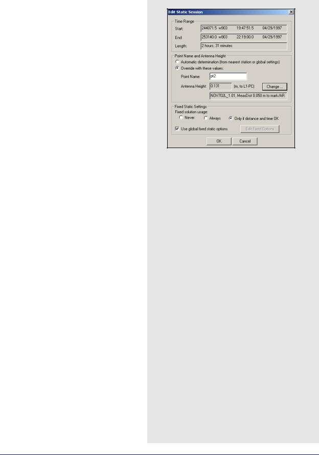
Edit Static Sessions
Select a static baseline from the Object Menu and click the Edit button to display the Edit Static Session window. The options in this window allow you to change station names, antenna heights and processing options for the static session.
Time Range
Displays information regarding the static session.
Start/End
Displays GPS seconds, GPS week number, GMT time and date (mm/dd/yyyy) for the beginning/end of the static session.
Length
Displays the difference between the start and end time.
Point Name and Antenna Height
Displays information regarding the observed point’s name and antenna height.
Automatic determination
Applies the antenna height and point name from the nearest station, if one exists within session. If not, then it uses the global remote antenna height and a station name of STATIC_???.
Override with these values
Allows you to manually enter the parameters that are listed in the shaded box.
Fixed static settings
Customizes the conditions and settings for the use of a fixed static solution.
Fixed solution usage
Gives you a choice of settings for the use of a fixed solution. The settings for this option are in the shaded box.
Use global fixed static options
Enable this feature to use the options under
Settings | Individual | Fixed Solution for the static session. Otherwise, click on the Edit Fixed Options button to customize the options for this session.
Override values
Point Name
Allows you change the station’s name.
Antenna Height
If this value is known. enter the antenna height, especially if a static session is being processed in GrafNav. To select an antenna model, click the Change… button.
Fixed solution usage settings
Never
Float solution are used for the static sessions.
Always
Fixed integer solution are attempted for the static sessions.
Only if distance and time OK
Fixed integer solution are attempted if the baseline distance and session length are within the constraints which are found under Settings | Individual | Advanced. Otherwise, a float solution is used.
GrafNav / GrafNet 8.10 User Guide Rev 4 |
59 |

Chapter 2 |
GrafNav |
|
|
How to view ASCII files
1.Select View | ASCII File(s).
2.Highlight the file to view and click
Open.
3.Right-click the file to view additional features. This lets you change the font or copy selected regions for pasting into other applications.
2.4.8 ASCII File (s)
The View ASCII File(s) option allows you to view any of the ASCII files generated by the software. Examples of these files include the following:
•Epoch Solutions (FWD, REV and CMB)
•Message Logs (FML and RML)
•Static Summaries (FSS and RSS)
•Station Files (STA)
•Ephemeris Files (EPP)
•Configuration Files (CFG).
2.4.9 Raw GPS
This option is also available under File | GPB Utilities | View Raw GPS Data, or through a separate utility called GPB Viewer. This option lets you view and edit binary GPS data in Waypoint’s receiver-independent GPB format. See Chapter 8 on Page 221 for more information.
2.4.10 Current CFG File
This option lets you view the Configuration File (CFG) of the current project. The CFG file is simply an ASCII file containing all of the processing options and user commands for the project. Definitions of all the commands shown in this window are available in Appendix A.
60 |
GrafNav / GrafNet 8.10 User Guide Rev 4 |