


Instruction Set Summary
3.5 FLOATING-POINT COMPUTATIONAL ACCURACY
Representing a real number in a binary format of finite precision is problematic. If the number cannot be represented exactly, a round-off error occurs. Furthermore, when two of these inexact numbers are used in a calculation, the result becomes even more inexact. The
IEEE 754 standard defines the error bounds for calculating binary floating-point values so that the result obtained by any conforming device can be predicted exactly for a particular precision and rounding mode. The error bound defined by the IEEE 754 standard is one-half unit in the last place of the destination data format in the RN mode, and one unit in last place in the other rounding modes. The operation’s data format must have the same input values, rounding mode, and precision. The standard also specifies the maximum allowable error that can be introduced during a calculation and the manner in which rounding of the result is performed.
The singleand double-precision formats provide emulation for devices that only support those precisions. The execution speed of all instructions is the same whether using singleor double-precision rounding. When using these two data formats, the FPU produces the same results as any other device that conforms to the IEEE standard but does not support extended precision. The results are the same when performing the same operation in extended precision and storing the results in singleor double-precision format.
The FPU performs all floating-point internal operations in extended-precision. It supports mixed-mode arithmetic by converting singleand double-precision operands to extendedprecision values before performing the specified operation. The FPU converts all memory data formats to the extended-precision data format and stores the value in a floating-point register or uses it as the source operand for an arithmetic operation. The FPU also converts extended-precision data formats in a floating-point data register to any data format and either stores it in a memory destination or in an integer data register.
Additionally if the external operand is a denormalized number, the number is normalized before an operation is performed. However, an external denormalized number moved into a
floating-point data register is stored as a denormalized number. The number is first normalized and then denormalized before it is stored in the designated floating-point data register. This method simplifies the handling of all other data formats and types.
If an external operand is an unnormalized number, the number is normalized before it is used in an arithmetic operation. If the external operand is an unnormalized zero (i.e., with a mantissa of all zeros), the number is converted to a normalized zero before the specified operation is performed. The regular use of unnormalized inputs not only defeats the purpose of the IEEE 754 standard, but also can produce gross inaccuracies in the results.
MOTOROLA |
M68000 FAMILY PROGRAMMER’S REFERENCE MANUAL |
3-23 |

Instruction Set Summary
3.5.1 Intermediate Result
All FPU calculations use an intermediate result. When the FPU performs any operation, the calculation is carried out using extended-precision inputs, and the intermediate result is calculated as if to produce infinite precision. After the calculation is complete, the intermediate result is rounded to the selected precision and stored in the destination.
Figure 3-1 illustrates the intermediate result format. The intermediate result’s exponent for some dyadic operations (i.e., multiply and divide) can easily overflow or underflow the 15bit exponent of the designation floating-point register. To simplify the overflow and underflow detection, intermediate results in the FPU maintain a 16-bit (17 bits for the MC68881 and MC68882), twos complement, integer exponent. Detection of an overflow or underflow intermediate result always converts the 16-bit exponent into a 15-bit biased exponent before being stored in a floating-point data register. The FPU internally maintains the 67-bit mantissa for rounding purposes. The mantissa is always rounded to 64 bits (or less, depending on the selected rounding precision) before it is stored in a floating-point data register.
.
|
|
|
|
|
|
|
|
|
|
|
|
16-BIT EXPONENT |
|
|
|
63-BIT MANTISSA |
|
||||||
|
|
|
|
|
|
|
|
|
|
|
|
|
|
|
|
LSB OF FRACTION |
|
|
|
|
|
||
|
|
|
|
|
|
|
|
|
|||
|
|
|
|
|
|
|
|
|
|||
|
|
|
INTEGER BIT |
GUARD BIT |
|
|
|
|
|||
|
|
|
|
|
|
|
|||||
|
|
|
ROUND BIT |
|
|
|
|
|
|
|
|
|
|
|
OVERFLOW BIT |
|
|
|
|||||
|
|
|
|
|
|
||||||
|
|
|
|
||||||||
|
|
|
STICKY BIT |
|
|
|
|
|
|
|
|
|
|
|
|
|
|
||||||
|
|
|
|
|
|
||||||
Figure 3-1. Intermediate Result Format
If the destination is a floating-point data register, the result is in the extended-precision format and is rounded to the precision specified by the FPSR PREC bits before being stored. All mantissa bits beyond the selected precision are zero. If the singleor double-precision mode is selected, the exponent value is in the correct range even if it is stored in extendedprecision format. If the destination is a memory location, the FPSR PREC bits are ignored.
In this case, a number in the extended-precision format is taken from the source floatingpoint data register, rounded to the destination format precision, and then written to memory.
Depending on the selected rounding mode or destination data format in effect, the location of the least significant bit of the mantissa and the locations of the guard, round, and sticky bits in the 67-bit intermediate result mantissa varies. The guard and round bits are always calculated exactly. The sticky bit is used to create the illusion of an infinitely wide intermediate result. As the arrow illustrates in Figure 3-1, the sticky bit is the logical OR of all the bits in the infinitely precise result to the right of the round bit. During the calculation stage of an arithmetic operation, any non-zero bits generated that are to the right of the round bit set the sticky bit to one. Because of the sticky bit, the rounded intermediate result for all required IEEE arithmetic operations in the RN mode is in error by no more than one half unit in the last place.
3-24 |
M68000 FAMILY PROGRAMMER’S REFERENCE MANUAL |
MOTOROLA |

Instruction Set Summary
3.5.2 Rounding the Result
The FPU supports the four rounding modes specified by the IEEE 754 standard. These modes are round to nearest (RN), round toward zero (RZ), round toward plus infinity (RP), and round toward minus infinity (RM). The RM and RP rounding modes are often referred to as "directed rounding modes" and are useful in interval arithmetic. Rounding is accomplished through the intermediate result. Single-precision results are rounded to a 24bit boundary; double-precision results are rounded to a 53-bit boundary; and extendedprecision results are rounded to a 64-bit boundary. Table 3-21 lists the encodings for the FPCR that denote the rounding and precision modes.
Table 3-21. FPCR Encodings
Rounding Mode |
Encoding |
Rounding Precision |
||
(RND Field) |
(PREC Field) |
|||
|
|
|||
|
|
|
|
|
To Nearest (RN) |
0 |
0 |
Extend (X) |
|
|
|
|
|
|
To Zero (RZ) |
0 |
1 |
Single (S) |
|
|
|
|
|
|
To Minus Infinity (RM) |
1 |
0 |
Double (D) |
|
|
|
|
|
|
To Plus Infinity (RP) |
1 |
1 |
Undefined |
|
|
|
|
|
|
Rounding the intermediate result’s mantissa to the specified precision and checking the 16bit intermediate exponent to ensure that it is within the representable range of the selected rounding precision accomplishes range control. Range control is a method used to assure correct emulation of a device that only supports singleor doubleprecision arithmetic. If the intermediate result’s exponent exceeds the range of the selected precision, the exponent value appropriate for an underflow or overflow is stored as the result in the 16-bit extendedprecision format exponent. For example, if the data format and rounding mode is single precision RM and the result of an arithmetic operation overflows the magnitude of the singleprecision format, the largest normalized single-precision value is stored as an extendedprecision number in the destination floating-point data register (i.e., an unbiased 15-bit exponent of $00FF and a mantissa of $FFFFFF0000000000). If an infinity is the appropriate result for an underflow or overflow, the infinity value for the destination data format is stored as the result (i.e., an exponent with the maximum value and a mantissa of zero).
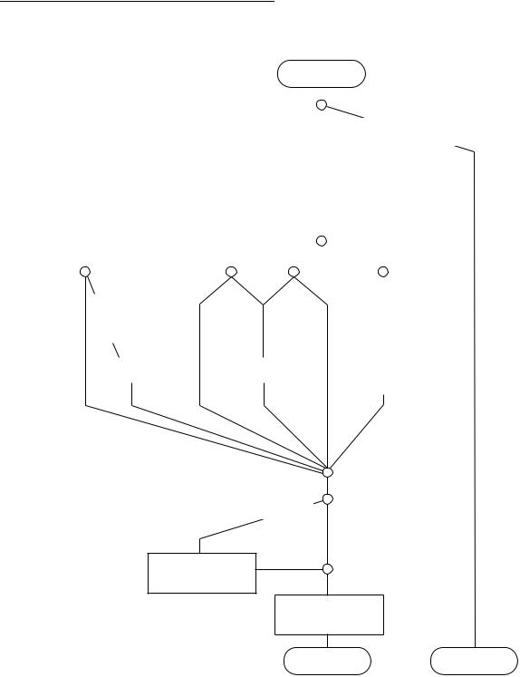
Figure 3-2 illustrates the algorithm that the FPU uses to round an intermediate result to the selected rounding precision and destination data format. If the destination is a floating-point register, either the selected rounding precision specified by the FPCR PREC status byte or by the instruction itself determines the rounding boundary. For example, FSADD and FDADD specify singleand double-precision rounding regardless of the precision specified in the FPCR PREC status byte. If the destination is external memory or an integer data register, the destination data format determines the rounding boundary. If the rounded result of an operation is not exact, then the INEX2 bit is set in the FPSR EXC status byte.
MOTOROLA |
M68000 FAMILY PROGRAMMER’S REFERENCE MANUAL |
3-25 |
Instruction Set Summary
.
|
|
|
|
|
|
|
|
|
|
ENTRY |
||||||||
|
|
|
|
|
|
|
|
|
|
|
|
|
|
|
|
|
|
|
|
|
|
|
|
|
|
|
|
|
|
|
|
|
|
|
|
|
|
|
|
|
|
|
|
|
|
|
|
|
|
|
|
|
|
|
||
|
|
|
|
|
|
|
|
|
|
|
|
|
|
|
|
|
||
|
|
|
|
|
|
|
|
|
|
|
|
|
GUARD, ROUND, |
|
||||
|
|
|
|
|
|
|
|
|
|
|
|
|
AND STICKY BITS = 0 |
|
||||
|
|
|
|
|
|
|
|
|
|
|
|
|
|
|
|
|
|
|
|
|
|
|
|
|
|
|
|
|
|
|
|
|
|
|
|
|
|
|
|
|
|
|
|
|
|
|
|
INEX2 1 |
|
|
|
|
|
|||
|
|
|
|
|
|
|
|
|
|
|
|
|
|
|
|
|
|
|
|
|
|
|
|
|
|
|
|
|
|
|
|
|
|
|
|
|
|
|
|
|
|
|
|
|
|
SELECT ROUNDING MODE |
|
|
|
|
|
|||||
|
|
|
|
|
|
|
|
|
|
|
|
|
|
|
|
|
|
|
|
|
|
|
|
|
|
|
|
|
|
|
|
|
|
|
|
||
|
|
|
|
|
|
|
|
|
|
|
|
|
|
|
||||
RN |
|
|
|
RM |
|
|
|
RP |
|
|
|
RZ |
|
|
|
|
||
|
|
|
|
|
|
|
|
|
|
|||||||||
|
|
|
|
|
|
|
|
|||||||||||
|
GUARD AND LSB = 1, |
POS |
|
NEG POS |
NEG |
|
||||||||||||
|
|
|
|
|
|
|
|
|
|
|
|
|
|
|
|
|||
|
ROUND AND STICKY = 0 |
INTERMEDIATE INTERMEDIATE |
|
|
|
|
||||||||||||
|
|
OR |
|
|||||||||||||||
|
|
GUARD = 1 |
RESULT |
|
RESULT |
|
||||||||||||
|
ROUND OR STICKY = 1 |
|
|
|
|
|
|
|
|
|
|
|
|
|
|
|
||
|
|
|
|
|
|
|
|
|
|
|
|
|
|
|
|
|
EXACT RESULT |
|
|
|
|
|
|
|
|
|
|
|
|
|
|
|
|
|
|
|
|
|
|
ADD 1 TO |
|
|
|
ADD 1 TO |
|
|
|
|
GUARD, ROUND, |
|
|
|
||||
|
|
LSB |
|
|
|
|
LSB |
|
|
|
|
AND STICKY ARE |
|
|
|
|||
|
|
|
|
|
|
|
|
|
|
|
|
|
CHOPPED |
|
|
|
||
OVERFLOW = 1
SHIFT MANTISSA
RIGHT 1 BIT,
ADD 1 TO EXPONENT
GUARD 0
ROUND 0
STICKY 0
EXIT |
EXIT |
Figure 3-2. Rounding Algorithm Flowchart
The three additional bits beyond the extended-precision format, the difference between the intermediate result’s 67-bit mantissa and the storing result’s 64-bit mantissa, allow the FPU to perform all calculations as though it were performing calculations using a float engine with infinite bit prec The result is always correct for the specified destination’s data format before performing rounding (unless an overflow or underflow error occurs). The specified rounding operation then produces a number that is as close as possible to the infinitely precise
3-26 |
M68000 FAMILY PROGRAMMER’S REFERENCE MANUAL |
MOTOROLA |