

Universal Serial Bus Specification Revision 1.1
Series “A” receptacle mates with a Series “A” plug. Electrically, Series “A” receptacles function as outputs from host systems and/or hubs.
Series “A” plug mates with a Series “A” receptacle. The Series “A” plug always is oriented towards the host system.
Series “B” receptacle mates with a Series “B” plug (male). Electrically, Series “B” receptacles function as inputs to hubs or devices.
Series “B” plug mates with a Series “B” receptacle. The Series “B” plug is always oriented towards the USB hub or device.
6.3Cable
USB cable consists of four conductors, two power conductors and two signal conductors.
Full-speed cable consists of a signaling twisted pair, VBUS, GND, and an overall shield. Full-speed cable must be marked to indicate suitability for USB usage (see Section 6.6.2). Full-speed cable may be used with either Low-speed or Full-speed devices. When Full-speed cable is used with Low-speed devices, the cable must meet all Low-speed requirements.
Low-speed cable does not require twisted signaling conductors or the overall shield.
6.4 Cable Assembly
This specification describes three USB cable assemblies. Detachable cable, Full-speed captive cable, and Low-speed captive cable.
The color used for the cable assembly is vendor specific, recommended colors are White, Grey, or Black.
6.4.1 Detachable Cable Assemblies
Full-speed devices can utilize the “B” connector. This allows the device to have a detachable USB cable. This eliminates the need to build the device with a hardwired cable and minimizes end user problems if cable replacement is necessary.
Devices utilizing the “B” connector must be designed to work with worst case maximum length detachable cable. Detachable cable assemblies may be used only on Full-speed devices. Using a Full-speed detachable cable on a Low-speed device may exceed the maximum Low-speed cable length.
Figure 6-2 illustrates a detachable cable assembly.
74
Universal Serial Bus Specification Revision 1.1
8 |
7 |
6 |
5 |
4 |
3 |
2 |
1 |
IMPORTANT NOTICE: All detachable cable assemblies must be Full Speed.
H |
H |
|
A |
B |
G |
A |
G |
|
B |
|
|
Overmolded Series "A" Plug |
Overmolded Series "B" Plug |
|
(Always upstream towards the "host" system.) |
(Always downstream towards the USB Device.) |
C
 C
C
F |
F |
|
|
|
|
|
C |
C |
|
|
|
|
|
|
|
|
|
|
|
Detail C - C |
|
||
Detail A - A |
Detail B - B |
|
(Typical USB Shielded Cable) |
|
||||||
|
|
|
|
E |
||||||
E |
|
|
|
(Series "B" Plug) |
|
|
|
|
||
(Series "A" Plug) |
|
Polyvinyl Chloride (PVC) Jacket |
|
|||||||
|
|
|
|
|
|
|
> 65% Tinned Copper Braided Shield |
|||
|
15.7 |
|
10.5 |
11.5 |
|
Aluminum Metallized Polyester Inner Shield |
||||
|
7.5 |
|
|
|||||||
|
|
|
|
|
|
|
28 AWG STC Drain Wire |
|
||
|
|
|
|
2 |
1 |
|
|
|
|
|
1 |
2 |
3 |
4 |
|
|
|
|
|
|
|
|
|
|
|
3 |
4 |
|
|
|
|
|
D |
|
|
|
|
|
|
|
|
|
D |
|
|
|
|
|
|
|
Red (VB U S) |
Green (D +) |
|
|
|
|
|
12.0 |
12.0 |
|
Black (Ground) |
White (D -) |
|
||
C |
|
|
27.0 |
32.0 |
|
|
|
|
|
C |
|
|
|
|
|
All dimensions are in millimeters ( m m ) |
|||||
|
|
|
|
|
|
|||||
|
|
|
|
|
|
unless otherwise noted. |
|
|
||
|
|
|
|
|
|
Dimensions are TYPICAL and are for |
||||
|
|
|
|
|
|
general reference purposes only. |
|
|||
B |
|
|
9.0 |
|
|
|
|
|
|
B |
|
|
|
9.0 |
|
|
|
|
|
||
|
|
|
|
|
|
|
|
|
|
|
|
|
|
Optional Molded |
|
|
|
|
|
|
|
|
|
|
Strain Relief |
|
|
Series "A" Plug to Series "B" Plug |
||||
|
|
|
|
|
|
|
||||
|
|
|
|
|
|
|
|
USB Detachable |
|
|
A |
|
|
|
|
|
|
|
Cable Assembly |
A |
|
|
|
|
|
|
|
|
SIZE |
DATE |
DRAWING NUMBER |
REV |
|
|
|
|
|
|
|
A |
2/98 |
N/A |
C |
|
|
|
|
|
|
|
SCALE: |
N/A |
SHEET |
1 of 1 |
8 |
|
|
7 |
6 |
5 |
4 |
3 |
|
2 |
1 |
Figure 6-2. USB Detachable Cable Assembly
75
Universal Serial Bus Specification Revision 1.1
Detachable Cables must meet the following electrical requirements:
The cable must be terminated on one end with an overmolded Series “A” plug and the opposite end is terminated with an overmolded Series “B” plug.
The cable must be rated for Full-speed.
The cable impedance must match the impedance of the Full-speed drivers. The drivers are characterized to drive specific cable impedance. Refer to Section 7.1.1 for details.
The maximum allowable cable length is determined by signal pair attenuation. Refer to Section 7.1.17 for details.
The maximum allowable cable length determined by the cable propagation delay. The USB utilizes an unterminated transmission scheme. Exceeding this limit will cause signaling reflections to interfere with data transmission. Refer to Section 7.1.14 for details.
Differences in propagation delay between the two signal conductors must be minimized. Refer to Chapter 7.1.3 for details.
The GND lead provides a common ground reference between the upstream and downstream ports. The maximum cable length is limited by the voltage drop across the GND lead. Refer to Section 7.2.2 for details. The minimum acceptable wire gauge is calculated assuming the attached device is high power
The VBUS lead provides power to the connected device. For detachable cables, the VBUS requirement is the same as the GND lead.
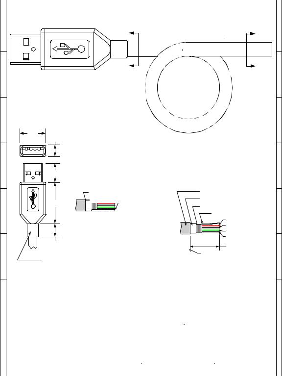
6.4.2Full-speed Captive Cable Assemblies
Full-speed captive cable assemblies may be used with either Full-speed or Low-speed devices. Assemblies are considered captive if they are provided with a vendor-specific disconnect means. When using a Fullspeed captive cable on a Low-speed device the cable must meet all Low-speed requirements.
Figure 6-3 illustrates a Full-speed cable assembly.
76
Universal Serial Bus Specification Revision 1.1
8 |
7 |
6 |
5 |
4 |
3 |
2 |
1 |
H |
A |
B |
H |
|
|
|
|
|
A |
B |
G |
|
|
Overmolded Series "A" Plug |
G |
|
|
|
|
|
(Always upstream towards the "host" system.) |
|
|||
Detail A - A |
|
|||
(Series "A" Plug) |
|
|||
F |
|
|
|
F |
|
15.7 |
Cut End |
||
|
|
|
7.5 |
|
|
|
|
(Always downstream towards the USB Device.) |
|
1 |
2 |
3 |
4 |
|
E |
|
|
Detail B - B (Typical Terminations) |
E |
|
|
|
12.0 |
|
|
Blunt Cut Termination |
Prepared Termination |
|
Polyvinyl Chloride (PVC) |
Polyvinyl Chloride (PVC) Jacket |
27.0 |
Jacket |
> 65% Tinned Copper Braided |
Blunt Cut Termination |
Shield |
|
|
|
|
|
(Length Dimension Point) |
Metallized Mylar Inner Shield |
|
|
D |
|
28 AWG STC Drain Wire |
D |
|
|
Red (VB U S) |
|
|
|
Black (Ground) |
|
|
|
Green (D +) |
|
|
|
White (D -) |
|
|
9.0 |
User Specified |
|
|
|
|
|
|
|
Length Dimension Point |
|
C |
Optional Molded |
|
C |
|
Strain Relief |
|
|
B All dimensions are in |
millimeters |
(m m ) |
|
|
|
|
|
|
|
|
|
|
|
|
B |
|||
|
unless otherwise note. |
|
|
|
|
|
|
|
|
|
|
|
|
|
|
|
||
|
D i m e n s i o n s |
a r e T Y P I C A L an d ar e for |
|
|
|
|
|
|
|
|
|
|
|
|
|
|||
|
general reference purposes only. |
|
|
|
|
|
Series "A" Plug to Cut End |
|
||||||||||
|
|
|
|
|
|
|
|
|
|
|
|
|
|
|
|
|
|
|
|
|
|
|
|
|
|
|
|
|
USB Full Speed |
|
|
|
|
||||
A |
|
|
|
|
|
Hardwired Cable Assembly |
A |
|||||||||||
|
|
|
|
|
|
|
|
SIZE |
|
DATE |
DRAWING NUMBER |
|
REV |
|
|
|||
|
|
|
|
|
|
|
|
|
|
|
||||||||
|
|
|
|
|
|
|
|
|
|
2/98 |
|
N/A |
|
|
|
|
||
|
|
|
|
|
|
|
|
A |
|
|
C |
|||||||
|
|
|
|
|
|
|
|
SCALE: N/A |
|
SHEET |
1 of 1 |
|
|
|||||
8 |
|
7 |
6 |
5 |
4 |
|
3 |
|
|
|
2 |
|
|
1 |
|
|
|
|
Figure 6-3. USB Full-speed Hardwired Cable Assembly
77