СУБД Oracle / Литература / PowerDesigner 9 / GeneralFeatures
.pdf&KDSWHU 0RGHO *UDSKLFV
6HWWLQJ OLQH GLVSRVLWLRQ
|
You can set the horizontal or vertical disposition of any line in the model. A |
|
change in disposition straightens lines and, where applicable, aligns their |
|
attach points (for example, aligning reference attach points). |
Horizontal |
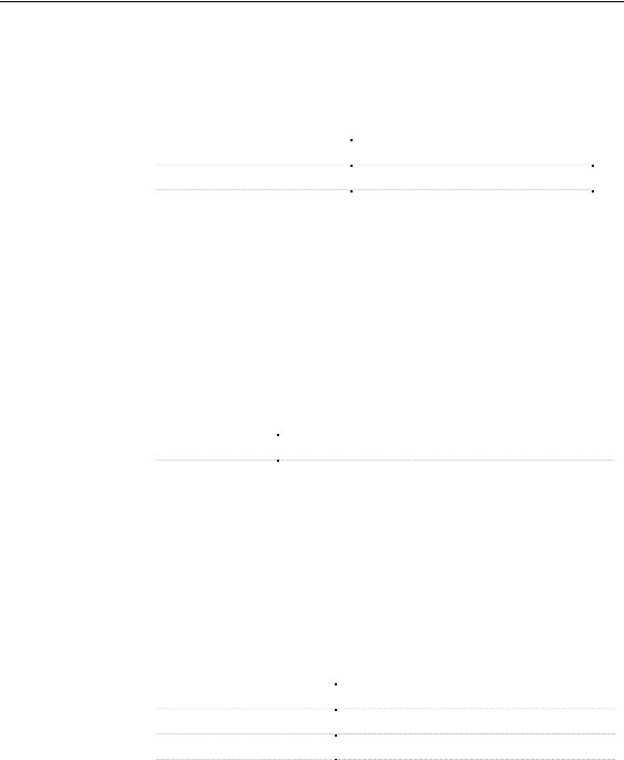
This model shows a reference before setting horizontal disposition. |
disposition |
|
This is the same model after setting horizontal disposition.
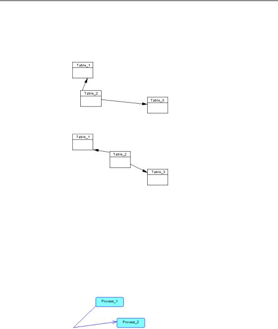
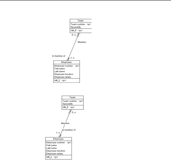
Vertical disposition This model shows a reference before setting vertical disposition.
This is the same model after setting vertical disposition.
ϖ7R VHW OLQH GLVSRVLWLRQ
1 Select one or more lines.
2Select Symbol→Disposition→Horizontal.
RU
Select Symbol→Disposition→Vertical.
General Features Guide |
|
&KDSWHU 0RGHO *UDSKLFV
This model shows the same flow after arranging connectors:
ϖ7R DUUDQJH FRQQHFWRUV
1 Select one or more lines.
2 Select Symbol→Disposition→Arrange Connectors.
$UUDQJLQJ DWWDFK SRLQWV
Arranging attach points moves the endpoints of a line to the center of objects on either end of a line.
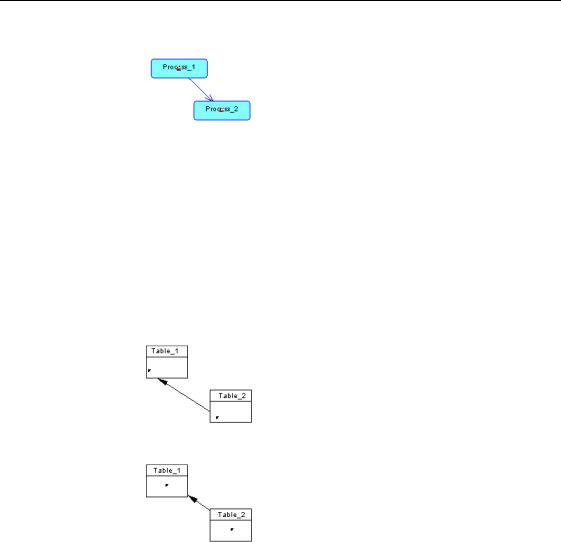
This model shows a reference before arranging attach points:
This model shows the same reference after arranging attach points:
ϖ7R DUUDQJH DWWDFK SRLQWV
1 Select one or more lines.
2 Select Symbol→Disposition→Arrange Attach Points.
$UUDQJLQJ DWWDFKHG WH[W
Arranging attached text moves back to its default place the text of a link you have moved.
General Features Guide |
|
&KDSWHU 0RGHO *UDSKLFV
2YHUODSSLQJ V\PEROV
When you insert symbols in a model, they appear in overlapping layers, as follows:
♦A new symbol that can contain text appears in front of all other symbols
♦A new line appears behind all other symbols
You can use the following commands to change the layer of a selected symbol.
6XEPHQX LWHP |
'HVFULSWLRQ |
|
Bring to front |
Selected symbol appears in front of all other symbols |
|
Send to back |
Selected symbol appears behind all other symbols |
|
Bring forward |
Selected symbol moves forward one layer |
|
Send backward |
Selected symbol moves backward one layer |
|
|
|
ϖ7R RUGHU RYHUODSSLQJ V\PEROV
1 Select a symbol.
2 Select Symbol→Order→RUGHU LWHP.
)LQGLQJ D V\PERO LQ WKH GLDJUDP IURP DQ REMHFWV OLVW
You can locate any object in a diagram from an object list using the
PowerDesigner Find feature.
ϖ 7R ILQG D V\PERO LQ WKH GLDJUDP IURP DQ REMHFWV OLVW
1Select Model→/LVW RI submenu.
2Select an object in the list.
An arrow appears at the beginning of the line.
3Click the Find Symbol in Diagram tool.
The symbol is selected and centered in the diagram window. To see the symbol, you have to move the list dialog box.
General Features Guide |
|

&KDSWHU 0RGHO *UDSKLFV
,QVHUWLQJ JUDSKLFV
You can improve the visual appeal of your models by adding shapes and lines. You can use graphic elements to surround parts of a model, for example, to distinguish domains of activity.
'UDZLQJ VKDSHV
ϖ7R GUDZ D UHFWDQJOH
1 Click the Rectangle tool.
2 Drag and drop the far corner of a rectangle from any point in your model.
ϖ7R GUDZ D VTXDUH
1 Click the Rectangle tool.
2 Press CTRL while you drag and drop the far corner of a square from any point in your model.
ϖ7R GUDZ DQ RYDO
1 Click the Oval tool.
2 Drag and drop the far end of an oval from any point in your model.
ϖ7R GUDZ D FLUFOH
1 Click the Oval tool.
2 Press CTRL while you drag and drop the far end of the circle from any point in your model.
ϖ7R GUDZ D URXQGHG UHFWDQJOH
1 Click the Rounded Rectangle tool.
2 Drag and drop the far corner of a rounded rectangle from any point in your model.
General Features Guide |
|
&KDSWHU 0RGHO *UDSKLFV
0RGLI\LQJ WKH W\SH RI FRUQHUV
After creating the polyline, you can modify the type of corner by right-clicking and selecting Format→Line Style and selecting a type in the Corners box. You can also define a default style for corners in the display preferences of free symbols.
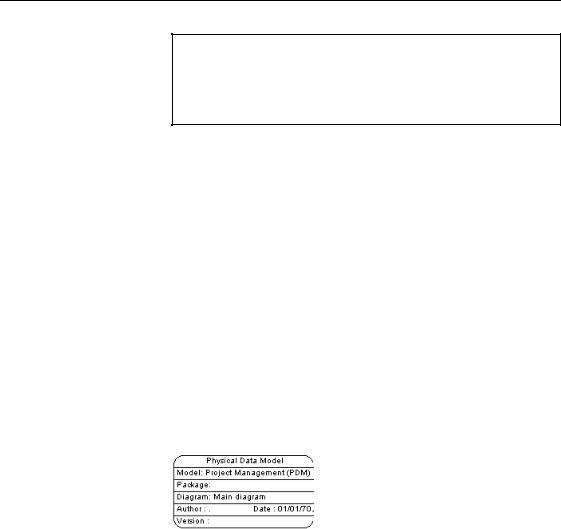
,QVHUWLQJ D WLWOH ER[
A title box displays essential information about the diagram such as: the model and the package to which the diagram belongs, the name of the diagram itself, the author and version of the model and the date of modification. This information is retrieved from the model properties.
For more information about model properties, see section Model Properties in chapter Managing models.
The title box automatically takes into account any changes you make to model properties.
ϖ7R LQVHUW D WLWOH ER[
1 Select the Title tool.
2 Click in an empty space in the diagram window. The title box symbol appears.
General Features Guide |
|