

Диплом ИМЭ, ССК / Диплом / diplom / Приложения / HANDBOOK_DOD-Systems-Engineering-Guide-2001-01
.pdfChapter 7 |
|
Verification |
|
|
From: Synthesis |
|
|
|
Physical Verification |
|
|
|
Select |
|
|
|
Verification Approach |
|
|
Define, Inspection, Analysis, |
Define |
Establish Verification |
|
Demo, or Test Requirements |
Verification Procedures |
Environment |
|
|
Conduct |
• Requirements Vaseline |
|
|
Verification Evaluation |
• Functional Architecture |
|
Verify Architectural |
Verify |
Verify Satisfaction |
|
Completeness |
Functional and |
of Constraints |
|
|
Performance Measures |
|
|
|
Identify |
To: |
|
|
Variance and Conflicts |
||
|
• Requirements Analysis |
||
|
|
||
Verified Physcial |
|
• Synthesis |
|
|
|
||
Architectures of |
Verified |
|
|
Life Cycle Products/Processes |
To: Control |
||
Physical Architecture |
|||
|
|
||
Verified |
|
Establish Specifications and |
|
System Architecture |
|
Configuration Baselines |
|
To: Control |
|
Develop Product |
|
|
|
Breakdown Structure(s) |
|
|
|
Adapted from IEEE 1220 |
Figure 7-2. Verification Tasks
satisfied, and independent analysis and tests verify the system’s operational effectiveness and suitability. DoD T&E traditionally and by directive is categorized as:
•Developmental T&E which focuses primarily on technical achievement,
•Operational T&E which focuses on operational effectiveness and suitability and includes Early Operational Assessments (EOA), Operational Assessment (OA), Initial Operational Test and
Evaluation (IOT&E), and Follow-On Operational Test and Evaluation (FOT&E), and
•Live Fire T&E which provides assessment of the vulnerability and lethality of a system by subjecting it to real conditions comparable to the required mission.
T&E
The program office plans and manages the test effort to ensure testing is timely, efficient,
67
Systems Engineering Fundamentals |
Chapter 7 |
comprehensive and complete—and that test results are converted into system improvements. Test planning will determine the effectiveness of the verification process. Like all systems engineering planning activities, careful attention to test planning can reduce program risk. The key test planning document is the Test and Evaluation Master Plan (TEMP). This document lays out the objectives, schedule, and resources reflecting program office and operational test organization planning decisions. To ensure integration of this effort, the program office organizes a Test Planning Work Group (TPWG) or Test Working Level IPT (WIPT) to coordinate the test planning effort.
Test Planning Work Group/Test WIPT
The TPWG/Test WIPT is intended to facilitate the integration of test requirements and activities through close coordination between the members who represent the material developer, designer community, logistic community, user, operational tester, and other stakeholders in the system development. The team outlines test needs based on system requirements, directs test design, determines needed analyses for each test, identifies potential users of test results, and provides rapid dissemination of test and evaluation results.
Test and Evaluation Master Plan (TEMP)
The Test and Evaluation Master Plan is a mandatory document prepared by the program office. The operational test organization reviews it and provides the operational test planning for inclusion. The TEMP is then negotiated between the program office and operational test organization. After differences are resolved, it is approved at appropriate high levels in the stakeholder organizations. After approval it becomes binding on managers and designers (similar to the binding nature of the Operational Requirements Document (ORD)).
The TEMP is a valuable Verification tool that provides an excellent template for technology, system, and major subsystem-level Verification planning. The TEMP includes a reaffirmation of the user requirements, and to an extent, an interpretation of what those requirements mean in various
operational scenarios. Part I of the required TEMP format is System Introduction, which provides the mission description, threat assessment, MOEs/ MOSs, a system description, and an identification of critical technical parameters. Part II, Integrated Test Program Summary, provides an integrated test program schedule and a description of the overall test management process. Part III, Developmental Test & Evaluation (DT&E) Outline, lays out an overview of DT&E efforts and a description of future DT&E. Part IV, Operational Test & Evaluation (OT&E) Outline, is provided by the operational test organization and includes an OT&E overview, critical operational issues, future OT&E description, and LFT&E description. Part V, Test
& Evaluation Resource Summary, identifies the necessary physical resources and activity responsibilities. This last part includes such items as test articles, test sites, test instrumentation, test support equipment, threat representation, test targets and other expendables, operational force test support, simulations, models, test-beds, special requirements, funding, and training.
Key Performance Parameters
Every system will have a set of KPPs that are the performance characteristics that must be achieved by the design solution. They flow from the operational requirements and the resulting derived MOEs. They can be identified by the user, the decision authority, or the operational tester. They are documented in the TEMP.
Developmental Test and Evaluation
The DT&E verifies that the design solution meets the system technical requirements and the system is prepared for successful OT&E. DT&E activities assess progress toward resolving critical operational issues, the validity of cost-performance tradeoff decisions, the mitigation of acquisition technical risk, and the achievement of system maturity.
DT&E efforts:
•Identify potential operational and technological capabilities and limitations of the alternative concepts and design options being pursued;
68
Chapter 7 |
|
|
|
|
|
|
|
|
|
|
|
|
|
|
|
|
|
|
|
|
|
|
Verification |
|||||||||
|
|
|
|
|
|
|
|
|
|
|
|
|
|
|
|
|
|
|
|
|
|
|
|
|
|
|
|
|
|
|
|
|
|
|
|
|
|
|
|
|
|
|
|
|
|
|
|
|
|
|
|
|
|
|
DT&E |
|
|
|
|||||||
|
|
|
|
|
|
|
|
|
|
|
|
|
|
|
|
|
|
|
|
|
|
|
|
|
|
|
|
|||||
|
|
|
|
|
|
|
|
|
|
|
|
|
|
|
|
|
|
|
|
|
|
|
– Engineering completeness |
|
|
|
||||||
|
|
|
|
|
|
|
|
|
|
|
|
|
|
|
|
|
|
|
|
|
|
|
– System performance |
|
|
|
||||||
|
|
|
|
|
|
|
|
|
|
|
|
|
|
|
DT&E |
|
– Validate specifications |
|
|
|
||||||||||||
|
|
|
|
|
|
|
|
|
|
|
|
|
|
|
|
|
|
|
|
|
|
|
– Technical compliance test |
|
|
|
||||||
|
|
|
Technology |
|
|
|
|
|
|
|
|
– Preferred tech |
|
– Qualification tests |
|
|
|
|||||||||||||||
|
|
|
Feasibility |
|
|
|
|
|
|
|
|
|
|
approach |
|
|
|
|
|
|
|
|
|
|
|
|||||||
|
|
|
|
|
|
|
|
|
|
|
– Technical risk |
|
|
|
|
|
|
|
|
|
|
|
||||||||||
|
|
|
Testing |
|
|
|
|
|
|
|
|
|
|
|
|
|
|
|
|
|
|
|
||||||||||
|
|
|
|
|
|
|
|
|
|
|
– Engineering |
|
|
|
DT&E |
|
|
|
||||||||||||||
|
|
|
|
|
|
|
|
|
|
|
|
|
|
|
|
|
|
|
design |
|
|
|
|
|
|
|||||||
|
|
|
|
|
|
|
|
|
|
|
|
|
|
|
|
|
|
|
solutions |
|
|
|
|
|
|
|
|
|
|
|
||
|
|
|
|
|
|
|
|
|
DT&E |
|
|
|
|
|
|
|
|
|
– Validates specifications |
|||||||||||||
|
|
|
|
|
|
|
|
|
|
|
|
|
|
|
|
|
|
|
|
|
||||||||||||
|
|
|
Technology |
|
|
|
|
|
|
|
|
|
|
|
|
|
|
– System performance |
||||||||||||||
|
|
|
|
|
|
|
|
|
Simulation |
|
|
|
|
|
||||||||||||||||||
|
|
|
|
|
|
|
|
|
|
|
|
|
|
|
|
|
|
|
|
|
|
|
|
– Modifications |
||||||||
|
|
|
|
|
|
|
|
|
|
|
|
|
|
|
|
|
|
|
|
|
|
|
|
|
|
|
– Product acceptance |
|||||
|
|
|
|
Studies and |
|
|
|
|
|
|
|
|
|
|
|
|
|
|
|
|
|
|
|
|
|
|
DT&E |
|||||
|
|
|
|
Analysis |
|
|
|
|
Requirements |
|
|
Production |
|
|
|
|
|
Production |
|
|||||||||||||
|
|
|
|
|
|
|
|
|
|
|
|
|
|
|
|
|
|
|
||||||||||||||
|
|
|
|
|
|
|
|
|
|
|
|
|
|
|
||||||||||||||||||
|
|
|
|
|
|
|
|
|
|
|
|
|
|
|
|
|
|
Design |
|
|
|
|
|
Design |
|
|
– Modifications |
|||||
|
|
|
|
|
Simulation |
|
|
|
|
|
Simulation |
|
|
|
|
|
|
|
|
|
|
|
|
|
|
|
|
|||||
|
|
|
|
|
|
|
|
|
|
|
|
|
|
|
|
|
|
|
|
|
|
|
|
|
|
– Alternatives |
||||||
|
|
|
|
|
|
|
|
|
|
|
|
|
|
|
|
|
|
|
|
|
|
|
|
|
|
|
|
|
||||
|
MS A |
|
MS B |
|
MS C |
|
|
|
|
|
|
|
|
|
|
|
||||||||||||||||
|
|
|
|
Concept and |
|
|
|
|
|
System |
|
|
|
|
Production |
|
|
|
|
|
|
|
|
Operations |
|
|||||||
|
|
|
|
Technology |
|
|
|
Development |
|
|
|
|
and |
|
|
|
|
|
|
|
|
and |
|
|||||||||
|
|
|
|
Development |
|
|
|
|
|
and |
|
|
|
|
Deployment |
|
|
|
|
|
|
|
|
Support |
|
|||||||
|
|
|
|
|
|
|
|
|
|
|
|
Demonstration |
|
|
|
|
|
|
|
|
|
|
|
|
|
|
|
|
|
|
||
|
|
|
|
|
|
|
|
|
|
|
|
|
|
|
|
|
|
|
|
|
|
|
|
|
|
|
|
|
|
|
|
|
|
|
|
|
|
|
|
|
|
|
|
|
|
|
|
|
|
|
|
|
|
|
|
|
|
|
|
|
|
|
|
|
|
Figure 7-3. DT&E During System Acquisition
•Support the identification of cost-performance tradeoffs by providing analyses of the capabilities and limitations of alternatives;
•Support the identification and description of design technical risks;
•Assess progress toward resolving Critical Operational Issues, mitigating acquisition technical risk, achieving manufacturing process requirements and system maturity;
•Assess validity of assumptions and analysis conclusions; and
•Provide data and analysis to certify the system ready for OT&E, live-fire testing and other required certifications.
Figure 7-3 highlights some of the more significant DT&E focus areas and where they fit in the acquisition life cycle.
Live Fire Test and Evaluation
LFT&E is performed on any Acquisition Category (ACAT) I or II level weapon system that includes features designed to provide protection to the system or its users in combat. It is conducted on a production configured article to provide information concerning potential user casualties, vulnerabilities, and lethality. It provides data that can establish the system’s susceptibility to attack and performance under realistic combat conditions.
Operational Test and Evaluation
OT&E programs are structured to determine the operational effectiveness and suitability of a system under realistic conditions, and to determine if the minimum acceptable operational performance requirements as specified in the ORD and reflected by the KPPs have been satisfied. OT&E uses threatrepresentative forces whenever possible, and employs typical users to operate and maintain the system or item under conditions simulating both combat stress and peacetime conditions. Operational tests will use production or production-
69
Systems Engineering Fundamentals |
|
|
|
|
|
|
|
|
|
|
|
|
|
|
|
|
|
|
Chapter 7 |
|||||||||||||||
|
|
|
|
|
|
|
|
|
|
|
|
|
|
|
|
|
|
|
|
|
|
|
|
|
|
|
|
|
|
|
|
|
|
|
|
|
|
|
|
|
|
|
|
|
|
|
|
|
|
|
|
|
|
|
|
|
|
||||||||||||
|
MS A |
MS B |
|
|
|
|
|
|
MS C |
|
|
|
|
|
|
|
|
|
|
|
||||||||||||||
|
|
Concept and |
|
|
|
|
|
|
System |
|
|
|
|
Production |
|
|
|
|
|
|
Operations |
|
||||||||||||
|
|
Technology |
|
|
|
|
Development |
|
|
|
|
|
and |
|
|
|
|
|
|
|
and |
|
||||||||||||
|
|
Development |
|
|
|
|
|
|
and |
|
|
|
|
Deployment |
|
|
|
|
|
|
Support |
|
||||||||||||
|
|
|
|
|
|
|
|
|
Demonstration |
|
|
|
|
|
|
|
|
|
|
|
|
|||||||||||||
|
|
|
|
|
|
|
|
|
|
|
|
|
|
|
|
|
|
|
|
|
|
|
|
|
|
|
|
|
|
|
|
|
|
|
|
|
|
|
|
|
|
|
|
|
|
|
|
|
|
|
|
|
|
|
|
|
|
|
|
|
|
|
|
|
|
|
– Validate |
||
|
|
|
|
|
|
|
|
|
|
|
|
|
|
|
|
|
|
|
|
|
|
|
|
|
|
|
|
|
|
|
|
Requirements |
||
|
|
Mission |
|
Integrated |
|
|
|
Simulation |
|
|
|
|
|
|
|
|
|
|
|
|
|
– Operational |
||||||||||||
|
|
|
|
|
|
|
|
|
|
|
IOT&E |
|
|
|
|
|||||||||||||||||||
|
|
Area |
|
Program |
|
|
|
|
|
|
|
|
|
|
|
|
|
|
|
|
|
utility |
||||||||||||
|
|
|
|
|
|
|
|
|
|
|
|
|
|
– Operational utility |
|
|
|
|
– Independent |
|||||||||||||||
|
|
Analysis |
|
Summary |
|
|
|
|
|
|
|
|
|
|
|
|
|
|
|
evaluation |
||||||||||||||
|
|
|
|
|
|
|
|
|
|
|
|
|
|
|
|
|
|
|
|
|
|
– Production validation |
|
|
|
|
|
|
|
|||||
|
|
|
|
|
|
|
|
|
|
|
|
|
|
|
|
|
|
|
|
|
|
– Independent assessment |
|
|
|
|
|
|
|
|||||
|
|
|
|
|
|
|
|
|
|
|
|
|
|
|
|
|
|
|
|
|
|
|
|
IOT&E |
||||||||||
|
|
|
|
|
|
|
|
|
|
|
|
|
|
|
|
|
|
|
|
|
|
|
|
|
|
|
|
|
|
|||||
|
|
|
|
|
Concept |
|
|
|
|
|
|
|
|
|
|
|
OA |
|
|
|
|
|
|
– Follow-on OT&E |
||||||||||
|
|
|
|
|
Studies |
|
|
|
|
|
|
|
|
|
|
|
|
|
|
|
|
|||||||||||||
|
|
|
|
|
|
|
|
|
|
|
|
|
|
|
|
|
|
|
|
|
|
|
|
– Operational utility |
||||||||||
|
|
|
|
|
|
|
|
|
|
|
|
|
|
|
|
|
|
|
|
|
|
|
|
|
|
|
|
|
– Tactics-doctrine |
|||||
|
|
|
|
|
|
|
|
|
|
|
|
|
|
|
|
|
|
|
|
|
|
|
|
|
|
|
|
|||||||
|
|
|
|
|
|
|
|
|
|
|
|
|
|
|
|
|
– Potential effectiveness |
|
|
|
|
|
personnel |
|||||||||||
|
|
|
|
|
|
|
|
|
|
|
|
|
|
|
|
|
– Suitability |
|
|
|
|
|
_ Interoperability |
|||||||||||
|
|
|
|
|
|
|
|
|
|
|
|
|
|
|
|
|
– Alternatives |
|
|
|
|
|
|
|
|
|
|
|
||||||
|
|
|
|
|
|
|
|
|
|
|
|
|
|
|
|
|
|
|
|
|
IOT&E |
|||||||||||||
|
|
|
|
|
|
|
|
|
|
|
|
|
|
|
|
|
– Independent evaluation |
|
|
|
|
|||||||||||||
|
|
|
|
|
|
|
|
|
|
|
|
|
|
|
|
|
– Milestone II decision information |
|
|
|
|
|
|
|
||||||||||
|
|
|
|
|
|
|
|
|
|
|
|
|
|
|
|
|
|
|
|
|
|
|
|
|
|
|
|
|
|
|
|
|||
|
|
|
|
|
|
|
|
|
|
|
|
|
|
|
EOA |
|
|
|
|
|
|
|
|
|
|
|
||||||||
|
|
|
|
|
|
|
|
|
– Operational aspects |
|
|
|
|
|
|
|
|
|
|
|
||||||||||||||
|
|
|
|
|
|
|
|
|
–Preferred alternatives |
|
|
|
|
|
|
|
|
|
|
|
||||||||||||||
|
|
|
|
|
|
|
|
|
|
|
|
|
|
|
|
|
|
|
|
|
|
|
|
|
|
|
|
|
|
|
|
|
|
|
|
|
|
|
|
|
EOA |
|
|
|
|
|
|
|
|
|
|
|
|
|
|
|
|
|
|
|
|
|
|
|
|
||||
|
|
|
|
|
|
|
|
|
|
|
|
|
|
|
|
|
|
|
|
|
|
|
|
|
|
|
|
|
|
|
|
|
|
|
Figure 7-4. OT&E During System Acquisition
representative articles for the operational tests that support the full-rate production decision. Live Fire Tests are usually performed during the operational testing period. Figure 7-4 shows the major activities associated with operational testing and where they fit in the DoD acquisition life cycle.
OT&E Differences
Though the overall objective of both DT&E and OT&E is to verify the effectiveness and suitability of the system, there are distinct differences in their specific objects and focus. DT&E primarily focuses on verifying system technical requirements, while OT&E focuses on verifying operational requirements. DT&E is a program office responsibility that is used to develop the design. OT&E is an independent evaluation of design maturity that
is used to determine if the program should proceed to full-rate production. Figure 7-5 lists the major differences between the two.
7.3 SUMMARY POINTS
The Verification activities of the Systems Engineering Process are performed to verify that physical design meets the system requirements.
•DoD T&E policy supports the verification process through a sequence of Developmental, Operational, and Live-Fire tests, analyses, and assessments. The primary management tools for planning and implementing the T&E effort are the TEMP and the integrated planning team.
70

Chapter 7 Verification
|
Development Tests |
|
Operational Tests |
|
|
|
|
|
|
|
|
• |
Controlled by program manager |
• |
Controlled by independent agency |
• |
One-on-one tests |
• |
Many-on-many tests |
• |
Controlled environment |
• |
Realistic/tactical environment with |
• |
Contractor environment |
|
operational scenario |
|
|
||
• |
Trained, experienced operators |
• |
No system contractor involvement |
|
|
||
• |
Precise performance objectives and |
• |
User troops recently trained |
|
|
||
|
threshold measurements |
• |
Performance measures of operational |
• |
Test to specification |
|
effectiveness and suitability |
|
|
||
• Developmental, engineering, or production |
• |
Test to operational requirements |
|
|
|
||
|
representative test article |
• |
Production representative test article |
|
|
|
|
Figure 7-5. DT/OT Comparison
71
Systems Engineering Fundamentals |
Chapter 7 |
72
Chapter 8 |
Systems Engineering Process Outputs |
CHAPTER 8
SYSTEMS ENGINEERING
PROCESS OUTPUTS
8.1DOCUMENTING REQUIREMENTS AND DESIGNS
Outputs of the systems engineering process consist of the documents that define the system requirements and design solution. The physical architecture developed through the synthesis process is expanded to include enabling products and services to complete the system architecture. This system level architecture then becomes the reference model for further development of system requirements and documents. System engineering process outputs include the system and configuration item architectures, specifications, and baselines, and the decision database.
Outputs are dependent on the level of development. They become increasingly technically detailed as system definition proceeds from concept to detailed design. As each stage of system definition is achieved, the information developed forms the input for succeeding applications of the system engineering process.
Architectures: System/Configuration Item
considered. The design contractor will normally develop the levels below these first three. Chapter 9 of this text describes the WBS in more detail.
Specifications
A specification is a document that clearly and accurately describes the essential technical requirements for items, materials, or services including the procedures by which it can be determined that the requirements have been met. Specifications help avoid duplication and inconsistencies, allow for accurate estimates of necessary work and resources, act as a negotiation and reference document for engineering changes, provide documentation of configuration, and allow for consistent communication among those responsible for the eight primary functions of Systems Engineering. They provide IPTs a precise idea of the problem to be solved so that they can efficiently design the system and estimate the cost of design alternatives. They provide guidance to testers for verification (qualification) of each technical requirement.
Program-Unique Specifications
The System Architecture describes the entire system. It includes the physical architecture produced through design synthesis and adds the enabling products and services required for life cycle employment, support, and management. Military Handbook (MIL-HDBK)-881, Work Breakdown Structures, provides reference models for weapon systems architectures. As shown by Figure 8-1, MIL-HDBK-881 illustrates the first three levels of typical system architectures. Program Offices can use MIL-HDBK-881 templates during system definition to help develop a top-level architecture tailored to the needs of the specific system
During system development a series of specifications are generated to describe the system at different levels of detail. These program unique specifications form the core of the configuration baselines. As shown by Figure 8-2, in addition to referring to different levels within the system hierarchy, these baselines are defined at different phases of the design process.
Initially the system is described in terms of the top-level (system) functions, performance, and interfaces. These technical requirements are derived from the operational requirements established by
73

Systems Engineering Fundamentals Chapter 8
|
|
|
|
|
|
|
|
Level 1 |
|
|
Aircraft System |
|
|
|
|
|
|
|
|
|
|
|
|
|
|||||||||
Level 2 |
|
|
|
|
|
|
|
|
|
|
|
|
|
|
|
|
|
|
|
|
|
|
|
|
|
|
|
|
|
|
|
||
|
|
|
|
|
|
|
|
|
|
|
|
|
|
|
|
|
|
|
|
|
|
|
|
|
|
|
|
|
|
|
|||
|
|
|
|
|
|
|
|
|
|
|
|
|
|
|
|
|
|
|
|
|
|
|
|
|
|
|
|
|
|
|
|
|
|
|
|
|
|
|
|
|
|
|
|
|
|
|
|
|
|
|
|
|
|
|
|
|
|
|
|
|
|
|
|
|
|
|
|
Air |
|
|
SE/ |
|
System |
|
|
|
|
|
|
|
|
|
Peculiar |
|
|
Common |
|
Op/Site |
|
|
Industrial |
|
Initial |
||||||||
|
Program |
|
|
Training |
|
Data |
|
|
Support |
|
|
Support |
|
|
|
|
Spares and |
||||||||||||||||
Vehicle |
|
|
T&E |
|
|
|
|
|
|
|
Activation |
|
|
Facilities |
|
||||||||||||||||||
|
|
Mgmt |
|
|
|
|
|
|
|
|
|
|
Equipment |
|
Equipment |
|
|
|
|
Initial |
|||||||||||||
|
|
|
|
|
|
|
|
|
|
|
|
|
|
|
|
|
|
|
|
|
|
|
|
|
|||||||||
|
|
|
|
|
|
|
|
|
|
|
|
|
|
|
|
|
|
|
|
|
|
|
|
|
|
|
|
|
|
|
|
Repair |
|
|
|
|
|
|
|
|
|
|
|
|
|
|
|
|
|
|
|
|
|
|
|
|
|
|
|
|
|
|
|
|
|
||
Airframe |
|
|
|
|
DT&E |
|
Equipment |
|
Tech Pubs |
|
|
Test and |
Test and |
|
Sys |
Construc- |
Parts |
||||||||||||||||
|
|
|
|
|
|
|
|
|
|
|
|||||||||||||||||||||||
Propulsion |
|
|
|
|
OT&E |
|
Services |
|
Engrg Data |
|
|
Measurem’t |
Measurem’t |
|
Assembly, |
tion/Conver- |
(Specify by |
||||||||||||||||
|
|
|
|
|
|
|
|
Equipment |
Equipment |
|
Installation |
sion/Expan- |
|||||||||||||||||||||
Application Software |
Mockups |
|
Facilities |
|
Support |
|
|
Support |
Support |
|
and |
sion |
Allowance |
||||||||||||||||||||
|
|
|
|
|
List, |
||||||||||||||||||||||||||||
System Software |
|
|
|
T&E |
|
|
|
|
|
Data |
|
|
|
Checkout |
|
|
|
||||||||||||||||
|
|
|
|
|
|
|
|
|
|
and |
and |
|
Equipment |
Grouping |
|||||||||||||||||||
|
|
|
|
|
|
|
|
|
|
|
|
|
on Site |
||||||||||||||||||||
C3I |
|
|
|
|
Support |
|
|
|
|
|
Manage- |
|
|
Handling |
Handling |
|
Acquisition |
or H/W |
|||||||||||||||
|
|
|
|
|
|
|
|
|
|
|
|
|
|
|
|
||||||||||||||||||
Navigation/Guidance |
Test |
|
|
|
|
|
ment Data |
|
|
Equipment |
Equipment |
|
Contractor |
or Mod |
Element) |
||||||||||||||||||
Facilities |
|
|
|
|
|
Data |
|
|
|
|
|
|
|
|
|
Tech Support Maintenance |
|||||||||||||||||
Central Computer |
|
|
|
|
|
|
|
|
|
|
|
|
|
|
|||||||||||||||||||
|
|
|
|
|
|
|
Depository |
|
|
|
|
|
|
|
|
|
Site |
|
|
|
|
|
|||||||||||
Fire Control |
|
|
|
|
|
|
|
|
|
|
|
|
|
|
|
|
|
|
|
|
|
|
Construction |
|
|
|
|
|
|||||
Data Display and Controls |
|
|
|
|
|
|
|
|
|
|
|
|
|
|
|
|
|
|
Site/Ship |
|
|
|
|
|
|||||||||
Survivability |
|
|
|
|
|
|
|
|
|
|
|
|
|
|
|
|
|
|
|
|
|
|
Vehicle |
|
|
|
|
|
|||||
|
|
|
|
|
|
|
|
|
|
|
|
|
|
|
|
|
|
|
|
|
|
Conversion |
|
|
|
|
|
||||||
|
|
|
|
|
|
|
|
|
|
|
|
|
|
|
|
|
|
|
|
|
|
|
|
|
|
|
|
|
|
||||
Reconnaissance |
|
|
|
|
|
|
|
|
|
|
|
|
|
|
|
|
|
|
|
|
|
|
|
|
|
|
|
|
|
|
|||
Automatic Flight Control |
|
|
|
|
|
|
|
|
|
|
|
|
|
|
|
|
|
|
|
|
|
|
|
|
|
|
|
||||||
Central Integrated Checkout |
|
|
|
|
|
|
|
|
|
|
|
|
|
|
|
|
|
|
|
|
|
|
|
|
|
|
|
||||||
Antisubmarine Warfare |
|
|
|
|
|
|
|
|
|
Level 3 |
|
|
|
|
|
|
|
|
|
|
|
|
|
||||||||||
Armament |
|
|
|
|
|
|
|
|
|
|
|
|
|
|
|
|
|
|
|
|
|
|
|
|
|
|
|
|
|
|
|
||
Weapons Delivery |
|
|
|
|
|
|
|
|
|
|
|
|
|
|
|
|
|
|
|
|
|
|
|
|
|
|
|
||||||
Auxiliary Equipment |
|
|
|
|
|
|
|
|
|
|
|
|
|
|
|
|
|
|
|
|
|
|
|
|
|
|
|
||||||
Figure 8-1. Example from MIL-HDBK-881
the user. This system-level technical description is documented in the System Specification, which is the primary documentation of the system-level Functional Baseline. The system requirements are then flowed down (allocated) to the items below the system level, such that a set of design criteria are established for each of those items. These item descriptions are captured in a set of Item Performance Specifications, which together with other interface definitions, process descriptions, and drawings, document the Allocated Baseline (sometimes referred to as the “Design To” baseline).
Having baselined the design requirements for the individual items, detailed design follows. Detailed design involves defining the system from top to bottom in terms of the physical entities that will be employed to satisfy the design requirements. When detailed design is complete, a final baseline is defined. This is generally referred to as the Product Baseline, and, depending on the stage of development, may reflect a “Build to” or “As built” description. The Product Baseline is documented
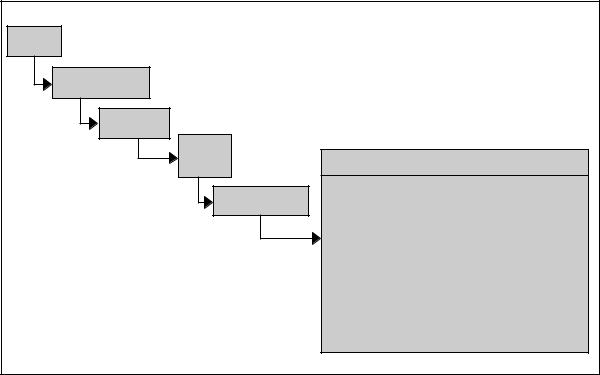
by the Technical Data Package, which will include not only Item Detail Specifications, but also, Process and Material Specifications, as well as drawings, parts lists, and other information that describes the final system in full physical detail. Figure 8-3 shows how these specifications relate to their associated baselines.
Role of Specifications
Requirements documents express why the development is needed. Specification documents are an intermediate expression of what the needed system has to do in terms of technical requirements (function, performance, and interface). Design documents (drawings, associated lists, etc.) describe the means by which the design requirements are to be satisfied. Figure 8-4 illustrates how requirements flow down from top-level specifications to design documentation. Preparation of specifications are part of the system engineering process, but also involve techniques that relate to
74

Chapter 8 |
Systems Engineering Process Outputs |
System |
|
System Definition (Functional Baseline) |
|
|
|
Integrated and |
||
Concept |
P |
|
|
|
Qualified System |
|||
|
|
|
|
|
|
|||
Requirements r |
I |
|
|
|
|
|
|
|
|
o n |
|
System Specification |
|
|
|||
|
d p |
|
|
SI&T |
||||
|
u u |
|
Preliminary Design (Allocated Baseline) |
|
||||
|
c |
t |
|
|
|
|||
|
t |
|
|
|
|
|
|
|
|
|
|
P |
|
|
|
|
|
|
|
Product |
r |
I |
|
|
|
|
|
|
Output |
o n |
|
|
|
|
|
|
|
|
d p |
Item Performance Specifications |
||||
|
|
System |
u u |
|||||
|
|
|
|
|
SI&T |
|||
|
|
Spec |
c |
t |
|
|
|
|
|
|
|
t |
|
|
Detail Design (Product BL) |
||
|
|
|
|
P |
|
|
|
|
|
|
|
|
|
|
|
Item |
|
|
|
|
|
|
r |
I |
|
|
|
|
|
|
Product |
|
Detail |
||
|
|
|
|
Output |
o n |
|
Specs |
|
|
|
|
|
Performance Item Specs |
d p |
|
SI&T |
|
|
|
|
|
u u |
|
|
||
|
|
|
|
|
c |
t |
|
Drawings |
|
|
|
|
|
t |
|
|
|
|
|
|
|
|
|
|
Product |
|
|
|
|
|
|
P |
|
Output |
Process |
|
|
|
|
|
r |
|
|
|
|
|
|
|
|
I |
|
and |
|
|
|
|
|
|
o n |
|
Material |
|
|
|
|
|
|
d p |
|
Specs |
|
|
|
|
|
|
u u |
|
|
|
|
|
|
|
|
c |
t |
|
Drawings |
|
|
|
|
|
t |
|
|
|
SI&T = System Integration and Text |
|
|
|
|
Product |
|
||
|
|
|
|
Output |
|
|||
Figure 8-2. Specifications and Levels of Development
Specification |
Content |
Baseline |
|
|
|
System |
Defines mission/technical performance requirements. |
Functional |
Spec |
Allocates requirements to functional areas and defines interfaces. |
|
|
|
|
Item |
Defines performance characteristics of CIs and CSCIs. |
Allocated |
Performance |
Details design requirements and with drawings and other |
“Design To” |
Spec |
documents form the Allocated Baseline. |
|
|
|
|
Item Detail |
Defines form, fit, function, performance, and test requirements |
Product |
Spec |
for acceptance. (Item, process, and material specs start the |
“Build To” |
|
Product Baseline effort, but the final audited baseline includes |
or |
|
all the items in the TDP.) |
“As Built” |
|
|
|
Process |
Defines process performed during fabrication. |
|
Spec |
|
|
|
|
|
Material |
Defines production of raw materials or semi-fabricated |
|
Spec |
material used in fabrication. |
|
|
|
|
Figure 8-3. Specification Types
75
Systems Engineering Fundamentals |
Chapter 8 |
communication skills, both legal and editorial. Figure 8-5 provides some rules of thumb that illustrate this.
In summary, specifications document what the system has to do, how well it has to do it, and how to verify it can do it.
Baselines
Baselines formally document a product at some given level of design definition. They are references for the subsequent development to follow. Most DoD systems are developed using the three classic baselines described above: functional, allocated, and product. Though the program unique specifications are the dominant baseline documentation, they alone do not constitute a baseline.
Additional documents include both end and enabling product descriptions. End product baseline documents normally include those describing system requirements, functional architecture, physical architecture, technical drawing package,
and requirements traceability. Enabling product baseline documents include a wide range of documents that could include manufacturing plans and processes, supportability planning, supply documentation, manuals, training plans and programs, test planning, deployment planning, and others. All enabling products should be reviewed for their susceptibility to impact from system configuration changes. If a document is one that describes a part of a system and could require change if the configuration changes, then most likely it should be included as a baseline document.
Acquisition Program Baselines
Acquisition Program Baselines and Configuration Baselines are related. To be accurate the Program baseline must reflect the realities of the Configuration Baseline, but the two should not be confused. Acquisition Program Baselines are high level assessments of program maturity and viability. Configuration Baselines are system descriptions. Figure 8-6 provides additional clarification.
System
Spec
Item Performance
Specs
Item
Detail Specs
Process
Material
Specs
Product Baseline
“Build To” Specs
Technical Data Package which includes:
•Engineering Drawings and associated lists
•Technical manuals
•Manufacturing part programs
•Verfication provisions
• Spares provisioning lists
•Specifications, those listed above plus any of the following may be referenced;
–Defense specs
–Commercial item descriptions
–International specs
–Non-government standards
–Commercial standards
–Etc.
Figure 8-4. How Specifications Lead to Design Documents
76