

Диплом ИМЭ, ССК / Диплом / diplom / Приложения / HANDBOOK_DOD-Systems-Engineering-Guide-2001-01
.pdfChapter 13 |
Modeling and Simulation |
CHAPTER 13
MODELING AND
SIMULATION
13.1 INTRODUCTION
A model is a physical, mathematical, or logical representation of a system entity, phenomenon, or process. A simulation is the implementation of a model over time. A simulation brings a model to life and shows how a particular object or phenomenon will behave. It is useful for testing, analysis or training where real-world systems or concepts can be represented by a model.
Modeling and simulation (M&S) provides virtual duplication of products and processes, and
represents those products or processes in readily available and operationally valid environments. Use of models and simulations can reduce the cost and risk of life cycle activities. As shown by Figure 13-1, the advantages are significant throughout the life cycle.
Modeling, Simulation, and Acquisition
Modeling and simulation has become a very important tool across all acquisition-cycle phases and all applications: requirements definition; program management; design and engineering;
$ Savings
Smooth Transition to Operation
•Manual proven
•Trained personnel
•Operationally ready before equipment is given to operators
Saves Time
Prove System Need: Use existing high resolution
models to emulate operational situation
Shortens
Schedules
Need
|
|
Test “concepts” in the “real |
|
|
|
world” of simulation using |
|
Prod |
Concepts |
simple models and putting |
|
Deploy |
operators into process |
||
|
|||
O&S |
|
|
Improves IPPD
|
Detail |
Prelim |
||
|
Design |
Design |
||
Reduce Program Risks |
||||
|
|
|
||
• Design |
|
|
Helps Refine Requirements |
|
• Integration |
|
|
||
|
|
• Get the user involved |
||
• Transition to production |
|
|
||
|
|
• Prevent gold-plating |
||
• Testing |
|
|
||
|
|
|
||
|
|
|
|
|
Sometimes it’s the only way to verify or validate
Figure 13-1. Advantages of Modeling and Simulation
117
Systems Engineering Fundamentals |
Chapter 13 |
efficient test planning; result prediction; supplement to actual test and evaluation; manufacturing; and logistics support. With so many opportunities to use M&S, its four major benefits; cost savings, accelerated schedule, improved product quality and cost avoidance can be achieved in any system development when appropriately applied. DoD and industry around the world have recognized these opportunities, and many are taking advantage of the increasing capabilities of computer and information technology. M&S is now capable of prototyping full systems, networks, interconnecting multiple systems and their simulators so that simulation technology is moving in every direction conceivable.
13.2 CLASSES OF SIMULATIONS
The three classes of models and simulations are virtual, constructive, and live:
•Virtual simulations represent systems both physically and electronically. Examples are aircraft trainers, the Navy’s Battle Force Tactical Trainer, Close Combat Tactical Trainer, and built-in training.
•Constructive simulations represent a system and its employment. They include computer models, analytic tools, mockups, IDEF, Flow Diagrams, and Computer-Aided Design/ Manufacturing (CAD/CAM).
•Live simulations are simulated operations with real operators and real equipment. Examples are fire drills, operational tests, and initial production run with soft tooling.
Virtual Simulation
Virtual simulations put the human-in-the-loop. The operator’s physical interface with the system is duplicated, and the simulated system is made to perform as if it were the real system. The operator is subjected to an environment that looks, feels, and behaves like the real thing. The more advanced version of this is the virtual prototype, which allows the individual to interface with a virtual mockup
operating in a realistic computer-generated environment. A virtual prototype is a computer-based simulation of a system or subsystem with a degree of functional realism that is comparable to that of a physical prototype.
Constructive Simulations
The purpose of systems engineering is to develop descriptions of system solutions. Accordingly, constructive simulations are important products in all key system engineering tasks and activities. Of special interest to the systems engineer are Com- puter-Aided Engineering (CAE) tools. Computeraided tools can allow more in-depth and complete analysis of system requirements early in design. They can provide improved communication because data can be disseminated rapidly to several individuals concurrently, and because design changes can be incorporated and distributed expeditiously. Key computer-aided engineering tools are CAD, CAE, CAM, Continuous Acquisition and Life Cycle Support, and Computer-Aided Systems Engineering:
Computer-Aided Design (CAD). CAD tools are used to describe the product electronically to facilitate and support design decisions. It can model diverse aspects of the system such as how components can be laid out on electrical/electronic circuit boards, how piping or conduit is routed, or how diagnostics will be performed. It is used to lay out systems or components for sizing, positioning, and space allocating using twoor threedimensional displays. It uses three-dimensional “solid” models to ensure that assemblies, surfaces, intersections, interfaces, etc., are clearly defined. Most CAD tools automatically generate isometric and exploded views of detailed dimensional and assembly drawings, and determine component surface areas, volumes, weights, moments of inertia, centers of gravity, etc. Additionally, many CAD tools can develop three-dimensional models of facilities, operator consoles, maintenance workstations, etc., for evaluating man-machine interfaces. CAD tools are available in numerous varieties, reflecting different degrees of capabilities, fidelity, and cost. The commercial CAD/CAM product, Computer-Aided Three-Dimensional
118
Chapter 13 |
Modeling and Simulation |
Interactive Application (CATIA), was used to develop the Boeing 777, and is a good example of current state-of-the-art CAD.
Computer-Aided Engineering (CAE). CAE provides automation of requirements and performance analyses in support of trade studies. It normally would automate technical analyses such as stress, thermodynamic, acoustic, vibration, or heat transfer analysis. Additionally, it can provide automated processes for functional analyses such as fault isolation and testing, failure mode, and safety analyses. CAE can also provide automation of life- cycle-oriented analysis necessary to support the design. Maintainability, producibility, human factor, logistics support, and value/cost analyses are available with CAE tools.
Computer-Aided Manufacturing (CAM). CAM tools are generally designed to provide automated support to both production process planning and to the project management process. Process planning attributes of CAM include establishing Numerical Control parameters, controlling machine tools using pre-coded instructions, programming robotic machinery, handling material, and ordering replacement parts. The production management aspect of CAM provides management control over production-relevant data, uses historical actual costs to predict cost and plan activities, identifies schedule slips or slack on a daily basis, and tracks metrics relative to procurement, inventory, forecasting, scheduling, cost reporting, support, quality, maintenance, capacity, etc. A common example of a computer-based project planning and control tool is Manufacturing Resource Planning II (MRP II). Some CAM programs can accept data direct from a CAD program. With this type of tool, generally referred to as CAD/CAM, substantial CAM data is automatically generated by importing the CAD data directly into the CAM software.
Computer-Aided Systems Engineering (CASE).
CASE tools provide automated support for the Systems Engineering and associated processes. CASE tools can provide automated support for integrating system engineering activities, performing the systems engineering tasks outlined in
previous chapters, and performing the systems analysis and control activities. It provides technical management support and has a broader capability than either CAD or CAE. An increasing variety of CASE tools are available, as competition brings more products to market, and many of these support the commercial “best Systems Engineering practices.”
Continuous Acquisition and Life Cycle Support (CALS). CALS relates to the application of computerized technology to plan and implement support functions. The emphasis is on information relating to maintenance, supply support, and associated functions. An important aspect of CALS is the importation of information developed during design and production. A key CALS function is to support the maintenance of the system configuration during the operation and support phase. In DoD, CALS supports activities of the logistics community rather than the specific program office, and transfer of data between the CAD or CAM programs to CALS has been problematic. As a result there is current emphasis on development of standards for compatible data exchange. Formats of import include: twoand three-dimensional models (CAD), ASCII formats (Technical Manuals), two-dimensional illustrations (Technical Manuals), and Engineering Drawing formats (Raster, Aperture cards). These formats will be employed in the Integrated Data Environment (IDE) that is mandated for use in DoD program offices.
Live Simulation
Live simulations are simulated operations of real systems using real people in realistic situations. The intent is to put the system, including its operators, through an operational scenario, where some conditions and environments are mimicked to provide a realistic operating situation. Examples of live simulations range from fleet exercises to fire drills.
Eventually live simulations must be performed to validate constructive and virtual simulations. However, live simulations are usually costly, and trade studies should be performed to support the balance of simulation types chosen for the program.
119
Systems Engineering Fundamentals |
Chapter 13 |
13.3 HARDWARE VERSUS SOFTWARE
Though current emphasis is on software M&S, the decision of whether to use hardware, software, or a combined approach is dependent on the complexity of the system, the flexibility needed for the simulation, the level of fidelity required, and the potential for reuse. Software capabilities are increasing, making software solutions cost effective for large complex projects and repeated processes. Hardware methods are particularly useful for validation of software M&S, simple or onetime projects, and quick checks on changes of production systems. M&S methods will vary widely in cost. Analysis of the cost-versus-benefits of potential M&S methods should be performed to support planning decisions.
13.4VERIFICATION, VALIDATION, AND ACCREDITATION
How can you trust the model or simulation? Establish confidence in your model or simulation through formal verification, validation, and accreditation (VV&A). VV&A is usually identified with software, but the basic concept applies to
hardware as well. Figure 13-2 shows the basic differences between the terms (VV&A).
More specifically:
•Verification is the process of determining that a model implementation accurately represents the developer’s conceptual description and specifications that the model was designed to.
•Validation is the process of determining the manner and degree to which a model is an accurate representation of the real world from the perspective of the intended uses of the model, and of establishing the level of confidence that should be placed on this assessment.
•Accreditation is the formal certification that a model or simulation is acceptable for use for a specific purpose. Accreditation is conferred by the organization best positioned to make the judgment that the model or simulation in question is acceptable. That organization may be an operational user, the program office, or a contractor, depending upon the purposes intended.
Verification |
Validation |
Accreditation |
“It works as I |
|
“It suits my needs.” |
thought it would.” |
|
|
|
|
|
|
“It looks just like |
|
|
the real thing.” |
|
Developer |
Functional Expert |
Requester/User |
Verification Agent |
Validation Agent |
Accreditation Agent |
As design matures, re-examine basic assumptions.
Figure 13-2. Verification, Validation, and Accreditation
120
Chapter 13 |
Modeling and Simulation |
VV&A is particularly necessary in cases where:
•Complex and critical interoperability is being represented,
•Reuse is intended,
•Safety of life is involved, and
•Significant resources are involved.
VV&A Currency
Note of caution: Don’t confuse the quality of the display with the quality of meeting simulation needs! An example of fidelity is a well-known flight simulator using a PC and simple joystick versus a full 6-degree of freedom fully-instru- mented aircraft cockpit. Both have value at different stages of flight training, but obviously vary significantly in cost from thousands of dollars to millions. This cost difference is based on fidelity, or degree of real-world accuracy.
Planning
VV&A is applied at initial development and use. The VV&A process is required for all DoD simulations and should be redone whenever existing models and simulations undergo a major upgrade or modification. Additionally, whenever the model or simulation violates its documented methodology or inherent boundaries that were used to validate or verify by its different use, then VV&A must be redone. Accreditation, however, may remain valid for the specific application unless revoked by the Accreditation Agent, as long as its use or what it simulates doesn’t change.
13.5 CONSIDERATIONS
There are a number of considerations that should enter into decisions regarding the acquisition and employment of modeling and simulation in defense acquisition management. Among these are such concerns as cost, fidelity, planning, balance, and integration.
Cost Versus Fidelity
Fidelity is the degree to which aspects of the real world are represented in M&S. It is the foundation for development of the model and subsequent VV&A. Cost effectiveness is a serious issue with simulation fidelity, because fidelity can be an aggressive cost driver. The correct balance between cost and fidelity should be the result of simulation need analysis. M&S designers and VV&A agents must decide when enough is enough. Fidelity needs can vary throughout the simulation. This variance should be identified by analysis and planned for.
Planning should be an inherent part of M&S, and, therefore, it must be proactive, early, continuous, and regular. Early planning will help achieve balance and beneficial reuse and integration. With computer and simulation technologies evolving so rapidly, planning is a dynamic process. It must be a continuing process, and it is important that the appropriate simulation experts be involved to maximize the use of new capabilities. M&S activities should be a part of the integrated teaming and involve all responsible organizations. Integrated teams must develop their M&S plans and insert them into the overall planning process, including the TEMP, acquisition strategy, and any other program planning activity.
M&S planning should include:
•Identification of activities responsible for each VV&A element of each model or simulation, and
•Thorough VV&A estimates, formally agreed to by all activities involved in M&S, including T&E commitments from the developmental testers, operational testers, and separate VV&A agents.
Those responsible for the VV&A activities must be identified as a normal part of planning. Figure 13-2 shows the developer as the verification agent, the functional expert as the validation agent, and the user as the accreditation agent. In general this is appropriate for virtual simulations. However, the manufacturer of a constructive simulation would usually be expected to justify or warrantee their
121
Systems Engineering Fundamentals |
Chapter 13 |
program’s use for a particular application. The question of who should actually accomplish VV&A is one that is answered in planning. VV&A requirements should be specifically called out in tasking documents and contracts. When appropriate, VV&A should be part of the contractor’s proposal, and negotiated prior to contract award.
Balance
Balance refers to the use of M&S across the phases of the product life cycle and across the spectrum of functional disciplines involved. The term may further refer to the use of hardware versus software, fidelity level, VV&A level, and even use versus non-use. Balance should always be based on cost effectiveness analysis. Cost effectiveness analyses should be comprehensive; that is, M&S should be properly considered for use in all parallel applications and across the complete life cycle of the system development and use.
Integration
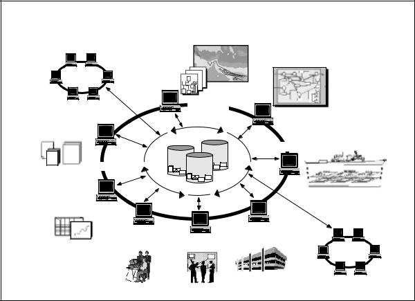
Integration is obtained by designing a model or simulation to inter-operate with other models or simulations for the purpose of increased performance, cost benefit, or synergism. Multiple benefits or savings can be gained from increased synergism and use over time and across activities. Integration is achieved through reuse or upgrade of legacy programs used by the system, or of the proactive planning of integrated development of new simulations. In this case integration is accomplished through the planned utilization of models, simulations, or data for multiple times or applications over the system life cycle. The planned upgrade of M&S for evolving or parallel uses supports the application of open systems architecture to the system design. M&S efforts that are established to perform a specific function by a specific contractor, subcontractor, or government activity will tend to be sub-optimized. To achieve
Another |
Concept |
|
Development |
||
System |
||
|
Functional
Design
Distributed
Framework
Requirements
Distributed |
|
Physical and |
Repository |
HW/SW Design |
Program |
|
|
|
Mgmt |
|
Another |
|
|
|
System |
|
Opns, Log |
|
Eng Dev |
|
|
and Manuf |
||
and Training |
Testing |
||
|
Figure 13-3. A Robust Integrated Use of Simulation Technology
122
Chapter 13 |
Modeling and Simulation |
integration M&S should be managed at least at the program office level.
The Future Direction
DoD, the Services, and their commands have strongly endorsed the use of M&S throughout the acquisition life cycle. The supporting simulation technology is also evolving as fast as computer technology changes, providing greater fidelity and flexibility. As more simulations are interconnected, the opportunities for further integration expand. M&S successes to date also accelerate its use. The current focus is to achieve open systems of simulations, so they can be plug-and-play across the spectrum of applications. From concept analysis through disposal analysis, programs may use hundreds of different simulations, simulators and model analysis tools. Figure 13-3 shows conceptually how an integrated program M&S would affect the functions of the acquisition process.
A formal DoD initiative, Simulation Based Acquisition (SBA), is currently underway. The SBA vision is to advance the implementation of M&S in the DoD acquisition process toward a robust, collaborative use of simulation technology that is integrated across acquisition phases and programs. The result will be programs that are much better integrated in an IPPD sense, and which are much more efficient in the use of time and dollars expended to meet the needs of operational users.
13.6 SUMMARY
•M&S provides virtual duplication of products and processes, and represent those products or processes in readily available and operationally valid environments.
•M&S should be applied throughout the system life cycle in support of systems engineering activities.
•The three classes of models and simulations are virtual, constructive, and live.
•Establish confidence in your model or simulation through formal VV&A.
•M&S planning should be an inherent part of Systems Engineering planning, and, therefore, pro-active, early, continuous, and regular.
•A more detailed discussion of the use and management of M&S in DoD acquisition is available in the DSMC publication Systems Acquisition Manager’s Guide for the Use of Models and Simulations.
•An excellent second source is the DSMC publication, Simulation Based Acquisition – A New Approach. It surveys applications of increasing integration of simulation in current DoD programs and the resulting increasing benefits through greater integration.
123
Systems Engineering Fundamentals |
Chapter 13 |
124
Chapter 14 |
Metrics |
CHAPTER 14
METRICS
14.1 METRICS IN MANAGEMENT
Metrics are measurements collected for the purpose of determining project progress and overall condition by observing the change of the measured quantity over time. Management of technical activities requires use of three basic types of metrics:
•Product metrics that track the development of the product,
•Earned Value which tracks conformance to the planned schedule and cost, and
•Management process metrics that track management activities.
Measurement, evaluation and control of metrics is accomplished through a system of periodic reporting must be planned, established, and monitored to assure metrics are properly measured, evaluated, and the resulting data disseminated.
Product Metrics
Product metrics are those that track key attributes of the design to observe progress toward meeting customer requirements. Product metrics reflect three basic types of requirements: operational performance, life-cycle suitability, and affordability. The key set of systems engineering metrics are the Technical Performance Measurements (TPM.) TPMs are product metrics that track design progress toward meeting customer performance requirements. They are closely associated with the system engineering process because they directly support traceability of operational needs to the design effort. TPMs are derived from Measures of Performance (MOPs) which reflect system requirements. MOPs are derived from Measures of
Effectiveness (MOEs) which reflect operational performance requirements.
The term “metric” implies quantitatively measurable data. In design, the usefulness of metric data is greater if it can be measured at the configuration item level. For example, weight can be estimated at all levels of the WBS. Speed, though an extremely important operational parameter, cannot be allocated down through the WBS. It cannot be measured, except through analysis and simulation, until an integrated product is available. Since weight is an important factor in achieving speed objectives, and weight can be measured at various levels as the system is being developed, weight may be the better choice as a metric. It has a direct impact on speed, so it traces to the operational requirement, but, most importantly, it can be allocated throughout the WBS and progress toward achieving weight goals may then be tracked through development to production.
Measures of Effectiveness and Suitability
Measures of Effectiveness (MOEs) and Measures of Suitability (MOSs) are measures of operational effectiveness and suitability in terms of operational outcomes. They identify the most critical performance requirements to meet system-level mission objectives, and will reflect key operational needs in the operational requirements document.
Operational effectiveness is the overall degree of a system’s capability to achieve mission success considering the total operational environment. For example, weapon system effectiveness would consider environmental factors such as operator organization, doctrine, and tactics; survivability; vulnerability; and threat characteristics. MOSs, on the other hand, would measure the extent to which the system integrates well into the operation
125
Systems Engineering Fundamentals |
Chapter 14 |
environment and would consider such issues as supportability, human interface compatibility, and maintainability.
Measures of Performance
MOPs characterize physical or functional attributes relating to the execution of the mission or function. They quantify a technical or performance requirement directly derived from MOEs and MOSs. MOPs should relate to these measures such that a change in MOP can be related to a change in MOE or MOS. MOPs should also reflect key performance requirements in the system specification. MOPs are used to derive, develop, support, and document the performance requirements that will be the basis for design activities and process development. They also identify the critical technical parameters that will be tracked through TPMs.
Technical Performance Measurements
TPMs are derived directly from MOPs, and are selected as being critical from a periodic review and control standpoint. TPMs help assess design progress, assess compliance to requirements throughout the WBS, and assist in monitoring and tracking technical risk. They can identify the need for deficiency recovery, and provide information to support cost-performance sensitivity assessments. TPMs can include range, accuracy, weight, size, availability, power output, power required, process time, and other product characteristics that relate directly to the system operational requirements.
TPMs traceable to WBS elements are preferred, so elements within the system can be monitored as well as the system as a whole. However, some necessary TPMs will be limited to the system or subsystem level. For example, the specific fuel consumption of an engine would be a TPM necessary to track during the engine development, but it is not allocated throughout the WBS. It is reported as a single data item reflecting the performance of the engine as a whole. In this case the metric will indicate that the design approach is consistent with
the required performance, but it may not be useful as an early warning device to indicate progress toward meeting the design goal. A more detailed discussion of TPMs is available as Supplement A to this chapter.
Example of Measures
MOE: The vehicle must be able to drive fully loaded from Washington, DC, to Tampa on one tank of fuel.
MOP: Vehicle range must be equal to or greater than 1,000 miles.
TPM: Fuel consumption, vehicle weight, tank size, drag, power train friction, etc.
Suitability Metrics
Tracking metrics relating to operational suitability and other life cycle concerns may be appropriate to monitor progress toward an integrated design. Operational suitability is the degree to which a system can be placed satisfactorily in field use considering availability, compatibility, transportability, interoperability, reliability, usage rates, maintainability, safety, human factors, documentation, training, manpower, supportability, logistics, and environmental impacts. These suitability parameters can generate product metrics that indicate progress toward an operationally suitable system. For example, factors that indicate the level of automation in the design would reflect progress toward achieving manpower quantity and quality requirements. TPMs and suitability product metrics commonly overlap. For example, Mean Time Between Failure (MBTF) can reflect both effectiveness or suitability requirements.
Suitability metrics would also include measurements that indicate improvement in the producibility, testability, degree of design simplicity, and design robustness. For example, tracking number of parts, number of like parts, and number of wearing parts provides indicators of producibility, maintainability, and design simplicity.
126