

2MBI200S-120 |
IGBT Module |
1200V / 200A 2 in one-package |
|

 Features
·High speed switching
·Voltage drive
·Low inductance module structure

 Applications
·Inverter for Motor drive
·AC and DC Servo drive amplifier
·Uninterruptible power supply
·Industrial machines, such as Welding machines
Maximum ratings and characteristics |
|
|
|
|
|
||||
Absolute maximum ratings (at Tc=25°C unless otherwise specified) |
Equivalent Circuit Schematic |
||||||||
Item |
|
|
Symbol |
Rating |
Unit |
||||
Collector-Emitter voltage |
|
VCES |
1200 |
V |
|
C2E1 |
|
|
|
Gate-Emitter voltaga |
|
VGES |
±20 |
V |
|
|
|
|
|
Collector |
Continuous |
Tc=25°C |
IC |
300 |
A |
C1 |
|
|
E2 |
current |
|
Tc=80°C |
|
200 |
A |
|
|
|
|
|
1ms |
Tc=25°C |
IC pulse |
600 |
A |
|
|
|
|
|
|
Tc=80°C |
|
400 |
A |
|
|
|
|
|
|
|
-IC |
200 |
A |
|
|
|
|
|
1ms |
|
-IC pulse |
400 |
A |
|
|
|
|
Max. power dissipation |
|
PC |
1500 |
W |
G1 |
E1 |
G2 |
E2 |
|
Operating temperature |
|
Tj |
+150 |
°C |
|||||
|
|
|
|
|
|||||
Storage temperature |
|
Tstg |
-40 to +125 |
°C |
|
|
|
|
|
Isolation voltage *1 |
|
Vis |
AC 2500 (1min. ) |
V |
|
|
|
|
|
Screw torque |
|
Mounting *2 |
3.5 |
N·m |
|
|
|
|
|
|
|
|
Terminals *2 |
4.5 |
N·m |
|
|
|
|
*1 : Aii terminals should be connected together when isolation test will be done
*2 : Recommendable value : Mounting 2.5 to 3.5 N·m(M5 or M6)
Terminals 3.5 to 4.5 N·m(M6)
 Electrical characteristics (at Tj=25°C unless otherwise specified)
Item |
Symbol |
Characteristics |
|
Conditions |
Unit |
|||
|
|
Min. |
Typ. |
Max. |
|
|
|
|
Zero gate voltage collector current |
ICES |
– |
– |
1.0 |
VGE=0V, VCE=1200V |
mA |
||
Gate-Emitter leakage current |
IGES |
– |
– |
0.4 |
VCE=0V, VGE=±20V |
µA |
||
Gate-Emitter threshold voltage |
VGE(th) |
5.5 |
7.2 |
8.5 |
VCE=20V, IC=200mA |
V |
||
Collector-Emitter saturation voltage |
VCE(sat) |
– |
2.3 |
2.6 |
Tc=25° C |
|
VGE=15V, IC=200A |
V |
|
|
– |
2.8 |
– |
Tc=125°C |
|
|
|
Input capacitance |
Cies |
– |
24000 |
– |
VGE=0V |
|
pF |
|
Output capacitance |
Coes |
– |
5000 |
– |
VCE=10V |
|
|
|
Reverse transfer capacitance |
Cres |
– |
4400 |
– |
f=1MHz |
|
|
|
Turn-on time |
ton |
– |
0.35 |
1.2 |
VCC=600V |
|
µs |
|
|
tr |
– |
0.25 |
0.6 |
IC=200A |
|
|
|
|
tr(i) |
– |
0.1 |
– |
VGE=±15V |
|
|
|
Turn-off time |
toff |
– |
0.45 |
1.0 |
RG=4.7 ohm |
|
||
|
tf |
– |
0.08 |
0.3 |
|
|
|
|
Forward on voltage |
VF |
– |
2.3 |
3.0 |
Tj=25°C |
|
IF=200A, VGE=0V |
V |
|
|
– |
2.0 |
– |
Tj=125°C |
|
|
|
Reverse recovery time |
trr |
– |
– |
0.35 |
IF=200A |
|
µs |
|
 Thermal resistance characteristics
Item |
Symbol |
Characteristics |
|
Conditions |
Unit |
|
|
|
Min. |
Typ. |
Max. |
|
|
Thermal resistance |
Rth(j-c) |
– |
– |
0.085 |
IGBT |
°C/W |
|
Rth(j-c) |
– |
– |
0.18 |
Diode |
°C/W |
|
Rth(c-f)*2 |
– |
0.025 |
– |
the base to cooling fin |
°C/W |
*2 : This is the value which is defined mounting on the additional cooling fin with thermal compound
2MBI200S-120 |
IGBT Module |

 Characteristics (Representative)
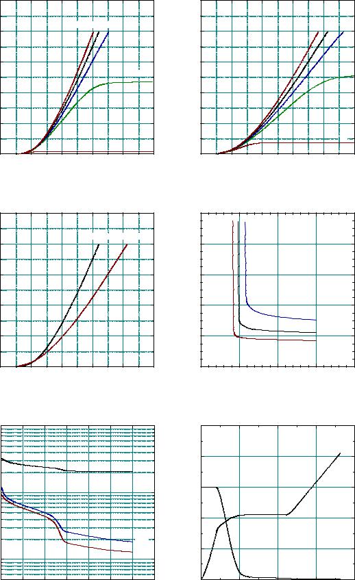
Collector current vs. Collector-Emiiter voltage
Tj= 25°C (typ.)
|
500 |
|
|
|
|
|
|
|
|
400 |
|
|
VGE= 20V15V 12V |
|
|||
|
|
|
|
|
|
|
|
|
[ A ] |
|
|
|
|
|
|
|
|
Ic |
300 |
|
|
|
|
|
|
|
: |
|
|
|
|
|
|
|
|
current |
|
|
|
|
|
|
|
10V |
200 |
|
|
|
|
|
|
|
|
Collector |
|
|
|
|
|
|
|
|
|
|
|
|
|
|
|
|
|
|
100 |
|
|
|
|
|
|
|
|
0 |
|
|
|
|
|
|
8V |
|
1 |
2 |
3 |
|
|
4 |
5 |
|
|
0 |
|
|
|||||
|
|
Collector - Emitter voltage |
: |
VCE |
[ V ] |
|
||
Collector current vs. Collector-Emiiter voltage
Tj= 125°C (typ.)
|
500 |
|
|
|
|
|
|
|
|
|
|
|
VGE= 20V 15V |
12V |
|
|
400 |
|
|
|
|
|
|
[ A ] |
|
|
|
|
|
|
|
: Ic |
300 |
|
|
|
|
|
10V |
|
|
|
|
|
|
||
current |
200 |
|
|
|
|
|
|
Collector |
|
|
|
|
|
|
|
|
|
|
|
|
|
|
|
|
100 |
|
|
|
|
|
|
|
|
|
|
|
|
|
8V |
|
0 |
1 |
2 |
3 |
|
4 |
5 |
|
0 |
|
|||||
|
|
Collector - Emitter voltage |
: VCE |
[ V ] |
|
||
|
|
Collector current |
vs. Collector-Emiiter voltage |
|
||
|
500 |
|
VGE=15V (typ.) |
|
|
|
|
|
|
|
|
|
|
|
400 |
|
|
Tj= 25°C |
Tj= 125°C |
|
|
|
|
|
|
] |
|
|
|
|
|
|
|
[ V |
[ A ] |
|
|
|
|
|
VCE |
Collectorcurrent : Ic |
300 |
|
|
|
|
Emitter-Collectorvoltage : |
200 |
|
|
|
|
||
|
|
|
|
|
|
|
|
100 |
|
|
|
|
|
|
0 |
1 |
2 |
3 |
4 |
5 |
|
0 |
|||||
|
|
Collector - Emitter voltage : VCE |
[ V ] |
|
||
Collector-Emiiter voltage vs. Gate-Emitter voltage
Tj= 25°C (typ.)
10
8
6 |
|
|
4 |
|
|
|
Ic= 400A |
|
2 |
Ic= 200A |
|
Ic=100A |
||
|
||
0 |
|
5 |
10 |
15 |
20 |
25 |
|
Gate - Emitter voltage : |
VGE [ V ] |
|
|
Capacitance vs. Collector-Emiiter voltage (typ.) |
Dynamic Gate charge (typ.) |
VGE=0V, f= 1MHz, Tj= 25°C |
Vcc=600V, Ic=200A, Tj= 25°C |
|
100000 |
|
|
|
|
|
|
|
|
1000 |
] |
|
|
|
|
|
|
|
|
] |
800 |
pF |
|
|
|
|
|
|
|
Cies |
[ V |
|
[ |
|
|
|
|
|
|
|
VCE |
|
|
Cres |
|
|
|
|
|
|
|
|
||
|
|
|
|
|
|
|
|
600 |
||
Capacitance : Cies, Coes, |
10000 |
|
|
|
|
|
|
|
Collector - Emitter voltage : |
|
|
|
|
|
|
|
|
|
|||
5000 |
|
|
|
|
|
|
|
400 |
||
|
|
|
|
|
|
|
|
|||
|
|
|
|
|
|
|
Coes |
|
||
|
|
|
|
|
|
|
Cres |
200 |
||
|
1000 |
|
|
|
|
|
|
|
|
|
|
|
|
|
|
|
|
|
|
|
|
|
500 |
5 |
10 |
15 |
20 |
|
25 |
30 |
35 |
0 |
|
0 |
|
|
|||||||
|
|
|
Collector - Emitter voltage |
: |
VCE |
[ V ] |
|
|
||
|
|
|
|
25 |
|
|
|
|
|
20 |
|
|
|
|
|
|
[ V ] |
|
|
|
|
15 |
VGE |
|
|
|
|
: |
|
|
|
|
|
|
|
|
|
|
|
|
voltage |
|
|
|
|
10 |
Gate - Emitter |
|
|
|
|
5 |
|
|
|
|
|
|
|
0 |
500 |
1000 |
1500 |
0 |
|
2000 |
|
Gate charge : Qg [ nC ]
2MBI200S-120 |
IGBT Module |
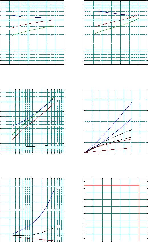
Switching time : ton, tr, toff, tf [ nsec ]
Switching time vs. Collector current (typ.)
Vcc=600V, VGE=±15V, Rg= 4.7ohm, Tj= 25°C
1000 |
|
|
|
500 |
toff |
|
] |
|
|
[ nsec |
|
|
|
|
|
|
ton |
|
tr, toff, tf |
|
|
|
ton, |
|
tr |
|
: |
|
|
time |
|
|
|
|
|
100 |
|
|
Switching |
|
|
|
|
|
tf |
|
|
50 |
100 |
200 |
300 |
0 |
|||
|
Collector current : Ic |
[ A ] |
|
Switching time vs. Collector current (typ.) Vcc=600V, VGE=±15V, Rg= 4.7ohm, Tj= 125°C
1000 |
|
|
|
|
toff |
|
|
500 |
|
|
|
|
ton |
|
|
|
tr |
|
|
|
tf |
|
|
100 |
|
|
|
50 |
100 |
200 |
300 |
0 |
|||
|
Collector current : Ic |
[ A ] |
|
Switching time vs. Gate resistance (typ.)
Vcc=600V, Ic=200A, VGE=±15V, Tj= 25°C
|
5000 |
|
|
|
|
|
|
|
ton |
|
|
|
|
toff |
] |
|
|
|
tr |
tf [ nsec |
1000 |
|
|
|
tr, toff, |
500 |
|
|
|
ton, |
|
|
|
|
|
|
|
|
|
: |
|
|
|
|
Switching time |
100 |
|
|
tf |
|
|
|
||
|
50 |
10 |
|
100 |
|
1 |
|
||
|
|
Gate resistance |
: Rg |
[ohm] |
Switching loss vs. Collector current (typ.)
Vcc=600V, VGE=±15V, Rg=4.7ohm
|
60 |
|
|
|
|
|
|
] |
|
|
|
|
|
Eon(125°C) |
|
[ mJ/pulse |
|
|
|
|
|
|
|
40 |
|
|
|
|
|
|
|
Err |
|
|
|
|
|
|
|
Eon, Eoff, |
|
|
|
|
|
Eon(25°C) |
|
|
|
|
|
|
|
|
|
: |
|
|
|
|
|
Eoff(125°C) |
|
loss |
20 |
|
|
|
|
|
|
|
|
|
|
|
|
||
|
|
|
|
|
Eoff(25°C) |
|
|
Switching |
|
|
|
|
|
|
|
|
|
|
|
|
Err(125°C) |
|
|
|
|
|
|
|
|
|
|
|
|
|
|
|
|
Err(25°C) |
|
|
0 |
100 |
200 |
|
|
300 |
400 |
|
0 |
|
|
||||
|
|
|
Collector current |
: |
Ic |
[ A ] |
|
Switching loss vs. Gate resistance (typ.)
Vcc=600V, Ic=200A, VGE=±15V, Tj= 125°C
|
160 |
|
|
|
] |
|
|
|
Eon |
mJ/pulse[ |
120 |
|
|
]A |
|
|
|
|
|
Err |
|
|
|
Ic [ |
Eon,:lossSwitchingEoff, |
80 |
|
|
currentCollector: |
|
|
|
|
|
|
40 |
|
|
Eoff |
|
|
|
|
|
|
|
|
|
Err |
|
0 |
10 |
|
100 |
|
1 |
|
||
|
|
Gate resistance |
: Rg |
[ohm] |
Reverse bias safe operating area +VGE=15V, -VGE=<15V, Rg=>4.7ohm, Tj=<125°C
450
400
350
300
250
200
150
100
50
0
0 |
200 |
400 |
600 |
800 |
1000 |
1200 |
1400 |
Collector - Emitter voltage : VCE [ V ]

2MBI200S-120 |
IGBT Module |
|
Forward current vs. Forward on voltage (typ.) |
Reverse recovery characteristics (typ.) |
|
Vcc=600V, VGE=±15V, Rg=4.7ohm |
||
|
|
500 |
|
|
|
|
|
|
500 |
|
|
|
|
|
400 |
|
|
Tj=125°C |
Tj=25°C |
|
|
|
|
|
|
|
|
|
|
|
|
|
|
|
|
|
|
|
|
|
|
|
|
|
|
] ] |
|
|
Irr(125°C) |
|
|
|
|
|
|
|
|
|
Irr [ A [ nsec |
|
|
|
|
||
[ A ] |
300 |
|
|
|
|
|
|
trr(125°C) |
|
|
||
Forward current : IF |
|
|
|
|
Reverse recovery current : |
Reverse recovery time : trr |
100 |
|
Irr(25°C) |
|
|
|
|
|
|
|
|
|
|
trr(25°C) |
|
|
|||
200 |
|
|
|
|
|
|
|
|
|
|||
100 |
|
|
|
|
|
|
|
|
|
|||
|
|
|
|
|
|
|
|
|
|
|||
|
0 |
1 |
2 |
|
3 |
4 |
|
10 |
0 |
100 |
200 |
300 |
|
0 |
|
|
|
||||||||
|
|
|
Forward on voltage |
: VF |
[ V ] |
|
|
|
|
Forward current : IF |
[ A ] |
|
Transient thermal resistance
|
1 |
|
|
|
] |
|
|
|
FWD |
[ °C/W |
0.1 |
|
|
|
Rth(j-c) |
|
|
|
|
0.05 |
|
|
IGBT |
|
|
|
|
|
|
: |
|
|
|
|
resistanse |
0.01 |
|
|
|
Thermal |
|
|
|
|
|
1E-3 |
0.01 |
0.1 |
1 |
|
0.001 |
|||
|
|
Pulse width : Pw [ sec ] |
|
|
Outline Drawings, mm |
|
|
||
mass : 370g