

- •Legal notices
- •Contents
- •Chapter 1: What's new
- •What’s new (CS5.5)
- •What’s new (CS5)
- •Chapter 2: User interface
- •Workspaces
- •Import a workspace with a project
- •Customizing workspaces
- •About workspaces
- •Choose a workspace
- •Dock, group, or float panels
- •Resize panel groups
- •Open, close, and scroll to panels
- •Working with multiple monitors
- •Save, reset, or delete workspaces
- •Brighten or darken the interface
- •Working with Panels
- •Navigate the panels
- •Display any panel full-screen
- •Display panel options
- •Display context and panel menus
- •Tools panel and Options panel
- •Tools
- •Open the Options panel
- •Dock the Tools panel to the Options panel
- •Undock the Tools panel from the Options panel
- •Clip details in the Info panel
- •Preferences
- •Change preferences
- •General preferences
- •Appearance preferences
- •Audio Preferences
- •Audio Hardware preferences
- •Audio Output Mapping preferences
- •Change the Auto Save settings
- •Capture preferences
- •Device Control preferences
- •Label Colors preferences
- •Label Defaults preferences
- •Media preferences
- •Memory preferences
- •Player Settings preferences
- •Titler preferences
- •Trim preferences
- •Chapter 3: Workflows and setup
- •Basic workflow
- •Cross-platform workflow
- •Cross-application workflows
- •Edit a clip in its original application
- •Working with Photoshop and Premiere Pro
- •Create and edit Photoshop files
- •Copy between After Effects and Adobe Premiere Pro
- •Copy from After Effects to Adobe Premiere Pro
- •Results of pasting into Adobe Premiere Pro
- •Copy from Adobe Premiere Pro to After Effects
- •Results of pasting into After Effects
- •Working with Adobe Premiere Pro and Adobe Flash
- •Working with Adobe Story, Adobe OnLocation, and Adobe Premiere Pro
- •Import clips with In and Out points set in Adobe OnLocation
- •Working with Encore and Premiere Pro
- •Add Encore chapter markers
- •Send to Encore or to an MPEG-2 file
- •Working with Final Cut Pro and Adobe Premiere Pro
- •Working with Avid Media Composer and Premiere Pro
- •Adobe Dynamic Link
- •About Dynamic Link (Production Premium or Master Collection only)
- •Dynamic Link performance (Production Premium or Master Collection only)
- •Create and link to After Effects compositions with Dynamic Link (Production Premium or Master Collection only)
- •Create a composition from clips in Adobe Premiere Pro
- •Create a dynamically linked composition from Adobe Premiere Pro or Encore
- •Link to an existing composition
- •Delete a dynamically linked composition or clip (Production Premium or Master Collection only)
- •Modify a dynamically linked composition in After Effects (Production Premium or Master Collection only)
- •Create an After Effects composition from clips in Premiere Pro (Production Premium only)
- •Offline compositions and Dynamic Link (Production Premium or Master Collection only)
- •Take a dynamically linked composition offline
- •Relink a dynamically linked composition
- •Setting up your system
- •Premiere Pro trial versions
- •Set up a DV or HDV system
- •Set up an SD-SDI, HD-SDI, or component system
- •Set up a file-based system
- •Set up an S-Video or composite system
- •Specify the default audio device
- •Audio Hardware Settings (Windows only)
- •Set up a USB microphone (Mac OS)
- •Specify ASIO device settings (Windows only)
- •Specify whether to render audio when rendering video
- •Specify the duration for preroll and postroll pauses
- •Specify scratch disks to improve system performance
- •Specify scratch disks
- •Optimizing scratch disk performance
- •Online resources for improving system performance
- •Move or clean the Media Cache Database
- •Optimize rendering for available memory
- •Chapter 4: Project setup
- •Creating and changing projects
- •Create a project
- •Review project settings
- •Project Settings dialog box
- •Open a project
- •Delete a project file
- •Moving a project to another computer
- •Archiving projects
- •Trim or copy your project
- •Chapter 5: Importing, transferring, capturing, and digitizing
- •Transferring and importing files
- •File formats supported for import
- •About transferring files
- •About importing files
- •Import files with the Media Browser
- •Import files with the Import commands
- •Import files using Adobe Bridge
- •Start Adobe Bridge from Adobe Premiere Pro
- •Import files from Adobe Bridge
- •Channel support
- •Importing assets from tapeless formats
- •Import assets from file-based sources with Media Browser
- •About spanned clips
- •Importing still images
- •Preparing still images before importing
- •Importing Photoshop and Illustrator files
- •Import a layered Photoshop file
- •Importing Illustrator images
- •Import numbered still-image sequences as video clips
- •Importing digital audio
- •Using audio from audio CDs
- •Using compressed audio formats
- •Using audio from Adobe Soundbooth
- •Audio sample rates supported
- •Conforming audio
- •Importing sequences, clip lists, libraries, and compositions
- •Import clips from Adobe OnLocation projects using the Media Browser
- •Importing earlier Premiere Pro projects
- •Import selected sequences from Premiere Pro projects
- •Import a Premiere Elements project (Windows only)
- •Importing libraries (Windows only)
- •Importing After Effects compositions
- •Import After Effects compositions
- •Import CMX3600 EDL projects
- •Importing XML project files from Final Cut Pro
- •Import an XML file from Final Cut Pro
- •Final Cut Pro clip data
- •Final Cut Pro effects and transitions
- •Conversion of Final Cut Pro video effects
- •Conversion of Final Cut Pro video transitions
- •Conversion of Final Cut Pro audio effects
- •Conversion of Final Cut Pro audio transitions
- •Final Cut Pro composite modes
- •Final Cut Pro Multiclips
- •Capturing and digitizing
- •About capturing and digitizing
- •System requirements for capturing
- •Set capture format, preferences, and tracks
- •Specify capture settings
- •Set capture preferences
- •Select tracks for capture
- •Capture from stereo sources to mono tracks
- •File size limits
- •Set up device control
- •Disable device control
- •Capture without device control
- •Capture with device control
- •Capture an entire tape or portion of a tape
- •Select and capture a clip
- •Determine whether your device is online
- •Log clips with automatic scene detection
- •Common capture issues
- •Capturing DV or HDV video
- •Capturing HD video
- •Create clips for offline editing
- •Create low-resolution clips for offline editing
- •Replace low-resolution clips with high-resolution clips for online editing
- •Digitizing analog video
- •About capture card settings
- •Digitize analog video
- •Capturing content for DVD
- •Batch capturing and recapturing
- •About logging clips
- •Log clips for batch capturing
- •Log clips interactively
- •Tips for logging clips interactively
- •About batch capturing
- •Choosing batch-capture settings
- •Determine whether an offline clip has capture settings
- •Change capture settings for an offline clip
- •Remove capture settings from an offline clip
- •Batch capture clips
- •Troubleshooting batch capturing
- •Import and export batch lists
- •Recapture clips
- •Working with timecode
- •About timecode
- •Choose timecode display format
- •Change how timecode is displayed
- •Stripe tape or replace timecode
- •Stripe a tape with timecode
- •Replace DV timecode
- •Capturing timecode
- •Set timecode manually for a clip
- •Enter timecode
- •View timecode as a burn-in
- •View clip timecode as a burn-in
- •View sequence timecode as a burn-in
- •View source timecode in the Program Monitor
- •Chapter 6: Managing assets
- •Customizing the Project panel
- •Change Project panel views
- •Customize List view columns
- •Edit the display of columns in the Project panels
- •Rearrange columns
- •Change the width of a column
- •Sort by a column
- •Add a column
- •List view columns
- •Select format for timecode display in the Project panel
- •Organizing assets in the Project panel
- •Work with bins
- •Change bin behaviors
- •Label assets
- •Rename assets
- •Rename a clip
- •Rename an original source file
- •Jump to an asset in the Project panel
- •Find assets in the Project panel
- •Find assets matching criteria
- •Finding clips with Face Detection
- •Identify clips containing faces
- •Find clips containing faces
- •Remove assets from a project
- •Remove an asset from the Project panel
- •Remove unused assets from the Project panel
- •Define a different thumbnail for a clip
- •Edit cells in the Project panel
- •Viewing clip properties
- •View the properties of a clip
- •Change the frame rate of a clip
- •Managing metadata
- •About the Metadata panel and XMP
- •About schemas and properties
- •About the XMP standard
- •About the Metadata panel in Premiere Pro
- •About file, clip, and project XMP metadata
- •Using clip metadata and file metadata
- •Edit XMP metadata
- •Search XMP metadata
- •Show or hide XMP metadata
- •Save, switch, or delete metadata sets
- •Create schemas and properties
- •View clip data in the Metadata panel
- •Link clip data to XMP metadata
- •Working with aspect ratios
- •About aspect ratios
- •Using assets with various aspect ratios
- •Fix aspect ratio distortion
- •Correct individual aspect ratio misinterpretations
- •Correct recurring aspect ratio misinterpretations
- •Common pixel aspect ratios
- •Chapter 7: Monitoring assets
- •Using the Source Monitor and Program Monitor
- •Source Monitor and Program Monitor overview
- •Setting display quality for the Source and Program Monitors
- •Change magnification
- •Open or clear a clip in the Source Monitor
- •Navigate clips in the Source Monitor
- •Using the Source Monitor and Program Monitor time controls
- •View safe zones in the monitors
- •Choose fields in the Source and Program Monitors
- •Choose a display mode
- •Playing assets
- •Play video in the Source Monitor and Program Monitor
- •Play a sequence or clip with preroll and postroll pauses
- •Jog or shuttle playback
- •Move to a different frame in the Source Monitor and Program Monitor
- •Using the J, K, and L keys to shuttle video
- •Match a frame with its source
- •Using the Waveform monitors and vectorscope
- •View a scope
- •Vectorscope
- •YC Waveform
- •YCbCr Parade
- •RGB Parade
- •Using the Reference Monitor
- •Open a Reference Monitor
- •Gang the Reference Monitor and Program Monitor
- •Chapter 8: Editing sequences and clips
- •Creating and changing sequences
- •Timeline panels
- •Open additional Timeline panels
- •Open a sequence in a Timeline panel
- •Navigate in a sequence
- •Position the current-time indicator in a Timeline panel
- •Move the current-time indicator using timecode
- •Snap to clip edges and markers
- •Zoom into or out of a sequence in a Timeline panel
- •Scroll through a sequence in a Timeline panel
- •Work with tracks
- •Add tracks
- •Delete tracks
- •Rename a track
- •Specify the tracks to change with Sync Lock
- •Prevent changes with Track Lock
- •Exclude tracks in a sequence
- •Set track display
- •Expand and resize a track
- •Set the display style of the video track
- •Set the default keyframe display of video tracks
- •Set the default keyframe display of audio tracks
- •Set the display style of the audio track
- •Resize the track header section
- •Adjust visible area of video and audio tracks
- •Create a sequence
- •Sequence presets and settings
- •Selecting a sequence preset
- •Create a custom sequence preset
- •Change sequence settings
- •Change sequence preview resolution settings
- •Create a widescreen sequence
- •Create an HDV or HD sequence
- •Create a sequence with uncompressed video playback
- •Create a sequence for RED camera footage
- •24p sequences
- •About 24p footage and sequences
- •About 3:2 and 24pA pulldown
- •Create a 24p sequence
- •Set 24p playback options
- •Disable 24p pulldown to simulate film-video transfer
- •Display 24p source timecode
- •Start a mobile device sequence
- •Using multiple sequences
- •Nest sequences
- •Nest a sequence in another sequence
- •Create a nested sequence from a selection of clips
- •Open the source of a nested sequence
- •Reveal a source frame from a nested sequence
- •Attach closed caption files (CS5.5 and later)
- •Editing multi-camera sequences
- •About multi-camera editing
- •About the Multi-Camera Monitor
- •Display the Multi-Camera Monitor
- •Add clips for multi-camera editing
- •Synchronize clips with markers
- •Create a multi-camera target sequence
- •Record multi-camera edits
- •Play nested multi-camera clips in the Program Monitor
- •Play clips in the Multi-Camera Monitor
- •Rerecord multi-camera edits
- •Adjust multi-camera edits in a Timeline panel
- •Insert or overwrite clips in a multi-camera sequence
- •Creating and playing clips
- •Source clips, clip instances, subclips, and duplicate clips
- •Duplicate a clip
- •Creating subclips
- •Create a subclip from the Project panel
- •Create a subclip from a Timeline panel
- •Adjust media start and end times of a subclip
- •Convert a subclip to a master clip
- •Play back a clip in the Project panel
- •Synchronizing audio and video with Merge Clips (CS5.5 and later)
- •Merge clips in the Project panel
- •Merge clips in the Timeline panel
- •Synchronize clips in the Timeline panel
- •Editing with merged clips
- •Editing merged clips with gaps into the Timeline
- •Trimming merged clips
- •Merged clips and the Metadata panel
- •Merged Clips limitations
- •Working with offline clips
- •Create an offline clip
- •Edit an offline clip
- •Relink an offline clip
- •Convert an online clip to an offline clip
- •Modifying clip properties with Interpret Footage
- •Interpret footage
- •Creating special clips (synthetics)
- •Create a counting leader (Windows only)
- •Create color bars and a 1-kHz tone
- •Create black video
- •Create a color matte
- •Create a transparent video clip
- •Adding clips to sequences
- •Adding clips to a sequence
- •Open a sequence
- •Targeting tracks
- •Drag video and audio to a sequence
- •Drag video only or audio only to a sequence
- •Add a track while adding a clip
- •Insert a clip into a sequence
- •Overwrite a clip into a sequence
- •Insert or Overwrite by dragging a clip to the Program panel
- •Make three-point and four-point edits
- •Make a three-point edit
- •Make a four-point edit
- •Add clips to a sequence automatically
- •Mixing clip types in a sequence
- •Replace one clip with another in a Timeline
- •Replace the source footage for a clip
- •Set or remove sequence In and Out points
- •Set sequence In and Out points
- •Set sequence In and Out points around a selection
- •Remove sequence In and Out points
- •Set sequence start time
- •Trimming clips
- •Working with In and Out points
- •Scrub the waveform in the Source Monitor
- •Zoom in or out on a waveform in the Source Monitor
- •Return to default vertical zoom level
- •Return to previous vertical zoom level
- •Trim in the Source Monitor
- •Open a clip in the Source Monitor
- •Select a clip to view in the Source Monitor
- •Set In points and Out points in the Source Monitor
- •Move In point and Out point together
- •View In and Out frames in the Source Monitor
- •Cue to an In point or Out point
- •Remove source clip In point or Out point
- •Trim with Trim-in and Trim-out tools
- •Trim with the current-time indicator
- •Set keyboard commands to trim with the current-time indicator
- •Set In and Out Points with the current-time indicator
- •Trim with Speech Analysis
- •Making rolling and ripple edits
- •About rolling and ripple edits
- •Make a rolling edit using the Rolling Edit tool
- •Make a rolling edit using the Trim Monitor
- •Make rolling edits with the current-time indicator
- •Make a ripple edit using the Ripple Edit tool
- •Make a ripple edit using the Trim Monitor
- •Make slip and slide edits
- •Make a slip edit
- •Make a slide edit
- •Making split edits
- •Work in the Trim Monitor
- •Open or close the Trim Monitor
- •Display the edit point you want to trim
- •Preview the edit in the Trim Monitor
- •Cancel an edit
- •Set trim preferences
- •Working with clips in a sequence
- •Find a clip in any sequence with Clip Usage
- •View the source of a sequence clip in the Project panel
- •Analyze speech for text XMP metadata
- •Analyze speech to create text metadata
- •Navigate to a specific word in speech metadata
- •Edit speech metadata
- •Copy text from speech metadata to the clipboard for use in a text editor
- •Improve speech analysis with reference scripts
- •Improve speech analysis with Adobe Story scripts (CS5.5 and later)
- •Select one or more clips
- •Enable or disable a clip
- •Group clips
- •Snap clips
- •Enable and disable the snap feature
- •Snap a clip to a clip edge, marker, or current-time indicator
- •Rearranging clips in a sequence
- •Move clips
- •Move clips in a Timeline panel
- •Move clips using the keypad
- •Move clips to a different track
- •Rearrange clips in a Timeline panel
- •Split or cut one or more clips with the Razor tool
- •Remove clips from a sequence
- •Lift and paste frames
- •Extract and paste frames
- •Delete clips and close gaps simultaneously
- •Delete gaps between clips
- •Find gaps in sequences and tracks
- •Copy and paste at the current-time indicator
- •Delete all clips on one track
- •Rendering and previewing sequences
- •Define the work area for rendering
- •Render a preview file for a section of a sequence
- •Render audio when rendering video
- •Work with preview files
- •Use preview files when rendering
- •Delete preview files
- •Play a sequence from start to finish
- •Scroll a sequence during preview
- •Previewing on a television monitor
- •Previewing on a television monitor via video card
- •Preview on a television monitor via camcorder or deck
- •Ensure that Adobe video applications use the same cached files
- •Correcting mistakes
- •Correct mistakes
- •History panel
- •Remove alerts with the Events panel
- •Working with markers
- •Add markers
- •Add an unnumbered clip marker
- •Add an unnumbered sequence marker
- •Add a numbered marker
- •Create markers in the Effect Controls panel
- •Find, move, and delete markers
- •Go to a clip marker in the Source Monitor
- •Go to a clip or sequence marker in a Timeline panel
- •Move a marker
- •Delete a marker
- •Add comments, chapters, and links to sequence markers
- •Read marker comments in tool tips
- •Sharing markers with After Effects, Encore, and Flash
- •Add Encore chapter markers
- •Chapter 9: Editing Audio
- •Overview of audio and the Audio Mixer
- •Audio tracks in a sequence
- •Channels in audio clips
- •Mixing audio tracks and clips
- •Processing order for audio
- •Making quick audio adjustments
- •View audio data
- •View audio clips
- •View time in audio time units
- •Audio Mixer overview
- •Modify the Audio Mixer
- •Monitor specific tracks in the Audio Mixer
- •Open the Audio Master Meters panel
- •Customize a VST effect in an options window
- •Working with clips, channels, and tracks
- •Mapping source and output audio channels
- •Map source audio channels on import
- •Change the source audio channel mapping for one or more clips
- •Map P2 clip audio for export to P2
- •Map sequence audio channels to audio output device hardware channels
- •Audio channel icons
- •Extract audio from clips
- •Render and replace audio
- •Break a stereo track into mono tracks
- •Break all stereo tracks into mono tracks
- •Use a mono clip as stereo
- •Placing sound from one channel of a stereo clip into both channels
- •Linking multiple audio clips
- •Link audio clips
- •Edit a multi-clip link in the Source Monitor
- •Editing audio in a Timeline panel
- •Set sample-based audio In and Out points
- •Switch a time ruler to audio units in the Source or Program Monitor
- •Navigate audio in sample view
- •Trim audio in sample view in a Timeline panel
- •Link and unlink video and audio clips
- •Link or unlink video and audio
- •Edit tracks of linked clips individually
- •Automatically synchronize clips that were moved out of sync
- •Create split edits
- •Create a split edit
- •Set source In and Out points for a split edit
- •Recording audio
- •Capturing analog audio
- •Set the location for captured audio
- •Preparing the audio input channel for recording
- •Record audio from a microphone or another analog source
- •Mute input during recording
- •Adjusting volume levels
- •Monitor volume level from Timeline, or Program Monitor
- •Monitor volume level while capturing
- •Specify whether to play audio while scrubbing
- •Adjusting gain and volume
- •Normalize one or more clips
- •Normalize the Master track
- •Adjust volume with keyframes
- •Changing volume over time with keyframes
- •Apply a volume level to several clips
- •Adjust volume in Effect Controls
- •Set track volume in the Audio Mixer
- •Mute a track in the Audio Mixer
- •Mix tracks in the Audio Mixer
- •Recording audio mixes
- •Record changes to sound tracks
- •Preserve a track property while recording an audio mix
- •Audio Mixer automation modes
- •Set Automatch Time for Touch mode and Read mode
- •Specify automated keyframe creation
- •Panning and balancing
- •Panning and balancing in the Audio Mixer
- •Pan or balance a stereo track
- •Pan or balance a 5.1 surround track
- •Pan or balance a 16-channel track
- •Pan or balance a track in a Timeline panel
- •Advanced mixing
- •Work with submixes
- •Create a submix in a Timeline panel
- •Simultaneously create a submix and assign a send
- •Route a track’s output to a submix
- •Route tracks with sends
- •Send a track to a submix
- •Edit Send settings
- •Work with sends
- •Downmixing to fewer channels
- •Change 5.1 audio to stereo or mono
- •Routing track output
- •Route or turn off track output
- •Editing audio in Adobe Soundbooth
- •Edit audio in Adobe Soundbooth
- •Undoing edits made in Adobe Soundbooth
- •Editing and mixing audio in Adobe Audition
- •Edit audio in Adobe Audition (CS5.5)
- •Export sequence tracks to Adobe Audition (CS5.5)
- •Editing audio clips in Adobe Audition (CS5.5)
- •Export a multitrack mix to Adobe Premiere Pro
- •Chapter 10: Titling and the Titler
- •Creating and editing titles
- •Create new titles
- •Create a title
- •Create a title based on the current title
- •Open, import, or export a title
- •Open a title for editing
- •Import a title file
- •Export a title as an independent file
- •About safe margins in the Titler
- •Choose, create, and import title templates
- •Load a template for a new title
- •Import a saved title file as a template
- •Set or restore a default template
- •Rename or delete a template
- •Create a template from an open title
- •Import a title template from Resource Central
- •Show video behind the title
- •Creating and formatting text in titles
- •Enter text in titles
- •Type text without boundaries
- •Wrap text automatically
- •Type horizontal or vertical text in a text box
- •Type text along a path
- •Edit and select text
- •Format text in titles
- •Specify a font
- •Change the letters that appear in the Font Browser
- •Change the font size
- •Change text orientation
- •Specify text properties
- •Work with paragraph text
- •Change paragraph justification
- •Reflow paragraph text
- •Create tab stops in titles
- •Set and adjust a tab stop
- •Delete a tab stop
- •Drawing shapes in titles
- •Create shapes
- •Change the shape of a graphic object or a logo
- •Draw straight segments with Pen Tool
- •Draw curves with Pen Tool
- •Adjust object anchor points and curves
- •Add an object anchor point to a path
- •Delete an object anchor point
- •Adjust an object anchor point
- •Convert object anchor points from one type to another
- •Change the curve of a segment
- •Set options for open and closed Bezier shapes
- •Add images to titles
- •Place a logo in a title
- •Place a logo in a text box
- •Return a logo to its original size or aspect ratio
- •Working with text and objects in titles
- •Change the stacking order of objects in titles
- •Align and distribute objects in titles
- •Center objects in titles
- •Align objects in titles
- •Distribute objects in titles
- •Transform objects in titles
- •Adjust an object’s opacity
- •Adjust the position of objects
- •Scale objects
- •Change the rotation angle of objects
- •Distort an object or multiple objects
- •Fills, strokes, and shadows in titles
- •Set a fill for text and objects
- •Fill type options
- •Add a sheen
- •Add a texture for text or object
- •Add a stroke to text or object
- •Change the listing order of strokes
- •Delete strokes from an object or text
- •Create a drop shadow
- •Titler text styles
- •Modify the style swatch display
- •Change the default characters in swatches
- •Create a style
- •Apply a style to an object
- •Specify the characters in the Title Styles panel
- •Delete, duplicate, or rename, a style
- •Manage style libraries
- •Rolling and crawling titles
- •Create a rolling or crawling title
- •Roll/Crawl Timing options
- •Convert a title to another type
- •Chapter 11: Effects and transitions
- •About effects
- •Fixed effects
- •Standard effects
- •Clip-based and track-based effects
- •Effect plug-ins
- •GPU-accelerated effects
- •Disable or enable GPU acceleration of effects
- •List of GPU accelerated effects in Premiere Pro CS5
- •List of GPU accelerated effects in Premiere Pro CS5.5 and later
- •High-bit-depth effects
- •Applying, removing, finding, and organizing effects
- •Find and group effects
- •Filter effects by type
- •Create bins of favorite effects
- •Remove a Custom bin
- •Apply effects to clips
- •Copy and paste clip effects
- •Remove selected effects from a clip
- •Remove all effects from a clip
- •Disable or enable effects in a clip
- •Viewing and adjusting effects and keyframes
- •View effects in the Effect Controls panel
- •View keyframes for an effect property in the Timeline panel
- •Adjust or reset controls in the Effect Controls panel
- •Applying effects to audio
- •Applying audio effects in the Audio Mixer
- •Apply a track effect in the Audio Mixer
- •Adjust audio track effects in a Timeline
- •Copy and paste track effects
- •Designate a track effect as pre-fader or post-fader
- •Remove or bypass a track effect in the Audio Mixer
- •Working with VST effects
- •Adjust a VST effect in a VST Editor panel
- •Select a preset for a VST effect
- •Working with audio transitions
- •Specify the default audio transition
- •Set the default duration for audio transitions
- •Crossfade between audio clips
- •Fade in or fade out clip audio
- •Adjust or customize an audio transition
- •Effect presets
- •Effect presets
- •Create and save an effect preset
- •Apply an effect preset
- •Work with a custom bins and preset bins
- •Creating common results
- •Fade in video
- •Picture-in-picture (PIP) and split screen
- •Zoom and pan a still image
- •Place lightning over part of a clip
- •Create a Jacob’s Ladder
- •Make reverb ring out
- •Motion: position, scale, and rotate a clip
- •Adjust position, scale, and rotation
- •Scale assets
- •Scale assets manually
- •Scale assets to frame size
- •Scale assets automatically
- •Animate motion in the Program Monitor
- •Animate a clip in the Program Monitor
- •Change Position keyframes in a motion path
- •Move a clip along a curve
- •Adjust or animate clip anchor points
- •Eliminate flicker
- •Duration and speed
- •View the total duration of selected clips
- •Change the default duration for still images
- •Change speed and duration for one or more clips
- •Change clip speed and duration with the Rate Stretch tool
- •Change clip speed and duration with Time Remapping
- •Vary changes to speed or direction with Time Remapping
- •Blend frames for smooth motion
- •Freeze a frame
- •Freeze a frame for a portion of a clip
- •Freeze a video frame for the duration of a clip
- •Interlacing and field order
- •Interlaced video, noninterlaced video, and progressive scanning
- •About field dominance and field reversal
- •Create interlaced or non-interlaced clips
- •Change the field order of a clip
- •Color correction and adjustment
- •Adjusting color and luminance
- •Set up a Color Correction workspace
- •Apply the Color Correction effects
- •Quickly remove a color cast
- •Make quick luminance corrections
- •Color balance, angle, and saturation controls
- •Adjust color balance and saturation
- •Adjust color and luminance using curves
- •Adjust luminance using levels
- •Select a color with the Adobe Color Picker
- •Define the tonal ranges in a clip
- •Specify a color or range of colors to adjust
- •Replace a color
- •Remove color in a clip
- •Mix color channels in a clip
- •Isolate a single color using Color Pass
- •Adjust edges, blurs and brightness using Convolution presets
- •Add Lighting Effects
- •Apply Lighting Effects textures
- •Transition overview: applying transitions
- •Clip handles and transitions
- •Applying transitions
- •Apply a transition between two clips
- •Apply a single-sided transition
- •Specify and apply default transitions
- •Specify a default transition
- •Set the duration of the default transition
- •Add the default transition between two clips
- •Apply default transitions between selected clips
- •Copy and paste a transition
- •Replace a transition
- •Modifying and customizing transitions
- •Display transitions in the Effect Controls panel
- •Adjust transition alignment
- •Align a transition in a Timeline panel
- •Align a transition using the Effect Controls panel
- •Move a cut and transition together
- •Change transition duration
- •Change transition duration in a Timeline panel
- •Change transition duration in the Effect Controls panel
- •Set the default duration for transitions
- •Reposition the center of a transition
- •Change transition settings
- •Effects and transitions reference
- •Effects and transitions list
- •Adjust effects
- •Blur and sharpen effects
- •Channel effects
- •Color correction effects
- •Distort effects
- •Generate effects
- •Image control effects
- •Keying effects
- •Noise and grain effects
- •Perspective effects
- •Stylize effects
- •Time effects
- •Transform effects
- •Transition effects
- •Utility effects
- •Video effects
- •Video dissolve transitions
- •Adjust effects
- •Auto Color, Auto Contrast, and Auto Levels effects
- •Convolution Kernel effect
- •Extract effect
- •Levels effect
- •Lighting Effects effect
- •ProcAmp effect
- •Shadow/Highlight effect
- •Blur and Sharpen effects
- •Antialias effect (Windows only)
- •Camera Blur effect (Windows only)
- •Channel Blur effect
- •Compound Blur effect
- •Directional Blur effect
- •Fast Blur effect
- •Gaussian Blur effect
- •Ghosting effect (Windows only)
- •Sharpen effect
- •Unsharp Mask effect
- •Channel effects
- •Arithmetic effect
- •Blend effect
- •Calculations effect
- •Compound Arithmetic effect
- •Invert (video) effect
- •Set Matte effect
- •Solid Composite effect
- •Color Correction effects
- •Brightness & Contrast effect
- •Broadcast Colors effect
- •Change Color effect
- •Change To Color effect
- •Channel Mixer effect
- •Color Balance effect
- •Color Balance (HLS) effect
- •Equalize effect
- •Fast Color Corrector effect
- •Leave Color effect
- •Luma Corrector effect
- •Luma Curve effect
- •RGB Color Corrector effect
- •RGB Curves effect
- •Three-Way Color Corrector effect
- •Tint effect
- •Video Limiter effect
- •Distort effects
- •Bend effect (Windows only)
- •Corner Pin effect
- •Lens Distortion effect (Windows only)
- •Magnify effect
- •Mirror effect
- •Offset effect
- •Spherize effect
- •Transform effect
- •Turbulent Displace effect
- •Twirl effect
- •Wave Warp effect
- •Generate effects
- •4-Color Gradient effect
- •Cell Pattern effect
- •Checkerboard effect
- •Circle effect
- •Ellipse effect
- •Eyedropper Fill effect
- •Grid effect
- •Lens Flare effect
- •Lightning effect
- •Paint Bucket effect
- •Ramp effect
- •Write-on effect
- •Image Control effects
- •Black & White effect
- •Color Balance (RGB) effect
- •Color Pass effect (Windows only)
- •Color Replace effect (Windows only)
- •Gamma Correction effect
- •Keying effects
- •Alpha Adjust effect
- •Blue Screen Key effect (Windows only)
- •Chroma Key effect (Windows only)
- •Chromakey with the Ultra Key effect
- •Color Key effect
- •Difference Matte effect
- •Eight-Point, Four-Point, and Sixteen-Point Garbage Matte effects
- •Image Matte Key effect
- •Luma Key effect
- •Non Red Key effect
- •RGB Difference Key effect (Windows only)
- •Remove Matte effect
- •Track Matte Key effect
- •Noise & Grain effects
- •Dust & Scratches effect
- •Median effect
- •Noise effect
- •Noise Alpha effect
- •Noise HLS and Noise HLS Auto effects
- •Perspective effects
- •Basic 3D effect
- •Bevel Alpha effect
- •Bevel Edges effect
- •Drop Shadow effect
- •Radial Shadow effect
- •Stylize effects
- •Alpha Glow effect
- •Brush Strokes effect
- •Color Emboss effect
- •Emboss effect
- •Find Edges effect
- •Mosaic effect
- •Posterize effect
- •Replicate effect
- •Roughen Edges effect
- •Solarize effect
- •Strobe Light effect
- •Texturize effect
- •Threshold effect
- •Time effects
- •Echo effect
- •Posterize Time effect
- •Transform effects
- •Camera View effect (Windows only)
- •Crop effect
- •Edge Feather effect
- •Horizontal Flip effect
- •Horizontal Hold effect (Windows only)
- •Vertical Flip effect
- •Vertical Hold effect (Windows only)
- •Transition effects
- •Block Dissolve effect
- •Gradient Wipe effect
- •Linear Wipe effect
- •Radial Wipe effect
- •Venetian Blinds effect
- •Utility effects
- •Cineon Converter effect
- •Video effects
- •Timecode effect
- •Video dissolve transitions
- •Additive Dissolve transition
- •Cross Dissolve transition
- •Dip To Black transition
- •Dip To White transition
- •Dither Dissolve transition
- •Film Dissolve transition(CS5.5 and later)
- •Non-Additive Dissolve transition
- •Random Invert transition
- •Audio effects and transitions reference
- •Audio effects and transitions list
- •Audio effects
- •Audio crossfade transitions
- •Audio effects
- •Balance effect
- •Bandpass effect
- •Bass effect
- •Channel Volume effect
- •Chorus effect
- •DeClicker effect
- •DeCrackler effect
- •DeEsser effect
- •DeHummer effect
- •Delay effect
- •DeNoiser effect
- •Dynamics effect
- •EQ effect
- •Fill Left effect, Fill Right effect
- •Flanger effect
- •Highpass and Lowpass effects
- •Invert (audio) effect
- •MultibandCompressor effect
- •Multitap Delay effect
- •Notch effect
- •Parametric EQ effect
- •Phaser effect
- •PitchShifter effect
- •Reverb effect
- •Spectral Noise Reduction effect
- •Swap Channels effect
- •Treble effect
- •Volume effect
- •Audio crossfade transitions
- •Constant Gain transition
- •Constant Power transition
- •Exponential Fade transition
- •Chapter 12: Animation and keyframes
- •Adding, navigating, and setting keyframes
- •View keyframes and graphs
- •View keyframes in the Effect Controls panel
- •View keyframes and properties in a Timeline panel
- •Set keyframe display for a Timeline panel
- •Move the current-time indicator to a keyframe
- •Add, select, and delete keyframes
- •Add keyframes
- •Select keyframes
- •Delete keyframes
- •Modify keyframe values
- •Edit keyframe graphs in the Effect Controls panel
- •Edit keyframe graphs from a Timeline panel
- •Moving and copying keyframes
- •Move keyframes in time
- •Determine keyframe snapping
- •Copy and paste keyframes
- •Copy and paste keyframes in the Effect Controls panel
- •Copy and paste keyframes in a Timeline panel
- •Controlling effect changes using keyframe interpolation
- •About interpolation
- •Change the keyframe interpolation method
- •Control change using Bezier keyframe interpolation
- •Create Bezier keyframes
- •Adjust Bezier handles
- •Fine-tune the speed of an effect
- •Optimize keyframe automation
- •Chapter 13: Compositing
- •Compositing, alpha channels, and adjusting clip opacity
- •Alpha channels and mattes
- •About straight and premultiplied channels
- •About keying
- •Blend clips with a Garbage Matte effect
- •Blend clips with a matte using the Track Matte Key effect
- •Specify clip opacity in a Timeline panel
- •Compositing tips
- •Blending modes
- •Blend mode reference
- •Blending mode descriptions
- •Chapter 14: Exporting
- •Workflow and overview for exporting
- •Types of exporting
- •Adobe Media Encoder
- •Workflow for exporting video and audio files
- •Formats exported directly from Premiere Pro
- •Export to Panasonic P2 format
- •Exporting OMF files for Pro Tools
- •Export an OMF file for Pro Tools
- •Features supported in OMF files
- •Tips for importing OMF files into Pro Tools
- •Export a still image
- •Exporting to DVD or Blu-ray Disc
- •Choosing file formats for various discs
- •Send a sequence to Encore to create a DVD, Blu-ray Disc, or SWF
- •Exporting projects for other applications
- •Export a project as an EDL file
- •Exporting AAF files
- •Export an Advanced Authoring Format (AAF) project file
- •About the AAF plug-in
- •Export a Final Cut Pro project XML file
- •Exporting to videotape
- •Prepare for exporting to DV videotape
- •Export a sequence to tape with device control
- •Export a sequence to tape without device control
- •Exporting for the Web and mobile devices
- •Moving assets between Adobe Premiere Pro and Adobe Flash
- •Tips for creating FLV and F4V files
- •Tips for creating video for mobile devices
- •Chapter 15: Keyboard shortcuts
- •Finding and customizing keyboard shortcuts
- •Find keyboard shortcuts
- •Customize or load keyboard shortcuts
- •Remove shortcuts
- •Print keyboard shortcuts
- •Default keyboard shortcuts
- •Selecting tools (keyboard shortcuts)
- •Viewing panels (keyboard shortcuts)
- •Capture panel (keyboard shortcuts)
- •Multi-Camera Monitor (keyboard shortcuts)
- •Project panel (keyboard shortcuts)
- •Timeline panel (keyboard shortcuts)
- •Titler (keyboard shortcuts)
- •Trim panel (keyboard shortcuts)
- •Effect Controls panel (keyboard shortcuts)
USING ADOBE PREMIERE PRO |
260 |
Titling and the Titler
Note: To make tab markers visible whenever selected (rather than only when the Tab Stops dialog box is open), choose Title > View > Tab Markers.
Delete a tab stop
In the Tab Stops dialog box, drag the tab up, down, or off the tab ruler.
Drawing shapes in titles
Create shapes
You can use the drawing tools in the Titler to create various shapes, such as rectangles, ellipses, and lines. The Titler includes standard pen tools that resemble pen tools used in Illustrator and Photoshop.
Jon Barrie shows how to use the Titler in Adobe Premiere Pro to create feathered masks in this video on the Creative Cow website.
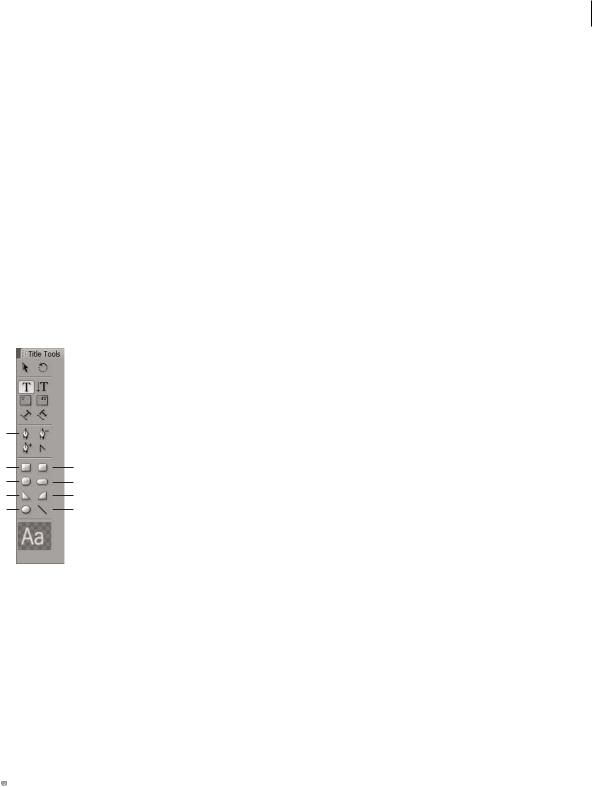
A
BF
CG
DH
EI
Titler tools panel
A. Pen Tool B. Rectangle C. Clipped Corner Rectangle D. Wedge E. Ellipse F. Rounded Corner Rectangle G. Rounded Rectangle H. Arc I. Line
Select a shape tool.
•Shift-drag to constrain the shape’s aspect ratio.
•Alt-drag (Windows) or Option-drag (Mac OS) to draw from the center of the shape.
•Shift+Alt-drag (Windows) or Shift+Option-drag (Mac OS) to constrain the aspect ratio and draw from the center.
•Drag diagonally across the corner points to flip the shape diagonally as you draw.
•Drag across, up, or down to flip the shape horizontally or vertically as you draw.
 To flip the shape after you’ve drawn it, use the Selection tool to drag a corner point in the direction you want it to flip.
Change the shape of a graphic object or a logo
1 Select one or more objects or logos in a title.
Last updated 1/16/2012

USING ADOBE PREMIERE PRO |
261 |
Titling and the Titler
2In the Title Properties panel, click the triangle next to Properties to expand its list, and then choose an option from the Graphic Type menu.
Note: When you change shapes, the original object anchor points often are lost. To reveal the object anchor points before or after changing the shape, select the object with the Selection tool.
Draw straight segments with Pen Tool
Draw straight lines by clicking Pen Tool in the drawing area. Pen Tool creates object anchor points connected by straight segments.
1Select Pen Tool.
2Position the tip of the pen point where you want the straight segment to begin, and click to define the first object anchor point. The object anchor point remains selected (solid) until you add the next point.
Note: The first segment you draw is not visible until you click a second object anchor point. Also, if lines extend from either side of the point, you’ve accidentally dragged Pen Tool; choose Edit > Undo and click again.
3Click again where you want the segment to end. (Shift-click to constrain the segment’s angle to multiples of 45°.) Pen Tool creates another object anchor point.
4Continue clicking Pen Tool to create additional straight segments. The last object anchor point you add appears as a large square, indicating that it is selected.
5Complete the path by doing one of the following:
•To close a path, click the initial object anchor point. A circle appears underneath the pen pointer when it is directly over the initial object anchor point.
•To leave the path open, Ctrl-click (Windows) or Command-click (Mac OS) anywhere away from all objects, or select a different tool in the Tools panel.
Draw curves with Pen Tool
Draw curved segments by dragging the object anchor points with Pen Tool. When you use the Selection tool to select an object anchor point connecting curved segments, the segments display direction lines, which end in direction points. The angle and length of the direction lines determine the shape and size of the curved segments. Moving the direction lines reshapes the curves. A smooth point always has two direction lines that move together as a single, straight unit. When you drag the direction point of either direction line on a smooth point, both direction lines move simultaneously. Pen Tool maintains a continuous curve at that object anchor point. In comparison, a corner point can have two, one, or no direction lines, depending on whether it joins two, one, or no curved segments, respectively.
Corner point direction lines maintain the corner by working independently of one another. When you drag a direction point on a corner point’s direction line, the other direction line, if present, does not move. Direction lines are always tangent to (perpendicular to the radius of) the curve at the object anchor points. The angle of each direction line determines the slope of the curve. The length of each direction line determines the height, or depth, of the curve.
1Select Pen Tool.
2Position the cursor where you want the curve to begin. Hold down the mouse button.
3Drag to create direction lines that determine the slope of the curve segment you’re creating. In general, extend the direction line about one third of the distance to the next object anchor point you plan to draw. Shift-drag to constrain the direction line to multiples of 45 °.
4Release the mouse button.
Note: The first segment is not visible until you create the second object anchor point.
Last updated 1/16/2012