


nRF24L01+ Product Specification
7.8Enhanced ShockBurst™ transaction diagram
This section describes several scenarios for the Enhanced ShockBurst™ automatic transaction handling. The call outs in this section’s figures indicate the IRQs and other events. For MCU activity the event may be placed at a different timeframe.
Note: The figures in this section indicate the earliest possible download (DL) of the packet to the MCU and the latest possible upload (UL) of payload to the transmitter.
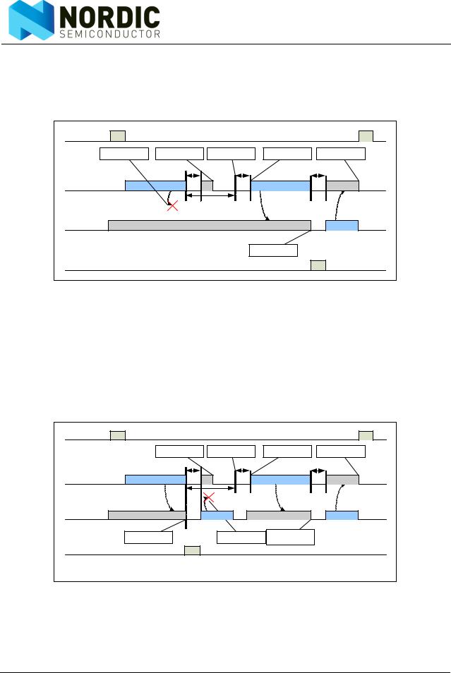
7.8.1Single transaction with ACK packet and interrupts
In Figure 18. the basic auto acknowledgement is shown. After the packet is transmitted by the PTX and received by the PRX the ACK packet is transmitted from the PRX to the PTX. The RX_DR IRQ is asserted after the packet is received by the PRX, whereas the TX_DS IRQ is asserted when the packet is acknowledged and the ACK packet is received by the PTX.
MCU PTX |
UL |
|
IRQ |
|
Ack received
IRQ:TX DS (PID=1)
PTX
PRX
|
130us1 |
TX:PID=1 |
RX |
RX |
ACK:PID=1 |
Packet received IRQ: RX DR (PID=1)
MCU PRX
DL
1 Radio Turn Around Delay
Figure 18. TX/RX cycles with ACK and the according interrupts
Revision 1.0 |
Page 45 of 78 |
nRF24L01+ Product Specification
7.8.2Single transaction with a lost packet
Figure 19. is a scenario where a retransmission is needed due to loss of the first packet transmit. After the packet is transmitted, the PTX enters RX mode to receive the ACK packet. After the first transmission, the PTX waits a specified time for the ACK packet, if it is not in the specific time slot the PTX retransmits the packet as shown in Figure 19.
MCU PTX UL |
|
|
|
IRQ |
Packet PID=1 lost |
No address detected. |
Auto retransmit delay |
Retransmit of packet |
ACK received |
during transmission |
RX off to save current |
elapsed |
PID=1 |
IRQ: TX DS (PID=1) |
|
130us1 |
130us1 |
|
130us1 |
PTX |
TX:PID=1 |
RX |
TX:PID=1 |
RX |
|
|
ARD |
|
|
PRX |
|
RX |
|
ACK:PID=1 |
|
|
|
Packet received. |
|
|
|
|
IRQ: RX DR (PID=1) |
|
MCU PRX |
|
|
|
DL |
1 Radio Turn Around Delay
Figure 19. TX/RX cycles with ACK and the according interrupts when the first packet transmit fails
When an address is detected the PTX stays in RX mode until the packet is received. When the retransmitted packet is received by the PRX (see Figure 19.), the RX_DR IRQ is asserted and an ACK is transmitted back to the PTX. When the ACK is received by the PTX, the TX_DS IRQ is asserted.
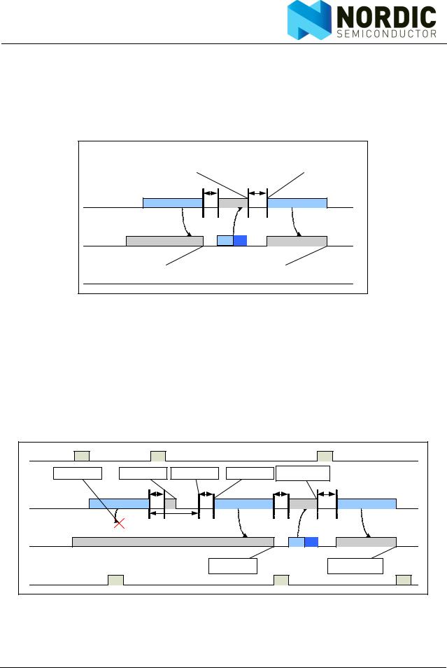
7.8.3Single transaction with a lost ACK packet
Figure 20. is a scenario where a retransmission is needed after a loss of the ACK packet. The corresponding interrupts are also indicated.
MCU PTX UL |
|
|
|
IRQ |
|
No address detected. |
Auto retransmit delay |
Retransmit of packet |
ACK received |
|
RX off to save current |
elapsed |
PID=1 |
IRQ: TX DS (PID=1) |
|
130us1 |
130us1 |
|
130us1 |
PTX |
TX:PID=1 |
RX |
TX:PID=1 |
RX |
|
|
ARD |
|
|
PRX |
RX |
ACK:PID=1 |
RX |
ACK:PID=1 |
|
Packet received. |
ACK PID=1 lost |
Packet detected as |
|
|
copy of previous, |
|
||
|
IRQ: RX DR (PID=1) |
during transmission |
|
|
|
discarded |
|
||
MCU PRX |
|
|
|
|
DL |
|
|
|
1 Radio Turn Around Delay
Figure 20. TX/RX cycles with ACK and the according interrupts when the ACK packet fails
Revision 1.0 |
Page 46 of 78 |
nRF24L01+ Product Specification
7.8.4Single transaction with ACK payload packet
Figure 21. is a scenario of the basic auto acknowledgement with payload. After the packet is transmitted by the PTX and received by the PRX the ACK packet with payload is transmitted from the PRX to the PTX. The RX_DR IRQ is asserted after the packet is received by the PRX, whereas on the PTX side the TX_DS IRQ is asserted when the ACK packet is received by the PTX. On the PRX side, the TX_DS IRQ for the ACK packet payload is asserted after a new packet from PTX is received. The position of the IRQ in Figure 21. shows where the MCU can respond to the interrupt.
MCU PTX |
UL1 |
|
|
UL2 |
|
IRQ |
|
|
|
|
|
|
|
|
|
|
|
DL |
|
|
|
|
|
|
|
|
|
|
|
|
|
|
|
|
|
|
|
|
|
|
|
|
|
|
|
|
ACK received |
|
|
|
Transmit of packet |
|
||
|
|
|
IRQ: TX DS (PID=1) |
|
|
|
|
|||
|
|
|
|
|
|
PID=2 |
|
|||
|
|
|
RX DR (ACK1PAY) |
|
|
|
|
|||
|
|
|
|
|
|
|
|
|||
PTX
PRX
130us1 |
|
≥130us3 |
TX:PID=1 |
RX |
TX:PID=2 |
RX |
ACK1 PAY |
RX |
MCU PRX
Packet received. |
|
|
|
Packet received. |
|
|
|
|
|
|
IRQ: RX DR (PID=2) |
|
|
||
IRQ: RX DR (PID=1) |
|
|
|
|
|
||
|
|
|
TX DS (ACK1PAY) |
|
|
||
|
|
|
|
|
|
|
|
|
|
|
|
|
|
|
|
UL2 |
|
|
DL |
|
|
DL |
|
|
|
|
|
|
|
|
IRQ |
1 Radio Turn Around Delay
2 Uploading Payload for Ack Packet
3 Delay defined by MCU on PTX side, ≥ 130us
Figure 21. TX/RX cycles with ACK Payload and the according interrupts
7.8.5Single transaction with ACK payload packet and lost packet
Figure 22. is a scenario where the first packet is lost and a retransmission is needed before the RX_DR IRQ on the PRX side is asserted. For the PTX both the TX_DS and RX_DR IRQ are asserted after the ACK packet is received. After the second packet (PID=2) is received on the PRX side both the RX_DR (PID=2) and TX_DS (ACK packet payload) IRQ are asserted.
MCU PTX UL1 |
UL2 |
|
|
|
DL |
|
|
|
|
IRQ |
|||
Packet PID=1 lost |
No address detected. |
Auto retransmit delay |
Retransmit of packet |
ACK received |
|
|
IRQ: TX DS (PID=1) |
||||||
during transmission |
RX off to save current |
elapsed |
PID=1 |
|||
RX DR (ACK1PAY) |
||||||
|
|
|
|
|||
|
130us1 |
130us1 |
|
130us1 |
≥130us3 |
|
PTX |
TX:PID=1 |
RX |
TX:PID=1 |
RX |
TX:PID=2 |
|
|
|
ARD |
|
|
|
|
PRX |
|
RX |
|
ACK1 PAY |
RX |
|
|
|
Packet received. |
|
Packet received. |
||
|
|
|
IRQ: RX DR (PID=2) |
|||
|
|
IRQ: RX DR (PID=1) |
|
|||
|
|
|
TX DS (ACK1PAY) |
|||
|
|
|
|
|
||
MCU PRX |
UL2 |
|
|
DL |
DL |
|
1 Radio Turn Around Delay
2 Uploading Paylod for Ack Packet
3 Delay defined by MCU on PTX side, ≥ 130us
Figure 22. TX/RX cycles and the according interrupts when the packet transmission fails
Revision 1.0 |
Page 47 of 78 |

nRF24L01+ Product Specification
7.8.6Two transactions with ACK payload packet and the first ACK packet lost
MCU PTX UL1 |
|
|
UL2 |
|
|
|
UL3 |
DL |
|
|
|
|
|
|
|
IRQ |
|
|
|||
|
|
|
No address detected. |
Auto retransmit delay |
Retransmit of packet |
ACK received |
|
ACK received |
|
|
|
|
|
IRQ: TX DS (PID=1) |
IRQ: TX DS (PID=2) |
||||||
|
|
|
RX off to save current |
elapsed |
|
PID=1 |
||||
|
|
|
|
RX DR (ACK1PAY) |
RX DR (ACK2PAY) |
|||||
|
|
|
|
|
|
|
||||
|
|
|
130us1 |
130us1 |
130us1 |
≥130us3 |
130us1 |
≥130us3 |
||
PTX |
|
|
TX:PID=1 |
RX |
|
TX:PID=1 |
RX |
TX:PID=2 |
RX |
TX:PID=3 |
|
|
|
|
ARD |
|
|
|
|
|
|
PRX |
|
|
RX |
ACK1 PAY |
|
RX |
ACK1 PAY |
RX |
ACK2 PAY |
RX |
|
Packet received. |
ACK PID=1 lost |
Packet detected as |
|
Packet received. |
|
Packet received. |
|||
|
copy of previous, |
|
IRQ: RX DR (PID=2) |
|
IRQ: RX DR (PID=3) |
|||||
|
IRQ: RX DR (PID=1) |
during transmission |
|
|
||||||
|
discarded |
|
TX DS (ACK1PAY) |
|
TX DS (ACK2PAY) |
|||||
|
|
|
|
|
|
|
|
|||
MCU PRX |
UL1 |
2 |
DL |
UL2 |
2 |
|
|
|
DL |
|
|
|
|
|
|
IRQ |
|
||||
1 Radio Turn Around Delay
2 Uploading Payload for Ack Packet
3 Delay defined by MCU on PTX side, ≥ 130us
Figure 23. TX/RX cycles with ACK Payload and the according interrupts when the ACK packet fails
In Figure 23. the ACK packet is lost and a retransmission is needed before the TX_DS IRQ is asserted, but the RX_DR IRQ is asserted immediately. The retransmission of the packet (PID=1) results in a discarded packet. For the PTX both the TX_DS and RX_DR IRQ are asserted after the second transmission of ACK, which is received. After the second packet (PID=2) is received on the PRX both the RX_DR (PID=2) and TX_DS (ACK1PAY) IRQ is asserted. The callouts explains the different events and interrupts.
7.8.7Two transactions where max retransmissions is reached
MCU PTX |
UL |
|
|
|
|
|
|
|
|
IRQ |
|
|
|
|
|
|
|
|
|
|
|
|
|
|
|
|
No address detected. |
|
Auto retransmit delay |
|
Retransmit of packet |
No address detected. |
No address detected. |
|
|
|
|
|
|
|
RX off to save current. |
|
|||||
|
|
|
RX off to save current |
|
elapsed |
|
PID=1 |
RX off to save current |
|
||
|
|
|
|
|
IRQ:MAX_RT reached |
|
|||||
|
|
|
|
|
|
|
|
|
|
||
PTX
PRX
|
130us1 |
130us1 |
130us1 |
≥130us3 |
130us1 |
|
TX:PID=1 |
RX |
TX:PID=1 |
RX |
TX:PID=1 |
RX |
|
|
ARD |
|
ARD |
|
|
|
|
|
|
|
|
130us1 |
|
|
|
|
|
|
|
|
RX |
ACK1 PAY |
|
RX |
|
ACK1 PAY |
RX |
MCU PRX
Packet received. |
|
|
|
ACK PID=1 lost |
|
ACK PID=1 lost |
|
Packet detected as |
|
ACK PID=1 lost |
||
|
|
|
|
|
copy of previous, |
|
||||||
IRQ: RX DR (PID=1) |
|
|
|
during transmission |
|
during transmission |
|
|
during transmission |
|||
|
|
|
|
|
discarded |
|
||||||
|
|
|
|
|
|
|
|
|
|
|
|
|
|
|
|
|
|
|
|
|
|
|
|
|
|
|
UL2 |
|
|
DL |
|
|
|
|
|
|
|
|
|
|
|
|
|
|
|
|
|
|
|
|
|
1 Radio Turn Around Delay
2 Uploading Paylod for Ack Packet
3 Delay defined by MCU on PTX side, ≥ 130us
Figure 24. TX/RX cycles with ACK Payload and the according interrupts when the transmission fails. ARC is set to 2.
MAX_RT IRQ is asserted if the auto retransmit counter (ARC_CNT) exceeds the programmed maximum limit (ARC). In Figure 24. the packet transmission ends with a MAX_RT IRQ. The payload in TX FIFO is NOT removed and the MCU decides the next step in the protocol. A toggle of the CE starts a new transmitting sequence of the same packet. The payload can be removed from the TX FIFO using the FLUSH_TX command.
Revision 1.0 |
Page 48 of 78 |